Sign In
Upload
Manuals
Brands
Tektronix Manuals
Portable Generator
TG700
Tektronix TG700 Manuals
Manuals and User Guides for Tektronix TG700. We have
10
Tektronix TG700 manuals available for free PDF download: Service Manual, User Manual, Technical Reference, Programming Manual, Instructions Manual, Installation Instructions Manual
Tektronix TG700 Service Manual (810 pages)
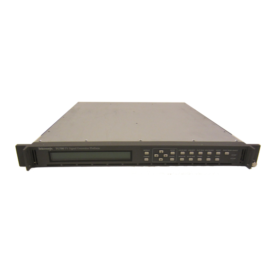
TV Signal Generator Platform
Brand:
Tektronix
| Category:
Test Equipment
| Size: 5 MB
Table of Contents
Table of Contents
9
General Safety Summary
11
Personal Injury
11
Service Safety Summary
13
Manual Structure
15
Contacting Tektronix
17
Performance Check Interval
19
Strategy for Servicing
19
Tektronix Service Offerings
20
Specifications
21
Product Overview
23
Electrical Characteristics
25
Table 1-3: Mechanical Characteristics
26
Figure 1-1: TG700 Dimensions
27
Table 1-4: Certifications and Compliances
28
Operating Information
31
Installation
33
Supplying Operating Power
33
Table 2-1: Power-Cord Conductor Identification
34
Table 2-2: Power Cord Identification
35
Operating Environment
36
Ventilation Requirements
36
Applying and Interrupting Power
36
Repackaging Instructions
37
Installed Options
38
Figure 2-1: Mainframe Main Menu
39
Figure 2-2: PRESET Submenu
40
Figure 2-3: SEQUENCE Submenu
40
Figure 2-4: FRAME RESET STATUS Submenu
41
Figure 2-5: UTILITY Submenu
42
Figure 2-6: SIGNAL KEY ASSIGN Submenu
43
Figure 2-7: NETWORK INFORMATION Submenu
43
Figure 2-8: NETWORK SETUP Submenu
44
Figure 2-9: DIAGNOSTICS Submenu
45
Module Installation
47
Preventing Component Damage
47
Installing a Module
48
Table 2-3: Module Slot Assignments
48
Figure 2-10: TG700 Slot Numbering
48
Figure 2-11: Removing the Blank Panel
49
Figure 2-12: Installing the Module
49
Removing a Module
50
Figure 2-13: Securing the Module
50
Figure 2-14: Removing the Module
51
Theory of Operation
53
A10 Main Board
55
Power Supply Module
56
Performance Verification
57
Table 4-1: Equipment Required for Performance Verification
59
Table 4-2: TG700 Calibration Data Report
60
Performance Verification Procedures
61
Figure 4-1: Equipment Connection for Verifying Subcarrier Frequency
61
Adjustment Procedures
63
Requirement for Adjustment
65
Table 5-1: Equipment Required
65
Master Clock Frequency Adjustment
66
Figure 5-1: Equipment Connection for Adjusting Master Clock Frequency
66
Maintenance
69
Related Maintenance Procedures
71
Table 6-1: Relative Susceptibility to Static-Discharge Damage
73
Inspection and Cleaning
74
Table 6-2: External Inspection Check List
74
Table 6-3: Internal Inspection Check List
76
Removal and Installation Procedures
79
General Instructions
80
Table 6-4: Summary of Procedures
80
Table 6-5: Tools Required for Module Removal
80
Figure 6-1: TG700 Orientation
81
Figure 6-2: External Modules
82
Figure 6-3: Internal Modules
83
Access Procedure
84
Figure 6-4: Guide to Removal Procedures
84
Procedures for External Modules
85
Figure 6-5: Top Cover Removal
86
Figure 6-6: Front-Panel Unit Removal
88
Figure 6-7: Disassembly of Front-Panel Assembly
89
Figure 6-8: A10 Main Board Removal
91
Figure 6-9: A40 LAN Board, Fan, and RFI Filter Removal
93
Troubleshooting
95
Troubleshooting Trees
96
Figure 6-10: Troubleshooting Procedure (1)
96
Figure 6-11: Troubleshooting Procedure (2)
97
Electrical Parts List
103
Figure 9-1: TG700 Block Diagram
110
Figure 9-2: TG700 Interconnect Diagram
111
Mechanical Parts List
113
Parts Ordering Information
115
Using the Replaceable Parts List
116
Figure 10-1: Main Chassis
119
Figure 10-2: Main Frame
121
Manual Structure
137
Related Manuals
138
Contacting Tektronix
138
Specifications
139
Product Description
141
Electrical Characteristics
142
Environmental Characteristics
143
Operating Information
145
Operating Procedure
147
AG7 Module Main Menu
148
Theory of Operation
151
Performance Verification
155
Equipment Required
157
Calibration Data Report
158
Performance Verification Procedures
159
Adjustment Procedures
163
Maintenance
167
H Troubleshooting
169
Inspection and Cleaning
171
Repackaging Instructions
171
Removal and Replacement
173
Tools Required
173
Troubleshooting
175
Equipment Required
175
Troubleshooting Trees
176
Replaceable Electrical Parts
183
Mechanical Parts List
191
Parts Ordering Information
193
Using the Replaceable Parts List
194
Table 1-2: Environmental Characteristics
203
Manual Structure
205
Related Manuals
206
Contacting Tektronix
206
Specifications
207
Product Description
209
Electrical Characteristics
210
Environmental Characteristics
212
Operating Information
213
Operating Procedure
215
Theory of Operation
219
Analog Genlock
221
Performance Verification
223
Equipment Required
225
Calibration Data Report
226
Performance Verification Procedures
227
Adjustment Procedures
239
Requirements for Adjustment
241
Equipment Required
241
Maintenance
249
H Troubleshooting
251
Inspection and Cleaning
253
Repackaging Instructions
253
Removal and Replacement
255
Tools Required
255
Troubleshooting
257
Equipment Required
257
Troubleshooting Trees
258
Replaceable Electrical Parts
265
Mechanical Parts List
273
Parts Ordering Information
275
Using the Replaceable Parts List
276
Manual Structure
287
Related Manuals
288
Contacting Tektronix
288
Specifications
289
Product Description
291
Electrical Characteristics
292
Environmental Characteristics
295
Operating Information
297
Operating Procedure
299
ATG7 Module Main Menu
302
Theory of Operation
307
Performance Verification
311
Equipment Required
313
Calibration Data Report
314
Performance Verification Procedures
316
Adjustment Procedures
329
Requirements for Adjustment
331
Equipment Required
331
Maintenance
335
H Troubleshooting
337
Inspection and Cleaning
339
Repackaging Instructions
339
Removal and Replacement
341
Tools Required
341
Troubleshooting
343
Troubleshooting Trees
344
Replaceable Electrical Parts
351
Mechanical Parts List
359
Parts Ordering Information
361
Module Servicing
361
Using the Replaceable Parts List
362
Manual Structure
373
Related Manuals
374
Contacting Tektronix
374
Specifications
375
Product Description
377
Electrical Characteristics
378
Advertisement
Tektronix TG700 Service Manual (337 pages)
TV Signal Generator Platform
Brand:
Tektronix
| Category:
Portable Generator
| Size: 4 MB
Table of Contents
Table of Contents
7
Figure 1-10: Troubleshooting Procedure
15
Figure 1-11: Troubleshooting Procedure
15
Figure 2-2: Troubleshooting Procedure
15
Figure 2-3: Troubleshooting Procedure
15
Figure 3-3: Equipment Connection for Adjusting the Output Offset and Gain
15
Figure 3-6: Troubleshooting Procedure
15
Figure 3-7: Troubleshooting Procedure
15
Figure 4-2: Troubleshooting Procedure
15
Figure 4-3: Troubleshooting Procedure
15
General Safety Summary
19
Service Safety Summary
21
Preface
23
Manual Structure
23
Manual Conventions
24
Finding Other Information
25
Introduction
26
Performance Check Interval
26
Strategy for Servicing
26
Tektronix Service Offerings
27
Maintenance for Generators and Modules
28
Preparation
28
Inspection and Cleaning
30
Repackaging Instructions
31
TG700 Platform
33
TG700 Mainframe Theory of Operation
35
A10 Main Board
35
Power Supply Module
36
TG700 Adjustment Procedures
37
Requirement for Adjustment
37
Equipment Required
37
Table 1-1: Equipment Required for TG700 Adjustment Procedures
37
Master Clock Frequency Adjustment
38
Figure 1-1: Equipment Connection for Adjusting Master Clock Frequency
38
TG700 Mainframe Maintenance
39
Related Maintenance Procedures
39
Preparation
40
Inspection and Cleaning
40
Table 1-2: External Inspection Checklist
41
Table 1-3: Internal Inspection Checklist
42
TG700 Mainframe Removal and Installation Procedures
44
Preparation
44
Table 1-4: Summary of Procedures
45
Table 1-5: Tools Required for Module Removal
45
Figure 1-2: TG700 Orientation
46
Figure 1-3: External Modules
47
Figure 1-4: Internal Modules
48
Access Procedure
49
Procedures for External Modules
49
Figure 1-5: Top Cover Removal
50
Figure 1-6: Front-Panel Unit Removal
52
Figure 1-7: Disassembly of Front-Panel Assembly
53
Procedure for Internal Modules
54
Figure 1-8: A10 Main Board Removal
55
Figure 1-9: A40 LAN Board, Fan, and RFI Filter Removal
57
TG700 Mainframe Troubleshooting
58
Diagnostics
58
Troubleshooting Trees
59
Figure 1-12: A10 Main Board (View from Top)
61
TG700 Mainframe Diagrams
62
Figure 1-13: TG700 Block Diagram
63
Figure 1-14: TG700 Interconnect Diagram
64
TG700 Mainframe Replaceable Parts List
65
Parts Ordering Information
65
Using the Replaceable Parts List
66
Table 1-6: Parts List Column Descriptions
66
Figure 1-15: Main Chassis
67
Table 1-7: Main Chassis - Replaceable Parts
67
Table 1-8: Main Frame - Replaceable Parts
68
Figure 1-16: Main Frame
69
Table 1-9: Front-Panel Unit - Replaceable Parts
70
Figure 1-17: Front-Panel Unit
71
Table 1-10: Power Supply Module - Replaceable Parts
72
Figure 1-18: Power Supply Module
73
Figure 1-19: Blank Panel
74
Table 1-11: Blank Panel - Replaceable Parts
74
Table 1-12: Standard and Optional Accessories for TG700 Mainframe
74
Removing a Module
75
AG7 Audio Generator
77
AG7 Audio Generator Theory of Operation
79
Figure 2-1: Simplified Block Diagram of the AG7 Generator Module
79
AG7 Audio Generator Maintenance
80
AG7 Audio Generator Removal and Replacement
81
Tools Required
81
Replacing the Rear-Panel Connectors and Chassis
81
Table 2-1: Required Tools for Removal and Replacement of AG7 Audio Generator
81
AG7 Audio Generator Troubleshooting
83
Equipment Required
83
Backing up the Instrument Settings
83
Table 2-2: Equipment Required for AG7 Audio Generator Troubleshooting
83
Troubleshooting Trees
84
AG7 Audio Generator Diagram
86
Figure 2-4: AG7 Generator Module Connections
86
AG7 Audio Generator Replaceable Parts List
87
Table 2-3: AG7 Generator Module - Replaceable Parts
87
Figure 2-5: AG7 Generator Module Exploded View
88
AGL7 Analog Genlock Module
89
AGL7 Analog Genlock Module Theory of Operation
91
Analog Genlock
91
Black Burst Generator
91
Figure 3-1: Simplified Block Diagram of the AGL7 Genlock Module
92
AGL7 Analog Genlock Adjustment Procedures
93
Requirements for Adjustment
93
Equipment Required
93
Table 3-1: Equipment Required for AGL7 Adjustment Procedures
93
Output Offset and Gain Adjustment
94
Figure 3-2: AGL7 Circuit Board View
94
Clock Timing Adjustment (Board Number 671-B089-XX and 671-B279-00 Only)
97
Figure 3-4: Timing Relationship between CH1 and CH2 Signals
99
AGL7 Analog Genlock Module Maintenance
101
AGL7 Analog Genlock Module Removal and Replacement
102
Tools Required
102
Replacing the Rear-Panel Connectors and Chassis
102
Table 3-2: Required Tools for Removal and Replacement of AGL7 Analog Genlock Module
102
Figure 3-5: Dressing the AGL7 BNC Cables
103
AGL7 Analog Genlock Module Troubleshooting
104
Equipment Required
104
Backing up the Instrument Settings
104
Table 3-3: Equipment Required for AGL7 Analog Genlock Module Troubleshooting
104
Troubleshooting Trees
105
AGL7 Analog Genlock Module Diagram
107
Figure 3-8: AGL7 Genlock Module Connections
107
AGL7 Analog Generator Module Replaceable Parts List
108
Table 3-4: AGL7 Analog Generator Module - Replaceable Parts
108
Figure 3-9: AGL7 Genlock Module Exploded View
109
ATG7 Analog Test Generator
111
ATG7 Analog Test Generator Theory of Operation
113
Figure 4-1: Simplified Block Diagram of the ATG7 Generator Module
113
ATG7 Analog Test Generator Maintenance
114
ATG7 Analog Test Generator Removal and Replacement
115
Tools Required
115
Replacing the Rear-Panel Connectors and Chassis
115
Table 4-1: Required Tools for Removal and Replacement of ATG7 Test Generator
115
ATG7 Analog Test Generator Troubleshooting
117
Equipment Required
117
Backing up the Instrument Settings
117
Table 4-2: Equipment Required for ATG7 Test Generator Troubleshooting
117
Troubleshooting Trees
118
ATG7 Analog Test Generator Diagram
120
Figure 4-4: ATG7 Generator Module Connections
120
ATG7 Analog Test Generator Replaceable Parts List
121
Table 4-3: ATG Analog Test Generator - Replaceable Parts
121
Figure 4-5: ATG7 Generator Module Exploded View
122
AVG7 Analog Video Generator
123
AVG7 Analog Video Generator Theory of Operation
125
Figure 5-1: Simplified Block Diagram of the AVG7 Generator Module
126
AVG7 Analog Video Generator Adjustment Procedures
127
Requirements for Adjustment
127
Equipment Required
128
Output Offset and Gain Adjustment
128
Table 5-1: Equipment Required AVG7 Analog Video Generator Adjustment Procedures
128
Figure 5-2: Location of the Variable Resistors for the Output Offset and Gain Adjustment
129
Frame Timing and Clock Timing Adjustments
131
Figure 5-4: Location of the Test Points for the Frame Timing and Clock Timing Adjustment
132
Group Delay Adjustment
134
Figure 5-6: Equipment Connection for Adjusting the Group Delay
135
Figure 5-7: Adjusting the Baseline of the Modulated 20T Pulse Signal
136
Frequency Response Adjustment
137
Figure 5-9: Equipment Connection for Adjusting the Frequency Response
138
Figure 5-10: Adjusting the Signal Amplitudes
140
Interchannel Delay Adjustment
141
Figure 5-12: Equipment Connection for Adjusting the Interchannel Delay
142
Frequency Response Confirmation
144
Interchannel Delay Confirmation
144
AVG7 Analog Video Generator Maintenance
145
AVG7 Analog Video Generator Removal and Replacement
146
Tools Required
146
Replacing the Rear-Panel Connectors and Chassis
146
Table 5-2: Required Tools for Removal and Replacement of AVG7 Analog Video Generator
146
AVG7 Analog Video Generator Troubleshooting
148
Equipment Required
148
Backing up the Instrument Settings
148
Table 5-3: Equipment Required for AVG7 Analog Video Generator Troubleshooting
148
Troubleshooting Trees
149
Figure 5-14: Troubleshooting Procedure (2)
150
AVG7 Analog Video Generator Diagram
151
AVG7 Analog Video Generator Replaceable Parts List
152
Table 5-4: AVG7 Analog Video Generator - Replaceable Parts
152
Figure 5-16: AVG7 Generator Module Exploded View
153
AWVG7 Analog Wideband Video Generator
155
AWVG7 Analog Wideband Video Generator Theory of Operation
157
Figure 6-1: Simplified Block Diagram of the AWVG7 Generator Module
158
AWVG7 Analog Wideband Video Generator Adjustment Procedures
159
Requirements for Adjustment
159
Equipment Required
160
Output Offset and Gain Adjustment
160
Table 6-1: Equipment Required for AWVG7 Analog Wideband Video Generator Adjustment Procedures
160
Figure 6-2: Location of the Variable Resistors for the Output Offset and Gain Adjustment
161
Frame Timing and Clock Timing Adjustments
163
Figure 6-4: Location of the Test Points for the Frame Timing and Clock Timing Adjustment
164
Frequency Response Adjustment
166
Figure 6-6: Equipment Connection for Adjusting the Frequency Response
167
Figure 6-7: Minimizing the Amplitude Changes
169
AWVG7 Analog Wideband Video Generator Maintenance
170
AWVG7 Analog Wideband Video Generator Removal and Replacement
171
Tools Required
171
Replacing the Rear-Panel Connectors and Chassis
171
Table 6-2: Required Tools for Removal and Replacement of AWVG7 Analog Wideband Video
171
AWVG7 Analog Wideband Video Generator Troubleshooting
173
Equipment Required
173
Backing up the Instrument Settings
173
Table 6-3: Equipment Required for AWVG7 Analog Wideband Video Generator Troubleshooting
173
Troubleshooting Trees
174
Figure 6-9: Troubleshooting Procedure (2)
175
AWVG7 Analog Wideband Video Generator Diagram
176
AWVG7 Analog Wideband Video Generator Replaceable Parts List
177
Table 6-4: AWVG7 Analog Wideband Video Generator - Replaceable Parts
177
Figure 6-11: AWVG7 Generator Module Exploded View
178
Tektronix TG700 User Manual (355 pages)
TV Signal Generator Platform
Brand:
Tektronix
| Category:
Inverter
| Size: 7 MB
Table of Contents
Table of Contents
9
List of Tables
16
General Safety Summary
18
Service Safety Summary
20
Compliance Information
21
EMC Compliance
21
Safety Compliance
22
Environmental Considerations
24
Preface
25
Products
25
About this Manual
25
Related Manuals
26
Getting Started
27
Product Description
29
Mainframe Memory Requirements
30
Accessories
31
Options
31
Table 1-1: Standard and Optional Accessories
31
Table 1-2: Instrument and Module Options
31
Initial Product Inspection
33
Mainframe Installation
33
Figure 1-1: Installing the Rackmount Hardware
34
Figure 1-2: Placing the TG700 in the Rack
35
Table 1-3: TG700 Environmental Requirements
35
Table 1-4: AC Line Power Requirements
36
Module Installation and Removal
37
Figure 1-3: TG700 Slot Numbering
38
Figure 1-4: Removing the Blank Panel
39
Figure 1-5: Installing the Module
39
Figure 1-6: Securing the Module
40
Functional Checks
41
Figure 1-7: Removing the Module
41
Operating Basics
67
Front-Panel Controls
69
Figure 2-1: TG700 Front Panel
69
Rear-Panel Connectors
71
Figure 2-2: TG700 Rear Panel
71
Figure 2-3: AG7 Module Connectors
72
Figure 2-4: Location of J452 on the AG7 Module
72
Figure 2-5: AGL7 Module Connectors
73
Figure 2-6: Location of J040 and J960 on the AGL7 Module
74
Figure 2-7: ATG7 Module Connectors
75
Figure 2-8: AVG7 Module Connectors
75
Figure 2-9: AWVG7 Module Connectors
76
Figure 2-10: BG7 Module Connectors
76
Figure 2-11: DVG7 Module Connectors (Option BK)
77
Figure 2-12: GPS7 Module Connectors
78
Table 2-1: GPS7 Module LTC/GPI Connector Pin Assignments
79
Figure 2-13: HD3G7 Module Connectors
80
Figure 2-14: HDLG7 Module Connectors
81
Figure 2-15: HDVG7 Module Connectors (Option BK)
82
Frame Reset Signals
83
Clock Conflict Messages
84
Fan Failure Warning Message
85
Using the Mainframe Menus
86
Figure 2-16: Mainframe Main Menu
86
Figure 2-17: PRESET Submenu
87
Figure 2-18: SEQUENCE Submenu
89
Figure 2-19: FRAME RESET STATUS Submenu
90
Figure 2-20: UTILITY Submenu
91
Figure 2-21: SIGNAL KEY ASSIGN Submenu
93
Figure 2-22: NETWORK INFORMATION Submenu
94
Figure 2-23: NETWORK SETUP Submenu
95
Figure 2-24: DIAGNOSTICS Submenu
97
Figure 2-25: Internal Frequency Calibration Menu
98
Figure 2-26: Gain Calibration Menu
98
Connecting to a Network
99
Figure 2-27: Pin Connections for a 10BASE-T Crossover Ethernet Cable
99
Using the Mainframe General Purpose Interface (GPI)
101
Figure 2-28: Top Cover Removal
102
Figure 2-29: Location of the Mainframe GPI Connectors on the A10 MAIN Board
102
Figure 2-30: Applying the Mainframe GPI Label to the Rear Panel
103
Table 2-2: Mainframe GPI Jumper Settings on the A10 MAIN Board
103
Table 2-3: Pin Assignments of the 10 BASE-T Connector for the Mainframe GPI
104
Table 2-4: Signal Level Combinations and the Corresponding Preset for the Mainframe GPI
104
Figure 2-31: Mainframe GPI ALARM Menu
106
Inspection and Cleaning
111
Table 2-5: External Inspection Check List
111
AG7 Audio Generator Module
115
Product Description
115
Operating Procedure
116
AG7 Module Main Menu
117
Figure 3-2: AG7 Module CHANNEL PARAMETERS Submenu
118
Figure 3-3: AG7 Module AUDIO TIMING Submenu
119
Factory Default Settings
120
Table 3-1: AG7 Module Factory Default Settings
120
AGL7 Analog Genlock Module
121
Product Description
121
Operating Procedure
122
AGL7 Module Main Menu
123
Figure 3-5: AGL7 Module GENLOCK Submenu
124
Figure 3-6: AGL7 Module OUTPUT Submenu
126
Figure 3-7: AGL7 Module SIGNAL Submenu
127
Figure 3-8: AGL7 Module TIMING Submenu
128
Table 3-2: Timing Adjustment Ranges for AGL7 Input Signals
129
Table 3-3: Timing Adjustment Ranges for AGL7 Output Signals
129
Factory Default Settings
130
Table 3-4: AGL7 Module Factory Default Settings
130
ATG7 Analog Test Generator
131
Product Description
131
Operating Procedure
132
Selecting an Output Signal
133
Table 3-5: ATG7 Signal Sets Assigned to the Test Signal Buttons
134
ATG7 Module Main Menu
135
Figure 3-11: ATG7 Module SELECT OUTPUT Submenu
136
Table 3-6: Test Signals in the ATG7 SELECT SIGNAL Submenu
137
Figure 3-12: ATG7 Module SELECT SIGNAL Submenu
137
Figure 3-13: ATG7 Module ID TEXT Submenu
138
Figure 3-14: ATG7 Module TIMING Submenu
140
Figure 3-15: ATG7 Module APL Submenu
141
Factory Default Settings
142
Table 3-7: ATG7 Module Factory Default Settings
142
AVG7 Analog Video Generator
143
Product Description
143
Operating Procedure
144
Selecting an Output Signal
145
Table 3-8: AVG7 Signal Sets Assigned to the Test Signal Buttons
146
Figure 3-16: Front-Panel Test Signal Buttons
146
AVG7 Module Main Menu
150
Figure 3-18: AVG7 Module MOVING PICTURE Submenu
152
Figure 3-19: AVG7 Module OVERLAY Submenu
153
Figure 3-20: AVG7 Module LOGO Submenu
154
Figure 3-21: AVG7 Module ID TEXT Submenu
155
Figure 3-22: AVG7 Module CIRCLE Submenu
157
Figure 3-23: AVG7 Module TIMING Submenu
158
Figure 3-24: AVG7 Module VIDEO Submenu
159
Figure 3-25: AVG7 Module APL Submenu
161
Factory Default Settings
162
Table 3-9: AVG7 Module Factory Default Settings
162
AWVG7 Analog Wideband Video Generator
163
Product Description
163
Operating Procedure
164
Selecting an Output Signal
165
Table 3-10: AWVG7 Signal Set Assigned to the Test Signal Buttons
166
Figure 3-26: Front-Panel Test Signal Buttons
166
AWVG7 Module Main Menu
167
Figure 3-28: AWVG7 Module MOVING PICTURE Submenu
168
Figure 3-29: AWVG7 Module OVERLAY Submenu
169
Figure 3-30: AWVG7 Module LOGO Submenu
170
Figure 3-31: AWVG7 Module ID TEXT Submenu
171
Figure 3-32: AWVG7 Module CIRCLE Submenu
173
Figure 3-33: AWVG7 Module TIMING Submenu
174
Table 3-11: Timing Adjustment Ranges for AWVG7 Module Output Signals
175
Figure 3-34: AWVG7 Module VIDEO Submenu
176
Factory Default Settings
177
Table 3-12: AWVG7 Module Factory Default Settings
177
BG7 Black Generator
178
Product Description
178
Operating Procedure
179
BG7 Module Main Menu
180
Figure 3-36: BG7 Module SELECT FORMAT Submenu
181
Table 3-13: BG7 Module Signals for each Signal Format
182
Figure 3-37: BG7 Module SELECT SIGNAL Submenu
182
Figure 3-38: BG7 Module TIMING Submenu
183
Figure 3-39: BG7 Module TIMECODE Submenu
184
Figure 3-40: BG7 Module VITC Submenu
186
Factory Default Settings
187
Table 3-14: BG7 Module Factory Default Settings
187
DVG7 Digital Video Generator
188
Product Description
188
Operating Procedure
189
Selecting an Output Signal
190
Table 3-15: DVG7 Module Signal Set Assigned to the Test Signal Buttons
191
Figure 3-41: Front-Panel Test Signal Buttons
191
DVG7 Module Main Menu
193
Figure 3-42: DVG7 Module Main Menu
194
Figure 3-43: DVG7 Module MOVING PICTURE Submenu
196
Figure 3-44: DVG7 Module OVERLAY Submenu
197
Figure 3-45: DVG7 Module LOGO Submenu
198
Figure 3-46: DVG7 Module ID TEXT Submenu
199
Figure 3-47: DVG7 Module CIRCLE Submenu
201
Figure 3-48: DVG7 Module AUDIO GROUP Submenu
202
Figure 3-49: DVG7 Module AUDIO CHANNEL Submenu
203
Figure 3-50: DVG7 Module TIMING Submenu
205
Figure 3-51: DVG7 Module VIDEO Submenu
206
Figure 3-52: DVG7 Module BLACK Submenu (Option BK Only)
208
Factory Default Settings
209
Table 3-16: DVG7 Module Factory Default Settings
209
GPS7 GPS Synchronization and Timecode Module
211
Product Description
212
Operating Procedure
213
Configure the GPS7 Module
214
Table 3-17: Figures of Merit for Signal Quality
219
GPS7 Module Main Menu
226
Figure 3-55: GPS7 Module Main Menu
227
Figure 3-56: GPS7 Module REFERENCE Submenu
230
Figure 3-57: GPS7 Module BLACK Submenu
233
Table 3-18: GPS7 Module Output Signal Formats
234
Figure 3-58: GPS7 Module TIMING Submenu
234
Figure 3-59: GPS7 Module TIMECODE Submenu
236
Figure 3-60: GPS7 Module VITC Submenu
237
Figure 3-61: GPS7 Module GPS SETUP Submenu
238
Figure 3-62: GPS7 Module TIME of DAY Submenu
240
Figure 3-63: GPS7 Module TIME ZONE OFFSET Submenu
242
Figure 3-64: GPS7 Module DST SCHEDULE Submenu
243
Figure 3-65: GPS7 Module PROGRAM TIME Submenu
244
Figure 3-66: GPS7 Module JAM SYNC Submenu
245
Figure 3-67: GPS7 Module LEAP SECOND Submenu
246
Figure 3-68: GPS7 Module ALARM TIME Submenu
247
Figure 3-69: GPS7 Module ALARM DELAY Submenu
248
Figure 3-70: GPS7 Module LTC Submenu
249
Table 3-19: LTC Output Signal Formats
250
Figure 3-71: GPS7 Module LTC TIMING Submenu
251
Figure 3-73: GPS7 Module GPO Submenu
252
Figure 3-74: GPS7 Module DIAGNOSTICS Submenu
253
Factory Default Settings
255
Table 3-20: GPS7 Module Factory Default Settings
255
HD3G7 HD 3 Gb/S SDI Video Generator
257
Product Description
258
Operating Procedure
259
Selecting an Output Signal
260
Table 3-21: HD3G7 Generator Mode - 3G Level a (1920 × 1080)
260
Table 3-22: HD3G7 Generator Mode - 3G Level a (1280 × 720)
260
Table 3-23: HD3G7 Generator Mode - 3G Level a (2K × 1080)
260
Table 3-24: HD3G7 Generator Mode - 3G Level B (1920 × 1080)
261
Table 3-25: HD3G7 Generator Mode - 3G Level B (2K × 1080)
261
Table 3-26: HD3G7 Generator Mode - 3G Level B (2×HD 1080)
261
Table 3-27: HD3G7 Generator Mode - 3G Level B (2Xhd 720)
261
Table 3-28: HD3G7 Generator Mode - HD-SDI (1920 × 1080)
261
Table 3-29: HD3G7 Generator Mode - HD-SDI (1280 × 720)
261
Figure 3-75: Front-Panel Test Signal Buttons
265
Zone Plate Signals
271
Zone Plate Pattern Control Parameters
274
Table 3-34: Zone Plate Pattern Control Parameters
275
Zone Plate Dependent Parameters
276
Using Zone Plate Signals
283
HD3G7 Module Main Menu
284
Figure 3-81: HD3G7 Module Main Menu
285
Figure 3-82: HD3G7 Module Main Menu (Continued)
286
Figure 3-83: HD3G7 Module STATUS Menu in Generator Mode
289
Figure 3-84: HD3G7 Module OUTPUT MODE Submenu
290
Figure 3-85: HD3G7 Module MOVING PICTURE Submenu
291
Figure 3-86: HD3G7 Module AUDIO (EMBEDDED) Submenu
292
Figure 3-87: HD3G7 Module AUDIO : CHANNEL Submenu
293
Figure 3-88: HD3G7 Module TIMING Submenu
295
Figure 3-89: HD3G7 Module TIMECODE Submenu
296
Figure 3-90: HD3G7 Module VIDEO Submenu
298
Figure 3-91: Ancillary Payload Submenu
301
Figure 3-92: Ancillary Payload Submenu (Continued)
302
Figure 3-93: AFD Code '1001' for a 16:9 Coded Frame
306
Figure 3-94: HD3G7 Module TRIGGER OUTPUT Submenu
307
Figure 3-95: HD3G7 Module DIAGNOSTICS Submenu
308
Factory Default Settings
311
HDLG7 HD Dual Link Video Generator
313
Product Description
313
Operating Procedure
314
Selecting an Output Signal
315
Table 3-36: HDLG7 Module Signal Formats
316
Figure 3-96: Front-Panel Test Signal Buttons
317
Table 3-37: HDLG7 Module HD Test Signal Set Assigned to the Test Signal Buttons
318
Table 3-38: HDLG7 Module Projector Test Pattern Set Assigned to the Test Signal Buttons
319
HDLG7 Module Main Menu
322
Table 3-39: HDLG7 Module Sample Structure/Depth Signal Formats
323
Figure 3-98: HDLG7 Module LINK OFFSET Submenu
325
Factory Default Settings
326
HDVG7 HDTV Digital Video Generator
327
Product Description
327
Operating Procedure
328
Selecting an Output Signal
329
Figure 3-100: Front-Panel Test Signal Buttons
330
HDVG7 Module Main Menu
331
Figure 3-101: HDVG7 Module Main Menu
332
Figure 3-102: HDVG7 Module MOVING PICTURE Submenu
334
Figure 3-103: HDVG7 Module OVERLAY Submenu
335
Figure 3-104: HDVG7 Module LOGO Submenu
336
Figure 3-105: HDVG7 Module ID TEXT Submenu
337
Figure 3-106: HDVG7 Module CIRCLE Submenu
339
Figure 3-107: HDVG7 Module AUDIO GROUP Submenu
340
Figure 3-108: HDVG7 Module AUDIO CHANNEL Submenu
341
Figure 3-109: HDVG7 Module TIMING Submenu
343
Figure 3-110: HDVG7 Module TIMECODE Submenu
344
Figure 3-111: HDVG7 Module VIDEO Submenu
345
Figure 3-112: HDVG7 Module BLACK Submenu (Option BK Only)
346
Factory Default Settings
347
Index
349
Advertisement
Tektronix TG700 User Manual (343 pages)
TV Signal Generator Platform
Brand:
Tektronix
| Category:
Portable Generator
| Size: 7 MB
Table of Contents
Table of Contents
9
List of Tables
16
General Safety Summary
18
Service Safety Summary
20
Compliance Information
21
EMC Compliance
21
Safety Compliance
22
Environmental Considerations
24
About this Manual
25
Preface
25
Products
25
Related Manuals
26
Getting Started
27
Product Description
29
Mainframe Memory Requirements
30
Accessories
31
Options
31
Table 1-1: Standard and Optional Accessories
31
Table 1-2: Instrument and Module Options
31
Initial Product Inspection
33
Mainframe Installation
33
Figure 1-1: Installing the Rackmount Hardware
34
Figure 1-2: Placing the TG700 in the Rack
35
Table 1-3: TG700 Environmental Requirements
35
Table 1-4: AC Line Power Requirements
36
Module Installation and Removal
37
Figure 1-3: TG700 Slot Numbering
38
Figure 1-4: Removing the Blank Panel
39
Figure 1-5: Installing the Module
39
Figure 1-6: Securing the Module
40
Figure 1-7: Removing the Module
41
Functional Checks
41
Operating Basics
67
Figure 2-1: TG700 Front Panel
69
Front-Panel Controls
69
Figure 2-2: TG700 Rear Panel
71
Rear-Panel Connectors
71
Figure 2-3: AG7 Module Connectors
72
Figure 2-4: Location of J452 on the AG7 Module
73
Figure 2-5: AGL7 Module Connectors
73
Figure 2-6: Location of J040 and J960 on the AGL7 Module
75
Figure 2-7: ATG7 Module Connectors
75
Figure 2-8: AVG7 Module Connectors
76
Figure 2-9: AWVG7 Module Connectors
76
Figure 2-10: BG7 Module Connectors
77
Figure 2-11: DVG7 Module Connectors (Option BK)
77
Figure 2-12: GPS7 Module Connectors
78
Table 2-1: GPS7 Module LTC/GPI Connector Pin Assignments
79
Figure 2-13: HD3G7 Module Connectors
80
Figure 2-14: HDLG7 Module Connectors
81
Figure 2-15: HDVG7 Module Connectors (Option BK)
81
Frame Reset Signals
82
Clock Conflict Messages
83
Fan Failure Warning Message
84
Figure 2-16: Mainframe Main Menu
85
Using the Mainframe Menus
85
Figure 2-17: PRESET Submenu
87
Figure 2-18: SEQUENCE Submenu
88
Figure 2-19: FRAME RESET STATUS Submenu
89
Figure 2-20: UTILITY Submenu
90
Figure 2-21: SIGNAL KEY ASSIGN Submenu
92
Figure 2-22: NETWORK INFORMATION Submenu
93
Figure 2-23: NETWORK SETUP Submenu
94
Figure 2-24: DIAGNOSTICS Submenu
96
Figure 2-25: Internal Frequency Calibration Menu
97
Figure 2-26: Gain Calibration Menu
97
Connecting to a Network
98
Figure 2-27: Pin Connections for a 10BASE-T Crossover Ethernet Cable
98
Using the Mainframe General Purpose Interface (GPI)
100
Figure 2-28: Top Cover Removal
101
Figure 2-29: Location of the Mainframe GPI Connectors on the A10 MAIN Board
101
Figure 2-30: Applying the Mainframe GPI Label to the Rear Panel
102
Table 2-2: Mainframe GPI Jumper Settings on the A10 MAIN Board
102
Table 2-3: Pin Assignments of the 10 BASE-T Connector for the Mainframe GPI
103
Table 2-4: Signal Level Combinations and the Corresponding Preset for the Mainframe GPI
103
Figure 2-31: Mainframe GPI ALARM Menu
105
Inspection and Cleaning
109
Table 2-5: External Inspection Check List
109
AG7 Audio Generator Module
113
Product Description
113
AG7 Module Main Menu
114
Operating Procedure
114
Factory Default Settings
117
Table 3-1: AG7 Module Factory Default Settings
117
AGL7 Analog Genlock Module
119
Product Description
119
Operating Procedure
120
AGL7 Module Main Menu
121
Table 3-2: Timing Adjustment Ranges for AGL7 Input Signals
127
Table 3-3: Timing Adjustment Ranges for AGL7 Output Signals
128
Factory Default Settings
129
Table 3-4: AGL7 Module Factory Default Settings
129
ATG7 Analog Test Generator
130
Product Description
130
Operating Procedure
131
Selecting an Output Signal
132
Table 3-5: ATG7 Signal Sets Assigned to the Test Signal Buttons
133
ATG7 Module Main Menu
134
Table 3-6: Test Signals in the ATG7 SELECT SIGNAL Submenu
136
Factory Default Settings
141
Table 3-7: ATG7 Module Factory Default Settings
141
AVG7 Analog Video Generator
142
Product Description
142
Operating Procedure
143
Selecting an Output Signal
144
Table 3-8: AVG7 Signal Sets Assigned to the Test Signal Buttons
145
AVG7 Module Main Menu
148
Factory Default Settings
160
Table 3-9: AVG7 Module Factory Default Settings
160
AWVG7 Analog Wideband Video Generator
161
Product Description
161
Operating Procedure
162
Selecting an Output Signal
163
Table 3-10: AWVG7 Signal Set Assigned to the Test Signal Buttons
164
AWVG7 Module Main Menu
165
Table 3-11: Timing Adjustment Ranges for AWVG7 Module Output Signals
173
Factory Default Settings
176
Table 3-12: AWVG7 Module Factory Default Settings
176
BG7 Black Generator
177
Product Description
177
BG7 Module Main Menu
178
Operating Procedure
178
Table 3-13: BG7 Module Signals for each Signal Format
180
Factory Default Settings
184
Table 3-14: BG7 Module Factory Default Settings
184
DVG7 Digital Video Generator
186
Product Description
186
Operating Procedure
187
Selecting an Output Signal
187
Table 3-15: DVG7 Module Signal Set Assigned to the Test Signal Buttons
189
DVG7 Module Main Menu
191
Factory Default Settings
206
Table 3-16: DVG7 Module Factory Default Settings
206
GPS7 GPS Synchronization and Timecode Module
208
Product Description
208
Operating Procedure
209
Configure the GPS7 Module
210
GPS7 Module Main Menu
222
Table 3-18: GPS7 Module Output Signal Formats
230
Table 3-19: LTC Output Signal Formats
246
Factory Default Settings
250
Table 3-20: GPS7 Module Factory Default Settings
250
HD3G7 HD 3 Gb/S SDI Video Generator
253
Product Description
253
Operating Procedure
254
Selecting an Output Signal
255
Table 3-21: HD3G7 Generator Mode - Level a (1920 × 1080)
255
Table 3-22: HD3G7 Generator Mode - Level B (1920 × 1080)
255
Table 3-23: HD3G7 Generator Mode - Level B (2K × 1080)
256
Table 3-24: HD3G7 Generator Mode - Level a (2K × 1080)
256
Table 3-25: HD3G7 Generator Mode - Level B (2×HD 1920 × 1080)
256
Table 3-26: HD3G7 Converter Mode - Level a 1920 × 1080 Formats
256
Table 3-27: HD3G7 Converter Mode - Level B (1920 × 1080)
257
Table 3-28: HD3G7 Converter Mode - Level B (2×HD 1920 × 1080)
257
Table 3-29: HD3G7 Module Test Signal Set Assigned to the Test Signal Buttons
260
Zone Plate Signals
261
Zone Plate Pattern Control Parameters
264
Zone Plate Dependent Parameters
266
Using Zone Plate Signals
272
HD3G7 Module Main Menu
273
Factory Default Settings
298
HDLG7 HD Dual Link Video Generator
301
Product Description
301
Operating Procedure
302
Selecting an Output Signal
303
HDLG7 Module Main Menu
309
Factory Default Settings
314
HDVG7 HDTV Digital Video Generator
315
Product Description
315
Operating Procedure
316
Selecting an Output Signal
317
HDVG7 Module Main Menu
319
Factory Default Settings
334
Index
337
Tektronix TG700 Technical Reference (224 pages)
TV Signal Generator Platform
Brand:
Tektronix
| Category:
Portable Generator
| Size: 1 MB
Table of Contents
Table of Contents
7
Table 2: Environmental Characteristics
10
Table 3: Mechanical Characteristics
10
Table 8: Environmental Characteristics
10
Table 12: Environmental Characteristics
10
Table 27: Serial Digital Video Signal Outputs
10
Table 28: Serial Digital Black Signal Outputs (Option BK Only)
10
Table 29: Embedded Audio
10
Table 30: Environmental Characteristics
11
General Safety Summary
12
Preface
15
Products
15
Related User Documents
16
Specifications
17
TG700 Mainframe Specifications
17
Table 1: Electrical Characteristics
17
Figure 1: TG700 Dimensions
19
AG7 Specifications
20
Table 4: AES/EBU Serial Digital Audio Outputs
20
Table 5: SILENCE Output
20
Table 6: 48 Khz CLOCK Output
20
Table 7: Output Timing
21
AGL7 Specifications
22
Table 9: Electrical Characteristics, Genlock Function
22
Table 10: Black Burst Signal and HDTV Trilevel Sync Signal Outputs
22
Table 11: Word Clock Signal Output
23
ATG7 Specifications
24
Table 13: Black Burst and Timing Pulse Outputs
24
Table 14: Color Bars Signal Output
25
Table 15: Test Signal Output
26
Table 16: Common Outputs Characteristics
27
Table 17: Environmental Characteristics
27
AVG7 Specifications
28
Table 18: Output Channels
28
Table 19: Common Output Characteristics
28
Table 20: Environmental Characteristics
29
AWVG7 Specifications
30
Table 21: Output Channels
30
Table 22: Common Output Characteristics
30
Table 23: Environmental Characteristics
31
BG7 Specifications
32
Table 24: Black Burst and HDTV Trilevel Sync Outputs
32
Table 25: Color Bars and Black Burst with Field ID Outputs (Option CB)
32
Table 26: Environmental Characteristics
33
DVG7 Specifications
34
GPS7 Specifications
36
Table 31: Black Burst and Sine Outputs
36
Table 32: Antenna Input
37
Table 33: Timebase
38
Table 34: LTC Outputs
40
Table 35: LTC Inputs
40
Table 36: GPI Signals
41
Table 37: Genlock Function (Valid Only for Models with REF in Connector on Rear Panel)
42
Table 38: Environmental Characteristics
43
HD3G7 Specifications
44
Table 40: Trigger / Clock Outputs
45
Table 41: HD SDI Input
46
Table 43: Signal Sets Assigned to the Test Signal Buttons
47
Table 44: Convertor Mode Embedded Audio and Ancillary Data
49
Table 46: Generator Mode – HD-SDI (1920 × 1080)
50
Table 51: Generator Mode – 3G Level B (1920 × 1080)
51
Table 55: Converter Mode – 3G Level a (1920 × 1080)
52
Table 58: Mechanical Characteristics
53
HDLG7 Specifications
54
Table 63: Synthesizer Generated HD Test Signals
55
Table 65: Embedded Audio and Ancillary Data
57
Table 66: Supported Input and Output Formats (SMPTE 274M to SMPTE 372M Standards)
58
Table 67: Mechanical Characteristics
59
HDVG7 Specifications
60
Table 71: Embedded Audio
61
SDI7 Specifications
62
Table 74: Trigger / Clock Output
64
Table 76: Signal Sets Assigned to the Test Signal Buttons
65
Table 77: Embedded Audio and Ancillary Data
67
Table 78: SD-525 (720 × 486)
68
Table 85: (Option 3G Only) – 3G Level B (1920 × 1080)
69
Table 89: Mechanical Characteristics
70
Tektronix TG700 Programming Manual (218 pages)
TV Signal Generator Platform
Brand:
Tektronix
| Category:
Inverter
| Size: 0 MB
Table of Contents
Table of Contents
5
Preface
9
Related Manuals
9
Getting Started
11
Figure 1- 1: Command Parts
13
Overview of the Manual
13
Figure 1- 2: 10 Base-T Connector (Rear Panel)
14
Connecting the Interface
14
Syntax and Commands
15
TG700 Syntax
17
Programming Model
18
Figure 2- 1: Example of SCPI Subsystem Hierarchy Tree
20
SCPI Commands and Queries
20
Table 2- 1: Parameter Types Used in Syntax Descriptions
21
Figure 2- 2: Example of Abbreviating a Command
22
Figure 2- 3: Example of Chaining Commands and Queries
23
Figure 2- 4: Example of Omitting Root and Lower-Level Nodes in a Chained Message
23
Table 2- 2: BNF Symbols and Meanings
25
IEEE 488.2 Common Commands
25
Constructed Mnemonics
26
Block Arguments
26
Special Characters
27
TG700 Remote Commands
29
Common Commands
29
DISPLAY Commands
31
INSTRUMENT Commands
32
MASS MEMORY Commands
33
PROGRAM Commands
36
SENSE Commands
37
STATUS Commands
38
SYSTEM Commands
41
AG7 Audio Generator Module Remote Commands
43
OUTPUT Commands
43
SENSE Commands
45
AGL7 Analog Genlock Module Remote Commands
47
INPUT Commands
47
SOURCE Commands
49
OUTPUT Commands
50
SENSE Commands
52
ATG7 Analog Test Generator Module Remote Commands
55
MASS MEMORY Commands
55
OUTPUT Commands
56
SENSE Commands
60
AVG7 Analog Video Generator Module Remote Commands
63
MASS MEMORY Commands
63
OUTPUT Commands
64
SENSE Commands
70
AWVG7 Analog Wideband Video Generator Module Remote Commands
73
MASS MEMORY Commands
73
OUTPUT Commands
74
SENSE Commands
79
BG7 Black Generator Module Remote Commands
81
OUTPUT Commands
81
SENSE Commands
84
DVG7 Digital Video Generator Module Remote Commands
87
Tektronix TG700 Technical Reference (66 pages)
TV Signal Generator Platform PC Tools
Brand:
Tektronix
| Category:
Inverter
| Size: 1 MB
Table of Contents
Table of Contents
7
General Safety Summary
11
Preface
13
Products
13
PC Tools
13
Related Manuals
14
PC System Requirements
15
Using TG7 Setup to Set Parameters
17
Installation Instructions and Ethernet Setup
17
Figure 1: Ethernet Dialog Box for TG7 Setup
18
Starting and Exiting TG7 Setup
19
Elements of the TG7 Setup Window
19
Figure 2: TG7 Setup Application Window
19
Using the TG7 Setup Menus
20
Table 1: Elements of the TG7 Setup Window
20
Table 2: TG7 Setup File Menu Commands
20
Figure 3: Rename Dialog Box
21
TG7 Setup Tutorial
22
Figure 4: Setup Window for DVG7 Module
22
Using TG7 Comm for File Transfers
24
Installation Instructions and Ethernet Setup
24
Starting and Exiting TG7 Comm
26
Figure 5: Ethernet Dialog Box for TG7 Comm
26
Elements of the TG7 Comm Window
27
Figure 6: TG7 Comm Application Window
27
Table 3: Elements of the TG7 Comm Window
27
Table 4: Toolbar Button Descriptions
28
Using the TG7 Comm Menus
29
Table 5: TG7 Comm File Menu Commands
29
Table 6: TG7 Comm View Menu Commands
29
Table 7: TG7 Comm Utility Menu Commands
30
TG7 Comm Tutorials
31
Figure 7: File Name Confirmation Dialog Box
32
Figure 8: Sequence File Dialog Box
33
Using the File Copy Tools
34
Installation Instructions and Ethernet Setup
34
Starting and Exiting the File Copy Tools
35
File Copy Tools Tutorials
35
Figure 9: TG7 Backup Window
36
Figure 10: Dialog Box Shows Backup Is Complete
36
Figure 11: TG7 Restore Window
37
Figure 12: Dialog Box Shows Restore Is Complete
37
Figure 13: TG7 Duplicator Window
38
Figure 14: Dialog Box Shows File Transfer Is Complete
38
Using Frame Picture Generator
39
Installation Instructions
39
Starting and Exiting Frame Picture Generator
40
Elements of the Frame Picture Generator Window
41
Figure 15: Frame Picture Generator Application Window
41
Table 8: Elements of the Frame Picture Generator Window
41
Table 9: Toolbar Button Descriptions
42
Using the Frame Picture Generator Menus
43
Table 10: Frame Picture Generator File Menu Commands
43
Table 11: Frame Picture File Build Menu Commands
43
Table 12: Frame Picture Generator Settings Menu Commands
44
Frame Picture Generator Tutorials
45
Figure 16: BUILDING PIC FILES Dialog Box
45
Tektronix TG700 Installation Instructions Manual (37 pages)
TV Signal Generator Platform Module
Brand:
Tektronix
| Category:
Inverter
| Size: 3 MB
Table of Contents
Table of Contents
3
Introduction
5
Standard Accessories
5
Firmware Upgrade
6
Equipment Required
6
Mainframe Memory Requirements
7
Upgrade Procedures
8
Firmware Version Check
13
Installation Instructions
14
Preventing Component Damage
14
Installing a Module
15
Entering the Option Key (SDI7 Option 3G Only)
17
Removing a Module
19
はじめに
21
スタンダード・アクセサリ
21
ファームウェアのアップグレード
22
必要な機器
22
メインフレームのメモリ要件
23
メモリ増設方法
24
ファームウェア・バージョンの確認
29
取り付け方法
30
コンポーネントの損傷を避けるには
30
モジュールの取り付け
31
オプション・キーの入力(Sdi7 型モジュール、オプション 3G 型のみ
34
モジュールの取り外し
36
Tektronix TG700 Instructions Manual (40 pages)
Multiformat Test Signal Generators, Module Installation and Upgrade
Brand:
Tektronix
| Category:
Portable Generator
| Size: 2 MB
Table of Contents
Table of Contents
3
Important Safety Information
5
General Safety Summary
5
Service Safety Summary
7
Terms in this Manual
8
Symbols and Terms on the Product
8
Introduction
9
Covered Module Installations and Upgrades
9
Document Overview
10
Standard Accessories
10
Product Documentation
11
Firmware Upgrade
13
Check if a Firmware Upgrade Is Required
14
TG700 Firmware Upgrade
15
TG8000 Firmware Upgrade
22
Module and TG8UP PW Installation
31
Preventing Component Damage
31
Installing a Module
32
Removing a Module
36
SDI7UP 3G and DBT Upgrades
38
Tektronix TG700 Instructions Manual (8 pages)
TV Signal Generator Platform RFI Filter Replacement
Brand:
Tektronix
| Category:
Test Equipment
| Size: 0 MB
Table of Contents
Kit Description
3
Minimum Tool and Equipment List
3
Kit Parts List
3
Installation Instructions
5
Advertisement
Related Products
Tektronix TG 2000
Tektronix TSG4102A
Tektronix TSG4104A
Tektronix TSG4106A
Tektronix TM 506
Tektronix TSG4100A-RM1
Tektronix TSG4100A-RM2
Tektronix TSG 95
Tektronix TSG-271
Tektronix TSG4
Tektronix Categories
Test Equipment
Measuring Instruments
Amplifier
Portable Generator
Printer
More Tektronix Manuals
Login
Sign In
OR
Sign in with Facebook
Sign in with Google
Upload manual
Upload from disk
Upload from URL