Sign In
Upload
Manuals
Brands
Tektronix Manuals
Portable Generator
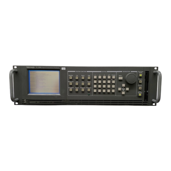
TG 2000
Tektronix TG 2000 Generation Platform Manuals
Manuals and User Guides for Tektronix TG 2000 Generation Platform. We have
1
Tektronix TG 2000 Generation Platform manual available for free PDF download: User Manual
Tektronix TG 2000 User Manual (283 pages)
Signal Generation Platform
Brand:
Tektronix
| Category:
Portable Generator
| Size: 1 MB
Table of Contents
Table of Contents
6
General Safety Summary
16
Service Safety Summary
18
Preface
20
Getting Started
23
Product Description
23
Accessories
24
BG1 Black Burst Generator Module
24
SDP2000 Signal Development Program
24
GPIB Card for SDP2000 Communications
25
Accessory Kit
25
Configuration
25
Line Voltage Setting and Fuse Selection
25
Figure 1-1: Location of Power Connections and Configuration
26
Table 1-1: AC Power Fuse Requirements
26
CPU Configuration Switch
27
Figure 1-2: Location of the Service Diagnostics Switch
27
Installation
28
Hardware Installation
28
Rackmount Installation
28
Figure 1-3: Installing the Rackmount Hardware
29
Software Installation
30
Figure 1-4: Placing the TG 2000 Signal Generation Platform in the Rack
30
Power-On Procedure
31
Incoming Inspection
32
Equipment Needed
32
Incoming Inspection Procedure
32
Figure 1-5: Hooking up the Clock Output to the Frequency Counter
35
Functional Overview
38
System Control
38
Disk Drive
38
Remote Control
38
Generator Modules
39
Signal Memory
39
Figure 2-1: TG 2000 Signal Generation Platform Simplified Block Diagram
39
Black Burst Module
40
Battery Backup for NVRAM
40
Clocks and Frame Reset Signals
40
External Reference Genlock
41
Timing References
41
Figure 2-2: Block Diagram of the Clocks and Frame Reset Signals
41
Module Timing Delay
42
Figure 2-3: Comparison of Module Delay and System Delay from a Reference
42
System Reference Delay with the AGL1 Module
43
Figure 2-4: Block Diagram of Module Timing Delay
43
Test Signals
44
Figure 2-6: Module and Test Signal Hierarchy
44
Shared Module Memory
45
Front Panel Overview
46
Brief Description of the Front Panel Controls
46
Figure 2-7: TG 2000 Signal Generation Platform Front Panel
46
Touch Screen and Front-Panel Controls
47
Touch Screen Display
47
Figure 2-8: Main Display Features
47
System Function Windows
49
Cursor Buttons and Knob
53
Figure 2-9: Browsed and Selected Icons
53
Figure 2-10: Using the Knob to Open a List of Signals
54
Keypad
55
Table 2-1: Keypad Definitions
55
Operating Procedures
58
Allocating System Resources
58
Clock Allocation
58
Frame Reset Allocation
59
Calibration
60
Date/Time Set
60
Front Panel Enable and Timeout
61
Help
62
Locked LED
63
Module Status
64
Presets
65
Create a Preset
65
Save Current Settings to an Existing Preset
66
Recall, Rename, or Delete a Preset
66
References
67
Module Timing
67
Select Reference
69
Reference Timing
70
Selecting Internal or External Reference
70
Renaming a Module
71
Self Calibration
72
Sequences
73
Add Sequence from Disk
73
Run a Sequence
74
Stop a Sequence
74
Screen Contrast
75
Selecting Test Signals
75
Versions
76
Syntax
79
Programming Model
79
Addressing Module Test Signals
79
Command Arguments
79
Argument Example
80
SCPI Commands and Queries
82
Creating Commands
82
Creating Queries
82
Figure 3-1: Example of SCPI Subsystem Hierarchy
82
Parameter Types
83
Table 3-1: Parameter Types Used in Syntax Descriptions
83
Abbreviating Commands, Queries, and Parameters
84
Chaining Commands and Queries
84
Figure 3-2: Example of Abbreviating a Command
84
General Rules
85
Figure 3-3: Example of Chaining Commands and Queries
85
Figure 3-4: Example of Omitting Root and Lower-Level Nodes in a Chained Message
85
IEEE 488.2 Common Commands
87
Command and Query Structure
87
Backus-Naur Form Definition
87
Message Terminators
87
Constructed Mnemonics
88
Block Arguments
88
Special Characters
89
Sequence Programming
91
Writing a Sequence Program
91
Sample Program 1
92
Sample Program 2
94
Sample Program 3
96
Next Module
96
Next Signal Set
96
Next Signal
96
Previous Signal
96
Internal Sync
96
External Sync
96
Stop Sequence
96
Reset Sequence
96
Running a Sequence
103
Autostart Files
103
Tcl Programming Changes
104
Functional Command Groups
106
Common
106
Calibration
106
Table 3-2: * Common Commands
106
Table 3-3: :Calibration Commands
106
Table 3-4: :Display Commands
107
Table 3-5: :Instrument Commands
107
Table 3-6: :Mmemory Commands
108
Sense:roscillator:frame2:Frequency
109
Table 3-7: :Program Commands
109
Table 3-8: :Sense Commands
109
Command Tree
125
Condition
189
Enable(?)
190
Ptransition(?)
191
Ntransition(?)
192
Map(?)
193
Instrument(?)
194
Gclosure
195
Registers
206
Figure 4-1: the Status Byte Register (SBR)
207
Table 4-1: SRB Bit Functions
207
Figure 4-2: the Standard Event Status Register (SESR)
208
Table 4-2: SESR Bit Functions
208
Figure 4-3: the Event Status Enable Register (ESER)
210
Figure 4-4: the Service Request Enable Register (SRER)
210
Queues
211
Figure 4-5: Status and Event Processing Sequence
212
Messages
213
Table 4-3: Command Errors
216
Table 4-4: Execution Errors
217
Table 4-5: Device Specific Errors
219
Query Errors
220
Device Errors
220
Table 4-6: Query Errors
220
Table 4-7: Device Errors
220
Specifications
223
Table A-1: AC Power Source
223
Table A-2: Physical Dimensions
223
Table A-3: Environmental Characteristics
224
Table A-4: System Clock and Frame Reset
224
Table A-5: Certifications and Compliances
225
Table B-1: SCPI Conformance Information
227
Figure D-1: Rear Panel Remote Connectors
250
Figure D-2: RS-232 Connector Pin Assignments
251
Figure D-3: Serial Port Ground Closure Functions
251
Figure D-4: Sample Ground Closure Control Panel
252
Table E-1: Module Slot Assignments
260
Advertisement
Advertisement
Related Products
Tektronix TG700
Tektronix TSG4106A
Tektronix TR 502
Tektronix TM 506
Tektronix TSG4100A-RM1
Tektronix TSG4100A-RM2
Tektronix TSG 95
Tektronix TSG200
Tektronix TSG-271
Tektronix TSG4
Tektronix Categories
Test Equipment
Measuring Instruments
Amplifier
Portable Generator
Printer
More Tektronix Manuals
Login
Sign In
OR
Sign in with Facebook
Sign in with Google
Upload manual
Upload from disk
Upload from URL