Table of Contents
Advertisement
Quick Links
Advertisement
Chapters
Table of Contents

Related Manuals for Tektronix HDLG7


Summary of Contents for Tektronix HDLG7
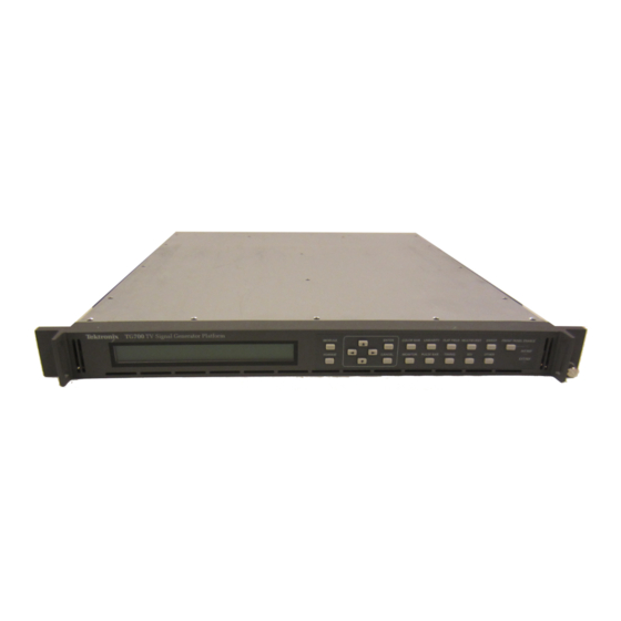
- Page 1 TG700 TV Signal Generator Platform User Manual *P071197003* 071-1970-03...
- Page 3 TG700 TV Signal Generator Platform User Manual This document supports software version 5.4 and above. www.tektronix.com 071-1970-03...
- Page 4 Copyright © Tektronix. All rights reserved. Licensed software products are owned by Tektronix or its subsidiaries or suppliers, and are protected by national copyright laws and international treaty provisions. Tektronix products are covered by U.S. and foreign patents, issued and pending. Information in this publication supersedes that in all previously published material.
- Page 5 Tektronix, with shipping charges prepaid. Tektronix shall pay for the return of the product to Customer if the shipment is to a location within the country in which the Tektronix service center is located. Customer shall be responsible for paying all shipping charges, duties, taxes, and any other charges for products returned to any other locations.
- Page 6 2. Transfer the Program to any person or organization outside of Customer or the corporation of which Customer is a part without the prior written consent of Tektronix, except in connection with the transfer of the equipment within which the programs are encoded or incorporated;...
- Page 7 The license may be terminated by Customer at any time upon written notice to Tektronix. The license may be terminated by Tektronix or any third party from whom Tektronix may have obtained a respective licensing right if Customer fails to comply with any term or condition and such failure is not remedied within thirty (30) days after notice hereof from Tektronix or such third party.
- Page 8 In order to obtain service under this warranty, Customer must notify Tektronix of the defect before the expiration of the warranty period. If Tektronix is unable to provide a replacement that is free from defects in materials and workmanship within a reasonable time thereafter, Customer may terminate the license for the Program and return the Program and any associated materials for credit or refund.
-
Page 9: Table Of Contents
Table of Contents General Safety Summary ..................Service Safety Summary..................Compliance Information ..................xiii EMC Compliance.................... xiii Safety Compliance................... Environmental Considerations ................Preface ......................xvii Products...................... xvii About This Manual ..................xvii Related Manuals ................... xviii Getting Started Getting Started ....................Product Description.................. - Page 10 Table of Contents Modules AG7 Audio Generator Module.................. Product Description..................Operating Procedure..................AG7 Module Main Menu ................... Factory Default Settings ..................AGL7 Analog Genlock Module ................Product Description..................Operating Procedure..................AGL7 Module Main Menu ................. Factory Default Settings .................. 3-17 ATG7 Analog Test Generator .................
- Page 11 Zone Plate Dependent Parameters ..............3-154 Using Zone Plate Signals ................3-160 HD3G7 Module Main Menu ................3-161 Factory Default Settings ................. 3-186 HDLG7 HD Dual Link Video Generator ..............3-189 Product Description..................3-189 Operating Procedure..................3-190 Selecting an Output Signal................3-191 HDLG7 Module Main Menu ................
- Page 12 Figure 2-11: DVG7 module connectors (Option BK) ............Figure 2-12: GPS7 module connectors ..............2-10 Figure 2-13: HD3G7 module connectors ..............2-12 Figure 2-14: HDLG7 module connectors..............2-13 Figure 2-15: HDVG7 module connectors (Option BK)............ 2-13 Figure 2-16: Mainframe main menu .................
- Page 13 Table of Contents Figure 3-1: AG7 module main menu................Figure 3-2: AG7 module CHANNEL PARAMETERS submenu........... Figure 3-3: AG7 module AUDIO TIMING submenu............Figure 3-4: AGL7 module main menu ................. Figure 3-5: AGL7 module GENLOCK submenu............3-10 Figure 3-6: AGL7 module OUTPUT submenu ............. 3-12 Figure 3-7: AGL7 module SIGNAL submenu ..............
- Page 14 Table of Contents Figure 3-42: DVG7 module main menu ..............3-80 Figure 3-43: DVG7 module MOVING PICTURE submenu ..........3-81 Figure 3-44: DVG7 module OVERLAY submenu ............3-82 Figure 3-45: DVG7 module LOGO submenu............... 3-83 Figure 3-46: DVG7 module ID TEXT submenu............3-84 Figure 3-47: DVG7 module CIRCLE submenu ............
- Page 15 3-193 Figure 3-97: HDLG7 module main menu ..............3-198 Figure 3-98: HDLG7 module LINK OFFSET submenu..........3-200 Figure 3-99: HDLG7 module MOVING PICTURE submenu ........... 3-201 Figure 3-100: Front-panel test signal buttons .............. 3-206 Figure 3-101: HDVG7 module main menu..............
- Page 16 Table of Contents List of Tables Table 1-1: Standard and optional accessories ..............Table 1-2: Instrument and module options ..............Table 1-3: TG700 environmental requirements ............... Table 1-4: AC line power requirements................ Table 2-1: GPS7 module LTC/GPI connector pin assignments ........... 2-11 Table 2-2: Mainframe GPI jumper settings on the A10 MAIN board ........
- Page 17 3-192 Table 3-34: HDLG7 module HD test signal set assigned to the test signal buttons....3-194 Table 3-35: HDLG7 module projector test pattern set assigned to the test signal buttons .... 3-194 Table 3-36: HDLG7 module sample structure/depth signal formats........
-
Page 18: General Safety Summary
General Safety Summary General Safety Summary Review the following safety precautions to avoid injury and prevent damage to this product or any products connected to it. To avoid potential hazards, use this product only as specified. Only qualified personnel should perform service procedures. To Avoid Fire or Personal Use proper power cord. - Page 19 General Safety Summary Terms in This Manual These terms may appear in this manual: WARNING. Warning statements identify conditions or practices that could result in injury or loss of life. CAUTION. Caution statements identify conditions or practices that could result in damage to this product or other property.
-
Page 20: Service Safety Summary
Service Safety Summary Service Safety Summary Only qualified personnel should perform service procedures. Read this Service Safety Summary and the General Safety Summary before performing any service procedures. Do Not Service Alone. Do not perform internal service or adjustments of this product unless another person capable of rendering first aid and resuscitation is present. -
Page 21: Compliance Information
IEC 61000-4-11:2004. Voltage dips and interruptions immunity EN 55103-2:1996 Annex A Radiated magnetic field immunity EN 61000-3-2:2006. AC power line harmonic emissions EN 61000-3-3:1995. Voltage changes, fluctuations, and flicker European Contact. Tektronix UK, Ltd. Western Peninsula Western Road Bracknell, RG12 1RF United Kingdom... -
Page 22: Safety Compliance
Refer to the EMC specification published for the stated products. May not meet the intent of the directive if used with other products. European Contact. Tektronix UK, Ltd. Western Peninsula Western Road Bracknell, RG12 1RF United Kingdom To ensure compliance with the EMC standards listed here, high quality shielded interface cables should be used. - Page 23 Compliance Information Safety Class Class 1 – grounded product. Safety Certification of The safety certification is valid only when installed in an appropriately approved (by a USA NRTL or a Canada Certified Organization) mainframe. Plug-in Modules Pollution Degree A measure of the contaminants that could occur in the environment around and within a product.
-
Page 24: Environmental Considerations
Union requirements according to Directives 2002/96/EC and 2006/66/EC on waste electrical and electronic equipment (WEEE) and batteries. For information about recycling options, check the Support/Service section of the Tektronix Web site (www.tektronix.com). Restriction of Hazardous This product has been classified as Monitoring and Control equipment, and is outside the scope of the 2002/95/EC RoHS Directive. -
Page 25: Preface
DVG7 Digital Video Generator Module GPS7 GPS Synchronization and Timecode Module HD3G7 HD 3 Gb/s SDI Video Generator Module HDLG7 HD Dual Link Generator Module HDVG7 HDTV Digital Video Generator Module About This Manual This manual is composed of the following sections: Getting Started shows you how to configure and install your TG700 system... -
Page 26: Related Manuals
The following documents are also available for the TG700: The TG700 TV Signal Generator Platform PC Tools Technical Reference (Tektronix part number 077-0138-XX) describes how to use the PC tools that are available for the mainframe and related modules. The TG700 TV Signal Generator Platform Specifications and Performance Verification Technical Reference (Tektronix part number 077-0137-XX) -
Page 27: Getting Started
Getting Started... -
Page 29: Product Description
ATC (HDVG7) when a GPS7 module is installed Timecode generator with ATC (HD3G7) with or without a GPS7 module Dual link SDI generator and converter (HDLG7) 3 Gb/s SDI video generator and converter (HD3G7) Independent setting of amplitudes, frequencies, and audio clicks of 16 channel... -
Page 30: Mainframe Memory Requirements
If you have an older mainframe with less than 64 MB of memory, you can increase the memory in your mainframe to 64 MB by ordering the following upgrade kit: 040-1698-xx. Contact your local Tektronix representative for more information. 1–2... -
Page 31: Accessories
When you order Option D1, a Calibration Test Data TG700 mainframe, Report is provided with the instrument and/or module for AG7, AGL7, ATG7, which the option is specified. AVG7, AWVG7, GPS7, HD3G7, HDLG7, HDVG7 TG700 TV Signal Generator Platform User Manual 1–3... - Page 32 TG700 mainframes. If you have an older mainframe with less than 64 MB of memory, you can upgrade your mainframe to 64 MB by ordering the following upgrade kit: 040-1698-xx. Contact your local Tektronix representative for more information.
-
Page 33: Initial Product Inspection
(See Table 1-1.) Contact your local Tektronix Field Office or representative if there is a problem with your instrument or if your shipment is incomplete. -
Page 34: Figure 1-1: Installing The Rackmount Hardware
Getting Started Figure 1-1: Installing the rackmount hardware 1–6 TG700 TV Signal Generator Platform User Manual... -
Page 35: Figure 1-2: Placing The Tg700 In The Rack
Getting Started The following figure shows how to install the TG700 into the rack. Carefully insert the rack slides attached to the TG700 into the pieces attached to the rack. Support the TG700 until the stop latches click into place on both sides. The installation is not secure until this latching occurs. -
Page 36: Table 1-4: Ac Line Power Requirements
After connecting the power, make sure that the fan on the rear panel is working. If the fan is not working, turn off the power by disconnecting the power cable from the AC power source, and then contact your local Tektronix Field Office or representative. -
Page 37: Module Installation And Removal
Getting Started Module Installation and Removal The following procedures describe how to install and remove modules from the TG700 mainframe. A screwdriver with a #1 Phillips tip is the only tool you need to install or remove a module. CAUTION. To prevent damage to the mainframe and module, always remove the power cord before installing or removing a module. -
Page 38: Figure 1-3: Tg700 Slot Numbering
TG700 mainframe oven calibration. (See page 2-28, CAL OVEN Submenu.) For AG7, ATG7, AVG7, BG7, DVG7, and HDLG7 modules, up to four of the modules can be installed in the TG700 mainframe. The HD3G7, AWVG7, and HDVG7 modules consume higher power than most of the TG700 modules. -
Page 39: Figure 1-4: Removing The Blank Panel
Getting Started Figure 1-4: Removing the blank panel CAUTION. Be careful not to damage the parts and cables inside of the module when you insert the module into the mainframe. 4. Insert the module into the slot, paying attention to the module orientation. (See Figure 1-5.) Push the module into the slot until the connector board of the module is firmly engaged with the Main board of the mainframe. -
Page 40: Figure 1-6: Securing The Module
Getting Started Figure 1-6: Securing the module Removing a Module To remove a module from the mainframe, perform the following procedure: CAUTION. To facilitate module removal, attach terminations or BNC cables to the module connectors. The connector may be damaged if too much force is applied to it during module removal. -
Page 41: Functional Checks
Getting Started Figure 1-7: Removing the module 5. If this empty slot will not be used, you must attach a blank panel to the mainframe to control instrument cooling and EMI emissions. a. Align the blank panel with the open slot of the mainframe. b. - Page 42 Getting Started 75 Ω BNC cable 75 Ω Termination Procedure. 1. Install the module into the TG700 mainframe. (See page 1-9.) 2. Power on the TG700 mainframe by connecting it to the power source. The initialization process for all installed modules is executed. 3.
- Page 43 Getting Started HDTV waveform monitor 75 Ω BNC cable 75 Ω termination Procedure. 1. Install the module into the TG700 mainframe. (See page 1-9.) 2. Power on the TG700 mainframe by connecting it to the power source. The initialization process for all installed modules is executed. 3.
- Page 44 Getting Started Black Signal Outputs. 14. Press the front-panel CANCEL button. 15. Press the up (▲) or down (▼) arrow button to select SELECT OUTPUT from the main menu. 16. Press the left (◄) or right (►) arrow button to select BLACK 1, then press the ENTER button.
- Page 45 Getting Started ATG7 Module Functional Use the following procedure to check that the ATG7 Analog Test Generator module is functional. Check Required Equipment. NTSC/PAL waveform monitor 75 Ω BNC cable 75 Ω terminator NOTE. If the software version of your TG700 mainframe is version 1.3 or earlier, you must upgrade the software of the mainframe before using the ATG7 module.
- Page 46 Getting Started BLACK 1 and BLACK 2 Outputs. 12. Disconnect the BNC cable from the SIGNAL connector, and then connect it to the BLACK 1 connector. 13. Press the up (▲) or down (▼) arrow button to select SELECT OUTPUT from the main menu.
- Page 47 Getting Started 31. Set the waveform monitor to view the color bars signal. 32. Check that the appropriate color bars signal appears. AVG7 Module Functional Use the following procedure to check that the AVG7 Analog Video Generator module is functional. Check Required Equipment.
- Page 48 Getting Started 13. Check that the signal appears as expected. For example, if you selected a color bar signal in step 7, check that the color bar signal appears. 14. Disconnect the BNC cable from the CH 1 connector, and then connect the BNC cable to the CH 2 connector.
- Page 49 Getting Started 7. Press one of the front-panel test signal buttons (for example COLOR BAR) to output a signal. 8. Use the 75 Ω BNC cables to connect the upper (or lower) CH 1, CH 2, and CH 3 connectors to the CH A, CH B, and CH C inputs of the waveform monitor respectively.
- Page 50 Getting Started Procedure. 1. Install the module into the TG700 mainframe. (See page 1-9.) 2. Power on the TG700 mainframe by connecting it to the power source. The initialization process for all installed modules is executed. 3. Check that no error messages appear on the LCD display. 4.
- Page 51 Getting Started 18. Check that the appropriate HDTV trilevel sync signal is displayed. 19. Repeat this procedure for the BLACK 2, BLACK 3, and BLACK 4 outputs. DVG7 Module Functional Use the following procedure to check that the DVG7 Digital Video Generator module is functional.
- Page 52 Female XLR connector, three wires, and one 9-pin DSUB male header with solder cups, assembled as described in the LTC Output test BNC-to-banana-plug adapter (2) 75 Ω coaxial terminators (Tektronix part number 011-0163-XX) (2) BNC T connectors (3) 1 meter BNC cables Procedure.
- Page 53 Getting Started 5. Run the GPS7 module diagnostics: a. Press the MODULE button until GPS7 appears. b. Use the up (▲) or down (▼) arrow button to select DIAGNOSTICS. c. Press the ENTER button. d. Use the left (◄) or right (►) arrow button to scroll through the menu. Take note of any errors or warnings.
- Page 54 Getting Started Antenna current and fault thresholds. 1. Connect the BNC-to-Banana-plug adapter to the voltmeter. 2. Connect the BNC T to the adapter. 3. Set the antenna power to 5 V: a. Press the MODULE button to navigate to the GPS7 module. b.
- Page 55 Getting Started 1. Set the antenna voltage as needed by the antenna in the test system. 2. Navigate to the signal quality menu: a. Press the MODULE button to navigate to the GPS7 module. b. Use the up (▲) or down (▼) arrow button to select STATUS from the GPS7 module menu.
- Page 56 Getting Started 4. Set Black 1 to NTSC on the GPS7 module: a. Use the up (▲) or down (▼) arrow button to SELECT OUTPUT. b. Use the left (◄) or right (►) arrow button to select Black 1. c. Press the ENTER button. d.
- Page 57 Getting Started 19. Press the CANCEL button again to exit the Select Format submenu. 20. Disconnect the Black 2 signal from the module and the WFM7120. 21. Connect the Black 3 signal from the module to the reference input of the WFM7120.
- Page 58 Getting Started 11. Press the ENTER button. 12. Press the CANCEL button to exit the NTSC submenu. 13. Use the up (▲) or down (▼) arrow button to select Timecode. 14. Press the ENTER button. 15. Use the left (◄) or right (►) arrow button to select Time of Day as the Timecode Source.
- Page 59 Getting Started 6. Configure the LTC 1 output of the GPS7 module for 30 fps drop frame: a. Press the MODULE button until GPS7 appears. b. Use the up (▲) or down (▼) arrow button to select LTC. c. Press the ENTER button. d.
- Page 60 Getting Started 3. Configure the GPI 1 output to be asserted on unlock: a. Press the MODULE button until GPS7 appears. b. Use the up (▲) or down (▼) arrow button to select SELECT GPIO. c. Press the ENTER button. d.
- Page 61 Getting Started Genlock. 1. Set the Reference Source to Internal. a. Use the up (▲) or down (▼) arrow button to select REFERENCE. b. Press the ENTER button. c. If needed, use the up (▲) or down (▼) arrow button to select SOURCE. d.
- Page 62 Getting Started Generator Function. 4. Press the front-panel MODULE button until the HD3G7 main menu shown below appears. 5. Press the down (▼) arrow button to select Output Mode, and then use the left (◄) or right (►) arrow button to select the desired output mode. When the desired output mode is displayed, press the Enter button to confirm it.
- Page 63 Getting Started Converter Function. 21. Set the HDTV video generator as indicated below: Output signal: Ramp Format: 1080 59.94i 22. Press the front-panel MODULE button until the HD3G7 main menu shown below appears. 23. Connect the output connector on the HDTV video generator to the HD SDI IN connector on the HD3G7 using the 75 Ω...
- Page 64 Getting Started HDLG7 Module Functional Use the following procedure to check that the HDLG7 HD Dual Link Video Generator module is functional. Check Required Equipment. HDTV digital video generator HDTV waveform monitor Three 75 Ω BNC cables Procedure. 1. Install the module into the TG700 mainframe. (See page 1-9.) 2.
- Page 65 18. Connect the output connector on the HDTV digital video generator to the HD SDI IN connector on the HDLG7 using the 75 Ω BNC cable. 19. Press the FORMAT button and use the left (◄) or right (►) arrow button to select 1080 59.94p, and then press the ENTER button.
- Page 66 Getting Started 4. Warm up the instrument for 20 minutes. 5. Press the front-panel MODULE button until the HDVG7 main menu shown below appears. 6. Press the FORMAT button and use the left (◄) or right (►) arrow button to select a format, then press ENTER.
-
Page 67: Operating Basics
Operating Basics... -
Page 69: Front-Panel Controls
Operating Basics This section introduces you to the basics of operating the TG700. Common module functions are discussed here, while module-specific functions are discussed in the module-specifc sections of this manual. This section contains the following topics: Front-panel controls Rear-panel connectors About the frame reset signals Note for format settings Front-Panel Controls... - Page 70 Operating Basics FORMAT Button When the ATG7, AVG7, AWVG7, DVG7, HD3G7, HDLG7, or HDVG7 module is selected (active), use the FORMAT button to change the video format for the output signal. Pressing this button displays the menu to allow you to select a format for the active module.
-
Page 71: Rear-Panel Connectors
Operating Basics Rear-Panel Connectors The following figure shows the locations of the TG700 mainframe and module connectors on the rear panel. A brief discussion of each connector follows the illustration. CAUTION. If power is applied to the mainframe, be sure to terminate any unused outputs on any of the modules using 75 Ω... -
Page 72: Figure 2-3: Ag7 Module Connectors
Operating Basics AG7 Module Connectors The AG7 Audio Generator module is equipped with six BNC connectors as described below. (See Figure 2-3.) Figure 2-3: AG7 module connectors 1+2: Outputs channels 1 and 2 of the selected AES/EBU serial digital audio signal. -
Page 73: Figure 2-4: Location Of J452 On The Ag7 Module
Operating Basics Install the jumper on pins 3+4 of J452 (factory-default position) to set the clock output level to CMOS compatible. Install the jumper on pins 1+2 of J452 to set the clock output level to 1V. Figure 2-4: Location of J452 on the AG7 module AGL7 Module Connectors The AGL7 Analog Genlock module is equipped with six BNC connectors as described below. - Page 74 Operating Basics BLACK 2: Outputs the selected black burst or HDTV trilevel sync signal. BLACK 3: Outputs the selected black burst signal or HDTV trilevel sync signal. Alarm Output. When the mainframe GPI interface is enabled, you can configure the BLACK 1, BLACK 2, or BLACK 3 connector to output an alarm. When an alarm condition is detected, the output signal from the selected connector turns off for about 60 ms.
-
Page 75: Figure 2-6: Location Of J040 And J960 On The Agl7 Module
Operating Basics Figure 2-6: Location of J040 and J960 on the AGL7 module ATG7 Module Connectors The ATG7 Analog Test Generator module is equipped with four BNC connectors as described below. (See Figure 2-7.) Figure 2-7: ATG7 module connectors BLACK 1: Outputs the selected black burst, timing pulse, or subcarrier signal. -
Page 76: Figure 2-8: Avg7 Module Connectors
Operating Basics AVG7 Module Connectors The AVG7 Analog Video Generator module is equipped with three pairs of BNC connectors as described below. (See Figure 2-8.) Figure 2-8: AVG7 module connectors NOTE. Each pair of connectors (CH 1, CH 2, and CH 3) output the same signal. CH 1: Outputs the selected analog component or composite video signal. -
Page 77: Figure 2-10: Bg7 Module Connectors
Operating Basics BG7 Module Connectors The BG7 Black Generator module is equipped with four BNC connectors as described below. (See Figure 2-10.) Figure 2-10: BG7 module connectors BLACK 1: Outputs the selected black burst or HDTV trilevel sync signal. BLACK 2: Outputs the selected black burst or HDTV trilevel sync signal. BLACK 3: Outputs the selected black burst or HDTV trilevel sync signal. -
Page 78: Figure 2-12: Gps7 Module Connectors
Operating Basics BLACK 1: Outputs the selected serial digital black signal (Option BK only). BLACK 2: Outputs the selected serial digital black signal (Option BK only). NOTE. The SIGNAL 1 and SIGNAL 2 connectors output the same test signal, and the BLACK 1 and BLACK 2 connectors output the same black signal. -
Page 79: Table 2-1: Gps7 Module Ltc/Gpi Connector Pin Assignments
Operating Basics the GPS7 module. The LTC/GPI connector provides partial functionality when you use a standard RGBHV (VGA-to-BNC) breakout cable. (See Table 2-1.) NOTE. You do not need the optional LTC and GPI breakout cable if you are using only VITC and/or ATC as a timecode signal. For correct operation if you use a VGA-to-BNC breakout cable, pins 6, 7, 8, and 10 must be internally grounded together in the cable and to the connector shell. -
Page 80: Figure 2-13: Hd3G7 Module Connectors
Operating Basics detected. The output will remain off as long as the error occurs. Use this function to trigger a downstream ECO to switch to backup. BLACK 3 / 10 MHz: Outputs the selected black burst or HDTV trilevel sync signal. -
Page 81: Figure 2-14: Hdlg7 Module Connectors
Operating Basics HDLG7 Module Connectors The HDLG7 HD Dual Link Video Generator is equipped with five BNC connectors as described below. (See Figure 2-14.) Figure 2-14: HDLG7 module connectors HD SDI IN: Input connector for an HD-SDI (4:2:2) video signal that you want to be upconverted. -
Page 82: Frame Reset Signals
1080 24sF 25 fps LTC 30 fps LTC HD3G7 and HDLG7 only. Not drop frame The frequency of frame reset signal 2 is always an integral multiple of the frame reset signal 3 frequency. Frame reset signal 3 is synchronized with frame reset signal 2. -
Page 83: Clock Conflict Messages
Operating Basics Frame reset signal 1 is not synchronized with frame reset signals 2 or 3 unless a GPS7 module is installed. When a GPS7 module is installed, the frame reset signal 1 synchronization is related to the frame reset signals 2 and 3 through the GPS7 epoch timing. -
Page 84: Fan Failure Warning Message
AGL7 output(s) that were using the clock you disabled. CAUTION. The HDLG7 module does not generate the Clock Select warning message when you change the signal format on the HDLG7 module and create a clock conflict with other modules using the HD clock. Fan Failure Warning Message CAUTION. -
Page 85: Using The Mainframe Menus
The TG700 displays the following warning message if the fan on the rear panel stops working. If this warning message appears, disconnect the power cable from the AC voltage line and contact your local Tektronix Field Office or representative. While the warning message appears, the front-panel buttons are disabled. You can operate the buttons temporarily by pressing the FRONT PANEL ENABLE button until the indicator next to the button lights. - Page 86 Operating Basics SEQUENCE. Selects and executes a sequence program loaded into the TG700. Select this menu item and press the ENTER button, to access the SEQUENCE submenu. (See page 2-20.) FRAME RESET STATUS. Displays the status of the frame reset signals. Select this menu item and press the ENTER button to access the FRAME RESET STATUS submenu.
-
Page 87: Figure 2-17: Preset Submenu
Operating Basics Figure 2-17: PRESET submenu RECALL. Recalls instrument settings saved in the selected preset. Use the left (◄) or right (►) arrow button to select a different preset, and then press the ENTER button to implement the selection. While the preset is loading into the instrument, the message "Now Loading ..." appears on the display. -
Page 88: Figure 2-18: Sequence Submenu
Operating Basics 5. Enter all of the desired characters then press ENTER button. 6. Press the CANCEL button twice to exit the PRESET submenu. This returns to the top of the mainframe main menu. 7. Press the ENTER button to reenter the PRESET submenu. 8. -
Page 89: Figure 2-19: Frame Reset Status Submenu
Operating Basics FRAME RESET STATUS Use this menu to display which of the three frame reset signals is used by the output of the installed modules. Use the up (▲) or down (▼) arrow button to Submenu scroll through the menu items. The following figure shows the FRAME RESET STATUS submenu. -
Page 90: Figure 2-20: Utility Submenu
Operating Basics UTILITY Submenu Use this menu to set the system-related settings such as the contrast of the LCD display and the network parameters. Use the up (▲) or down (▼) arrow button to scroll through the menu items. The following figure shows the UTILITY submenu. - Page 91 Operating Basics VERSION INFO (H/W). Displays the hardware version of the mainframe and the installed modules. Use the left (◄) or right (►) arrow button to select the module for which you want to display the hardware version. VERSION INFO (F/W). Displays the firmware version number of the mainframe and the installed modules.
-
Page 92: Figure 2-21: Signal Key Assign Submenu
Operating Basics SIGNAL KEY ASSIGN Use this menu to assign signal sets to a specific front-panel test signal button. If your mainframe has 64 MB of memory installed, you can also assign a frame Submenu picture file created by the Frame Picture Generator to the OTHER test signal button. -
Page 93: Figure 2-22: Network Information Submenu
Operating Basics FRAME PICTURE KEY ASSIGN. Assigns frame picture files downloaded to the TG700 to the OTHER test signal button. This operation is required to output the frame picture files as a picture (natural picture or test pattern). NOTE. To download a frame picture file created by the Frame Picture Generator application and output it as a picture, your TG700 mainframe must have 64 MB of memory installed. -
Page 94: Figure 2-23: Network Setup Submenu
Operating Basics NETWORK SETUP Use this menu to set the network parameters for the 10 BASE-T port on the TG700, which will be used when you remotely control the TG700 using a PC Submenu and when you transfer files between the TG700 and a PC. Refer to Connecting to a Network for detailed information about connecting the TG700 to a PC. - Page 95 Operating Basics IP ADDRESS. Sets the IP address of the TG700. When no value is set, the default value is used. If DHCP service is enabled, the IP address obtained from the DHCP server is used instead of the address entered here. Refer to Manually Setting a Network Address below for instructions on how to enter an address.
-
Page 96: Figure 2-24: Diagnostics Submenu
GPS7 module has its own diagnostics submenu; running the diagnostics here does not run the GPS7 diagnostics). If all of the diagnostic routines are completed without any errors, the instrument will display "Pass". If a diagnostic error is displayed, contact your local Tektronix Field Office or representative. NOTE. -
Page 97: Figure 2-25: Internal Frequency Calibration Menu
Operating Basics The mainframe oscillator is calibrated by storing the current frequency of the oscillator while it is locked to a GPS or a reference video signal. This stored frequency value is used when the instrument boots up and when there is a loss of signal lock and the instrument is configured to switch to internal timing. -
Page 98: Connecting To A Network
Operating Basics Connecting to a Network The TG700 has a 10 BASE-T port on the rear panel that allows you to use a PC to remotely control the instrument and to upload and download files such as signal or logo files. This section provides instructions for connecting the TG700 to a single PC or to a network, and for setting the network parameters on 10 BASE-T port. - Page 99 Operating Basics 3. Use the up (▲) or down (▼) arrow button to select Network. 4. Use the left (◄) or right (►) arrow button to select Setup. This accesses the NETWORK SETUP submenu. (See Figure 2-23 on page 2-26.) Setting the Parameters on a Network with a DHCP Server.
-
Page 100: Using The Mainframe General Purpose Interface (Gpi)
Operating Basics Using the Mainframe General Purpose Interface (GPI) You can use the 10 BASE-T port of the TG700 mainframe as a General Purpose Interface (GPI) by changing internal jumper settings. When you enable the mainframe GPI, you can recall one of the seven available presets, output an alarm signal, and display an alarm status on the LCD. -
Page 101: Figure 2-28: Top Cover Removal
Operating Basics Figure 2-28: Top cover removal 4. Locate the connectors J000, J002, J004, J006, and J008 on the A10 MAIN board. (See Figure 2-29.) Figure 2-29: Location of the mainframe GPI connectors on the A10 MAIN board 5. Move all of the jumpers from pins 1-2 to pins 2-3. The following table shows the jumper settings of the connectors and their function. -
Page 102: Figure 2-30: Applying The Mainframe Gpi Label To The Rear Panel
Operating Basics Table 2-2: Mainframe GPI jumper settings on the A10 MAIN board Jumper illustration Jumper setting Function All of the jumpers short pins 1-2. LAN (Ethernet) (factory default settings) All of the jumpers short pins 2-3. 6. After you move the jumpers, replace the top cover on the instrument. 7. -
Page 103: Table 2-3: Pin Assignments Of The 10 Base-T Connector For The Mainframe Gpi
Operating Basics Table 2-3: Pin assignments of the 10 BASE-T connector for the mainframe GPI Pin number Function Level 1, 2, and 3 Input High > 1.4 V or open (connected to an internal 10 kΩ pull-up resistor) Low < 0.4 V or ground (input impedance: 10 kΩ) Low <... - Page 104 Operating Basics Outputting an Alarm Signal When you enable the mainframe GPI, the TG700 can output an alarm signal from pin 6 on the 10 BASE-T connector when an internal error occurs. Since the output signal is an active low; the signal level for pin 6 goes from High to Low when any errors occur.
-
Page 105: Figure 2-31: Mainframe Gpi Alarm Menu
Operating Basics Use the ALARM menu items to enable or disable the alarm signal output, to reset the alarm signal output, or to display the alarm status. The following figure shows the ALARM menu. Figure 2-31: Mainframe GPI ALARM menu TG700 TV Signal Generator Platform User Manual 2–37... - Page 106 Operating Basics The ALARM menu contains the following selections: ALARM STATUS: Displays the alarm status detected inside the instrument. The following status messages may be displayed. No Alarm: No errors have been detected. Genlock: Near Loss of Lock: The frequency of the genlock signal and the internal reference signal have shifted considerably, and the TG700 is near loss of lock.
- Page 107 Operating Basics you select Disable, the alarm output to the AGL7 module is disabled. Press the ENTER button to confirm the selection. NOTE. The AGL7 module alarm output is available only when the GPI ALARM OUTPUT menu item is set to Enable. AGL7 ALARM SELECT: Selects which of the AGL7 alarms are enabled or disabled.
- Page 108 Operating Basics Loss of Lock: Enables or disables the mainframe GPI alarm when the TG700 does not lock to a genlock signal. Use the left (◄) or right (►) arrow button to select between Enable and Disable. Press the ENTER button to implement the selection.
-
Page 109: Inspection And Cleaning
Operating Basics arrow button to select between Enable and Disable. Press the ENTER button to implement the selection. Inspection and Cleaning Inspect and clean the instrument as often as your operating conditions require. The collection of dirt can cause instrument overheating and operational failure. Dirt acts as an insulating blanket, preventing efficient heat dissipation. - Page 110 Operating Basics Exterior Cleaning Perform the following steps when you clean the exterior of the instrument: WARNING. To avoid injury or death, unplug the power cord from line voltage before cleaning the instrument. Avoid getting moisture inside the instrument during external cleaning. Use only enough liquid to dampen the cleaning cloth. 1.
- Page 111 Modules...
-
Page 113: Ag7 Audio Generator Module
AG7 Audio Generator Module This section describes the module-specific functions of the AG7 Audio Generator module. Refer to the following locations for additional information about the module: AG7 Module Connectors for a description of the rear-panel connectors. (See page 2-4.) AG7 Module Functional Check for a basic procedure to check that the module is functional. -
Page 114: Operating Procedure
AG7 Audio Generator Module Operating Procedure After the AG7 module is installed in the mainframe, and the mainframe is installed in the rack or other location where it will be used, use the following procedure to access each function of the module: 1. - Page 115 AG7 Audio Generator Module Use the up (▲) or down (▼) arrow button to scroll through the main menu. The following figure shows the AG7 module main menu. Figure 3-1: AG7 module main menu CHANNEL PARAMETERS. Selects the channel for which the parameters are to be set (from Channel 1 to Channel 8).
- Page 116 AG7 Audio Generator Module AUDIO TIMING. Sets the timing offset of the audio signal outputs relative to the genlock signal or the internal reference signal. Select this menu item and press the ENTER button to access the AUDIO TIMING submenu. (See page 3-5, AUDIO TIMING Submenu.) CHANNEL PARAMETERS Use this menu to set the frequency, amplitude, and audio click of the selected audio...
-
Page 117: Factory Default Settings
AG7 Audio Generator Module Audio Click. Inserts audio clicks in the selected audio channel. The audio tone, if any, is turned off for an interval around the audio click. Use the left (◄) or right (►) arrow button to make the selection. The choices are OFF, 1 sec, 2 sec, 3 sec, and 4 sec. - Page 118 AG7 Audio Generator Module Table 3-1: AG7 module factory default settings (cont.) Menu item name Settings AUDIO TIMING Delay or Advance 0.0 msec 3–6 TG700 TV Signal Generator Platform User Manual...
-
Page 119: Agl7 Analog Genlock Module
AGL7 Analog Genlock Module AGL7 Analog Genlock Module This section describes the module-specific functions of the AGL7 Analog Genlock module. Refer to the following locations for additional information about this module: AGL7 Module Connectors for a description of the rear-panel connectors. (See page 2-5.) AGL7 Module Functional Check for a basic procedure to check that the module is functional. -
Page 120: Operating Procedure
AGL7 Analog Genlock Module Operating Procedure After the AGL7 module is installed in the mainframe, and the mainframe is installed in the rack or other location where it will be used, use the following procedure to access each function of the module: 1. -
Page 121: Agl7 Module Main Menu
AGL7 Analog Genlock Module AGL7 Module Main Menu Use the AGL7 module main menu to select the genlock source and the output whose parameters are to be changed. Use the up (▲) or down (▼) arrow button to scroll through the main menu. The following figure shows the AGL7 module main menu. - Page 122 AGL7 Analog Genlock Module GENLOCK Submenu Use this menu to select the genlock source for the mainframe and the installed modules, set the timing offset, and set the instrument actions when lock is lost. Use the up (▲) or down (▼) arrow button to scroll through the menu. The following figure shows the GENLOCK submenu.
- Page 123 AGL7 Analog Genlock Module 625 SYNC: Sync locks to a PAL black burst signal applied to the REF connector. HD SYNC: Locks to an HDTV trilevel signal applied to the REF connector. CW: Locks to the 1, 3.58, 4.43, 5, or 10 MHz continuous wave signal applied to the CW connector.
- Page 124 AGL7 Analog Genlock Module OUTPUT Submenu Use this submenu to set the signal format and the timing offset for the output selected in the SELECT OUTPUT menu item. Use the up (▲) or down (▼) arrow button to change the menu items. The following figure shows the OUTPUT submenu.
- Page 125 AGL7 Analog Genlock Module When BLACK 1 is selected, the formats listed below are available. Press the ENTER button to confirm the selection and to access the SIGNAL submenu where you will select a black burst signal. (See page 3-14.) NTSC NTSC No Setup When BLACK 2 is selected, the formats listed below are available.
- Page 126 AGL7 Analog Genlock Module SIGNAL Submenu Use this menu to select the black burst signal for the NTSC, NTSC No Setup, and PAL formats. Use the left (◄) or right (►) arrow button to select the black burst signal, and then press the ENTER button to confirm the selection. The following figure shows the SIGNAL submenu.
-
Page 127: Table 3-2: Timing Adjustment Ranges For Agl7 Input Signals
AGL7 Analog Genlock Module The TIMING submenu uses the same menu structure for both input and output signals, except for the menu items displayed in the first line. The following figure shows the TIMING submenu. Figure 3-8: AGL7 module TIMING submenu Vertical. -
Page 128: Table 3-3: Timing Adjustment Ranges For Agl7 Output Signals
AGL7 Analog Genlock Module Table 3-2: Timing adjustment ranges for AGL7 input signals (cont.) Format name Line settings Coarse settings (μs) Fine settings (ns) 1080 50i ± 562 ± 35.5556 ± 10.00 1080 24sF ± 562 ± 37.0370 ± 10.00 1080 23.98sF ±... -
Page 129: Factory Default Settings
AGL7 Analog Genlock Module Factory Default Settings The following table shows the factory default settings of the AGL7 module. These settings are recalled when you select Factory Default from the PRESET : RECALL menu item in the mainframe main menu. Table 3-4: AGL7 module factory default settings Menu item name Settings... -
Page 130: Atg7 Analog Test Generator
ATG7 Analog Test Generator ATG7 Analog Test Generator This section describes the module-specific functions of the ATG7 Analog Test Generator module. Refer to the following locations for additional information about this module: ATG7 Module Connectors for a description of the rear-panel connectors. (See page 2-7.) ATG7 Module Functional Check for a basic procedure to check that the module is functional. -
Page 131: Operating Procedure
ATG7 Analog Test Generator Operating Procedure After the ATG7 module is installed in the mainframe, and the mainframe is installed in the rack or other location where it will be used, use the following procedure to access each function of the module: 1. -
Page 132: Selecting An Output Signal
ATG7 Analog Test Generator Selecting an Output Signal The SIGNAL connector on the ATG7 module provides the capability to output test signals assigned to the front-panel test signal buttons. To output a signal from the connector, you need to select a signal format and an output signal as described below. -
Page 133: Table 3-5: Atg7 Signal Sets Assigned To The Test Signal Buttons
ATG7 Analog Test Generator The following table lists the ATG7 signal sets that are assigned to the test signal buttons and shows the test signals that are available in each signal set. The list of available signals changes depending on the selected signal format. Table 3-5: ATG7 signal sets assigned to the test signal buttons Button name Signal set... -
Page 134: Atg7 Module Main Menu
ATG7 Analog Test Generator ATG7 Module Main Menu Use the ATG7 module main menu to perform the following tasks: Set the text overlay on the SIGNAL output Set the timing offset on the SIGNAL output Set the APL settings on the SIGNAL output Set the output parameters for the BLACK 1, BLACK 2, and BARS outputs using the SELECT OUTPUT submenu. - Page 135 ATG7 Analog Test Generator ID TEXT. Sets a text that is overlaid on the test signal output from the SIGNAL connector. Select this menu item, and then press the ENTER button to access the ID TEXT submenu. (See page 3-25.) TIMING.
-
Page 136: Table 3-6: Test Signals In The Atg7 Select Signal Submenu
ATG7 Analog Test Generator TIMING. Sets the timing offset of the selected output relative to the internal reference signal (frame reset signal). Select this menu item and press the ENTER button, to access the TIMING submenu. (See page 3-27.) ID TEXT. Sets a text that is overlaid on the test signal output from the BARS connector. - Page 137 ATG7 Analog Test Generator Table 3-6: Test signals in the ATG7 SELECT SIGNAL submenu (cont.) Format Test signals BARS connector NTSC and NTSC No Setup Black Burst, Black Burst with Field REF, 100% Color Bar, 75% Color Bar, SMPTE Color Bar, 40% Flat Field, Other 1 (SNG Color Bars), Other 2 (Monitor Setup Matrix) Black Burst, Black Burst No Field REF, 100%...
- Page 138 ATG7 Analog Test Generator Status. Sets the blinking mode of the text overlay. Use the left (◄) or right (►) arrow button to select one of the following blink modes, and then press the ENTER button to confirm the selection. Enable: Turns on the blinking function of the overlay.
- Page 139 ATG7 Analog Test Generator TIMING Submenu Use this menu to adjust the timing offset of the selected output relative to the internal reference signal (frame reset signal). Use the up (▲) or down (▼) arrow button to scroll through the menu. The following figure shows the TIMING submenu.
- Page 140 ATG7 Analog Test Generator APL Submenu Use this menu to set the APL and Bounce features for the test signal output from the SIGNAL connector. Use the up (▲) or down (▼) arrow button to scroll through the menu. The following figure shows the APL submenu. Figure 3-15: ATG7 module APL submenu MODE.
-
Page 141: Factory Default Settings
ATG7 Analog Test Generator Factory Default Settings The following table shows the factory default settings for the ATG7 module. These settings are recalled when you select Factory Default from the PRESET : RECALL menu item in the mainframe main menu. Table 3-7: ATG7 module factory default settings Menu item name Settings... -
Page 142: Avg7 Analog Video Generator
AVG7 Analog Video Generator AVG7 Analog Video Generator This section describes the module-specific functions of the AVG7 Analog Video Generator module. Refer to the following locations for additional information about this module: AVG7 Module Connectors for a description of the rear-panel connectors. (See page 2-8.) AVG7 Module Functional Check for a basic procedure to check that the module is functional. -
Page 143: Operating Procedure
AVG7 Analog Video Generator Operating Procedure After the module is installed in the mainframe, and the mainframe is installed in the rack or other location where it will be used, use the following procedure to access each function of the module: 1. -
Page 144: Selecting An Output Signal
AVG7 Analog Video Generator Selecting an Output Signal To output a signal from the AVG7 module, you need to select a signal format and output signal as described below. Select the Signal Format Perform the following steps to select the signal format: 1. -
Page 145: Table 3-8: Avg7 Signal Sets Assigned To The Test Signal Buttons
AVG7 Analog Video Generator For example, when you press the COLOR BAR test signal button, a signal in the Color Bars signal set is output. Press the left (◄) or right (►) arrow button, or press the COLOR BAR test signal button repeatedly to select a different signal from the Color Bars signal set. - Page 146 AVG7 Analog Video Generator Table 3-8: AVG7 signal sets assigned to the test signal buttons (cont.) Button name Signal set Signals in the signal set OTHER Other FCC Composite, FCC Multiburst, Matrix 1, NTSC Combination, NTC7 Composite, SNG Color Bars PAL-1 format COLOR BAR Color Bars...
- Page 147 AVG7 Analog Video Generator Table 3-8: AVG7 signal sets assigned to the test signal buttons (cont.) Button name Signal set Signals in the signal set SWEEP Sweep 60% Sweep MONITOR Monitor Convergence Pattern, Grey Window, White Window, 2 Level Ped. & Pluge, 4 Level Ped. & Pluge, 75% Red Field, Chroma Noise PULSE BAR Pulse &...
-
Page 148: Avg7 Module Main Menu
AVG7 Analog Video Generator Table 3-8: AVG7 signal sets assigned to the test signal buttons (cont.) Button name Signal set Signals in the signal set 625 YPbPr format COLOR BAR Color Bars 100% Color Bars, 75% Color Bars, 100% Color Bars Over Red, 75% Color Bars Over Red LINEARITY Linearity... - Page 149 AVG7 Analog Video Generator Set the APL settings on the output signal. Scroll the active picture area of the output signal. Use the up (▲) or down (▼) arrow button to scroll through the main menu. The following figure shows the AVG7 module main menu. Figure 3-17: AVG7 module main menu MOVING PICTURE.
- Page 150 AVG7 Analog Video Generator TIMING. Sets the timing offset of the output signals relative to the internal reference signal (frame reset signal). Select this menu item, and then press the ENTER button to access the TIMING submenu. (See page 3-44.) VIDEO.
- Page 151 AVG7 Analog Video Generator Period. Sets the time interval between occurrences of the scrolling. Use the left (◄) or right (►) arrow button to change the value. You can set the value from 1 to 16 in 1-frame steps. Random. Sets whether or not the picture scrolls randomly. Use the left (◄) or right (►) arrow button to select between Disable and Enable.
- Page 152 AVG7 Analog Video Generator LOGO Submenu Use this menu to select a logo to overlay on the output test signal and to set the display position of the logo. Use the up (▲) or down (▼) arrow button to scroll through the menu.
- Page 153 AVG7 Analog Video Generator ID TEXT Submenu Use this menu to edit the text that is overlaid on the output test signal and to set the display position of the text. Use the up (▲) or down (▼) arrow button to scroll through the menu.
- Page 154 AVG7 Analog Video Generator EDIT. Edits the text you want to display on the output test signal. Perform the following steps to edit the text: NOTE. You can use up to 30 characters for the logo text. Use the blank character to erase unneeded character(s).
- Page 155 AVG7 Analog Video Generator CIRCLE Submenu Use this menu to overlay a circle on the output test signal and to set its position on the display. Use the up (▲) or down (▼) arrow button to scroll through the menu. The following figure shows the CIRCLE submenu.
- Page 156 AVG7 Analog Video Generator TIMING Submenu Use this menu to adjust the timing offset of the output signal relative to the internal reference signal (frame reset signal). Use the up (▲) or down (▼) arrow button to scroll through the menu items. The following figure shows the TIMING submenu. Figure 3-23: AVG7 module TIMING submenu NOTE.
- Page 157 AVG7 Analog Video Generator Use the up (▲) or down (▼) arrow button to scroll through the menu. The following figure shows the VIDEO submenu. Figure 3-24: AVG7 module VIDEO submenu CONFIGURATION. Sets the configuration of the output channels. Use the left (◄) or right (►) arrow button to select between CH1:Y CH2:C CH3:Composite and CH1/2/3 Composites.
- Page 158 AVG7 Analog Video Generator G, B, and R signals. Press the ENTER button to confirm the selection. This menu item appears only when a GBR signal is being output. G/Y. Turns the CH 1 signal output on or off for a component signal, or turns the Y signal on or off for a composite signal.
- Page 159 AVG7 Analog Video Generator Figure 3-25: AVG7 module APL submenu MODE. Sets the output mode of the APL signal. Use the left (◄) or right (►) arrow button to select the mode, and then press the ENTER button to confirm the selection.
-
Page 160: Factory Default Settings
AVG7 Analog Video Generator Factory Default Settings The following table shows the factory default settings for the AVG7 Generator module. These settings are recalled when you select Factory Default from the PRESET : RECALL menu item in the mainframe main menu. Table 3-9: AVG7 module factory default settings Menu item name Settings... -
Page 161: Awvg7 Analog Wideband Video Generator
AWVG7 Analog Wideband Video Generator AWVG7 Analog Wideband Video Generator This section describes the module-specific functions of the AWVG7 Analog Wideband Video Generator module. Refer to the following locations for additional information about this module: AWVG7 Module Connectors for a description of the rear-panel connectors. (See page 2-8.) AWVG7 Module Functional Check for a basic procedure to check that the module is functional. -
Page 162: Operating Procedure
AWVG7 Analog Wideband Video Generator Generates a moving picture by scrolling the active picture area of the output test signal. Full remote control using Ethernet interface. Operating Procedure After the module is installed in the mainframe, and the mainframe is installed in the rack or other location where it will be used, use the following procedure to access each function of the module: 1. -
Page 163: Selecting An Output Signal
AWVG7 Analog Wideband Video Generator Refer to AWVG7 Module Main Menu for detailed information about the main menu items and the submenu items. (See page 3-53.) Selecting an Output Signal To output a signal from the AWVG7 module, you need to select a signal format and output signal as described below. -
Page 164: Table 3-10: Awvg7 Signal Set Assigned To The Test Signal Buttons
AWVG7 Analog Wideband Video Generator For example, when you press the COLOR BAR test signal button, a signal in the Color Bars signal set is output. Use the left (◄) or right (►) arrow button, or press the COLOR BAR test signal button repeatedly to select a different signal from the Color Bars signal set. -
Page 165: Awvg7 Module Main Menu
AWVG7 Analog Wideband Video Generator Table 3-10: AWVG7 signal set assigned to the test signal buttons (cont.) Button name Signal set Signals in the signal set —– —– —– —– OTHER The Valid Ramp signal is available in YPbPr format only. AWVG7 Module Main Menu Use the AWVG7 module main menu to perform the following tasks: Set the logo, text, or circle overlay on the output signal. - Page 166 AWVG7 Analog Wideband Video Generator Use the up (▲) or down (▼) arrow button to scroll through the main menu. The following figure shows the AWVG7 module main menu. Figure 3-27: AWVG7 module main menu MOVING PICTURE. Scrolls the active picture area of the output test signal. Select this menu item, and then press the ENTER button to access the MOVING PICTURE submenu.
- Page 167 AWVG7 Analog Wideband Video Generator MOVING PICTURE Use this menu to scroll the active picture area of the output signal up/down, left/right, or randomly. Use the up (▲) or down (▼) arrow button to scroll the Submenu menu. The following figure shows the MOVING PICTURE submenu. Figure 3-28: AWVG7 module MOVING PICTURE submenu H Step.
- Page 168 AWVG7 Analog Wideband Video Generator OVERLAY Submenu Use this menu to select an item (logo, ID Text, or circle) to overlay on the output test signal and to set the blinking mode for the overlay. Use the up (▲) or down (▼) arrow button to scroll through the menu.
- Page 169 AWVG7 Analog Wideband Video Generator LOGO Submenu Use this menu to select a logo to overlay on the output test signal and to set the display position of the logo. Use the up (▲) or down (▼) arrow button to scroll through the menu.
- Page 170 AWVG7 Analog Wideband Video Generator ID TEXT Submenu Use this menu to edit the text that is overlaid on the output test signal and to set the display position of the text. Use the up (▲) or down (▼) arrow button to scroll through the menu.
- Page 171 AWVG7 Analog Wideband Video Generator EDIT. Edits the text you want to display on the output test signal. Perform the following steps to edit the text: NOTE. You can use up to 30 characters for the logo text. Use the blank character to erase unneeded character(s).
- Page 172 AWVG7 Analog Wideband Video Generator CIRCLE Submenu Use this menu to overlay a circle on the output test signal and set its position on the display. Use the up (▲) or down (▼) arrow button to scroll through the menu. The following figure shows the CIRCLE submenu.
-
Page 173: Table 3-11: Timing Adjustment Ranges For Awvg7 Module Output Signals
AWVG7 Analog Wideband Video Generator Figure 3-33: AWVG7 module TIMING submenu NOTE. You can reset the timing offset to zero by pressing the left (◄) or right (►) arrow buttons simultaneously. The adjustment range of the timing offset settings depends on the selected signal format. - Page 174 AWVG7 Analog Wideband Video Generator Table 3-11: Timing adjustment ranges for AWVG7 module output signals (cont.) Signal format Line settings Coarse settings (μs) Fine settings (ns) 1080 29p YPbPr/GBR ± 562 ± 29.6593 ± 10.00 1080 25p YPbPr/GBR ± 562 ±...
- Page 175 AWVG7 Analog Wideband Video Generator Use the up (▲) or down (▼) arrow button to scroll through the menu. The following figure shows the VIDEO submenu. Figure 3-34: AWVG7 module VIDEO submenu GBR SYNC. Sets whether a sync signal is multiplexed with the B signal and R signal when a GBR signal is being output.
-
Page 176: Factory Default Settings
AWVG7 Analog Wideband Video Generator Factory Default Settings The following table shows the factory default settings for the AWVG7 module. These settings are recalled when you select Factory Default from the PRESET : RECALL menu item in the mainframe main menu. Table 3-12: AWVG7 module factory default settings Menu item name Settings... -
Page 177: Bg7 Black Generator
BG7 Black Generator BG7 Black Generator This section describes the module-specific functions of the BG7 Black Generator module. Refer to the following locations for additional information about this module: BG7 Module Connectors for a description of the rear-panel connectors. (See page 2-9.) BG7 Module Functional Check for a basic procedure to check that the module is functional. -
Page 178: Operating Procedure
BG7 Black Generator Operating Procedure After the module is installed in the mainframe, and the mainframe is installed in the rack or other location where it will be used, use the following procedure to access each function of the module: 1. - Page 179 BG7 Black Generator The following figure shows the BG7 module main menu. Figure 3-35: BG7 module main menu SELECT OUTPUT. Selects the output for which parameters are to be set. The choices are BLACK 1, BLACK 2, BLACK 3, and BLACK 4. Use the left (◄) or right (►) arrow button to select the desired output, and then press the ENTER button to access the SELECT FORMAT submenu.
-
Page 180: Table 3-13: Bg7 Module Signals For Each Signal Format
BG7 Black Generator After you select an output signal, press the up (▲) or down (▼) arrow button while the SELECT FORMAT submenu is displayed to enter one of the following submenus. TIMING: Use the TIMING submenu to set the timing offset for the selected black signal output. - Page 181 BG7 Black Generator Table 3-13: BG7 module signals for each signal format (cont.) Format Selectable signals Selectable signals available with Option CB Only Black Burst, Black Burst No Field REF, 100% Color Bars, 75% Color Bars, 100% Color Bars Over Red, 75% Color Bars Over Red, 40% Flat Field, Other 1, Other 2 HD SYNC...
- Page 182 BG7 Black Generator Horizontal. Use the left (◄) or right (►) arrow button to adjust the horizontal offset. You can set the value from -1 line to +1 line in one clock steps (18.5 ns for NTSC or PAL, 13.5 ns for HDTV). TIMECODE Submenu Use this submenu to set timecode parameters for the selected output.
- Page 183 BG7 Black Generator SOURCE. Use the left (◄) or right (►) arrow button to select the timecode source from the following choices: Time of Day: Uses the time of day as determined from the GPS antenna. Program Time: Uses the program time counter as the timecode. Disable: Disables the timecode function for the BG7 module.
-
Page 184: Factory Default Settings
BG7 Black Generator VITC Submenu Use this menu to enable or disable the output of the VITC signal and to select the video line on which the VITC signal will be inserted. Use the up (▲) or down (GPS7 module only) (▼) arrow button to change the menu items. - Page 185 BG7 Black Generator Table 3-14: BG7 module factory default settings (cont.) Menu item name Settings Below are menus present when a GPS7 module is also installed in the mainframe TIMECODE SOURCE Disable 30 DROP Enable Drop Frame VITC Disable OUTPUT VITC 1 Line 14 VITC 2...
-
Page 186: Dvg7 Digital Video Generator
DVG7 Digital Video Generator DVG7 Digital Video Generator This section describes the module-specific functions of the DVG7 Digital Video Generator module. Refer to the following locations for additional information about this module: DVG7 Module Connectors for a description of the rear-panel connectors. (See page 2-9.) DVG7 Module Functional Check for a basic procedure to check that the module is functional. -
Page 187: Operating Procedure
DVG7 Digital Video Generator Operating Procedure After the module is installed in the mainframe, and the mainframe is installed in the rack or other location where it will be used, use the following procedure to access each function of the module: 1. - Page 188 DVG7 Digital Video Generator 3. Use the left (◄) or right (►) arrow button, or press the FORMAT button repeatedly, to select one of the signal formats, and then press the ENTER button to confirm the selection. NOTE. When you change signal format, synchronization shock occurs. 4.
-
Page 189: Table 3-15: Dvg7 Module Signal Set Assigned To The Test Signal Buttons
DVG7 Digital Video Generator The following table lists the signal sets that are assigned to each test signal button and shows the test signals that are available in each signal set. The list of available signals changes depending on the selected signal format. Table 3-15: DVG7 module signal set assigned to the test signal buttons Button name Signal set... - Page 190 DVG7 Digital Video Generator Table 3-15: DVG7 module signal set assigned to the test signal buttons (cont.) Button name Signal set Signals in the signal set 525-270 format COLOR BAR Color Bars 100% Color Bars, 75% Color Bars, SMPTE Color Bars LINEARITY Linearity...
-
Page 191: Dvg7 Module Main Menu
DVG7 Digital Video Generator DVG7 Module Main Menu Use the DVG7 module main menu to perform the following tasks: Set the logo, text, or circle overlay on the output signal. Set the timing offset on the output signals. Scroll the active picture area of the output signal. Enable or disable the output and set parameters for each embedded audio group. - Page 192 DVG7 Digital Video Generator Use the up (▲) or down (▼) arrow button to scroll through the main menu. The following figure shows the DVG7 module main menu. Figure 3-42: DVG7 module main menu MOVING PICTURE. Scrolls the active picture area of the output test signal. Select this menu item, and then press the ENTER button to access the MOVING PICTURE submenu.
- Page 193 DVG7 Digital Video Generator Group 2, Group 3, or Group 4. Select any of the items, and then press the ENTER button to access the AUDIO GROUP submenu. (See page 3-216.) TIMING. Sets the timing offset of the serial digital video outputs relative to the internal reference signal (frame reset signal).
- Page 194 DVG7 Digital Video Generator H Step. Sets the number of samples to be scrolled per frame set in the Period menu item. Use the left (◄) or right (►) arrow button to change the value. You can set the value from -252 to +252 in 4-sample steps. V Step.
- Page 195 DVG7 Digital Video Generator BLINK. Sets the blinking mode for the enabled overlay. Use the left (◄) or right (►) arrow button to select one of the following blink modes, and then press the ENTER button to confirm the selection. OFF: Turns off the blinking function of the overlay.
- Page 196 DVG7 Digital Video Generator Y Position. Sets the vertical position of the logo. The position is set as a percentage of active picture height. Use the left (◄) or right (►) arrow button to change the position. You can set the value from -100.0% to 0.0% in 0.1% steps. Logo.
- Page 197 DVG7 Digital Video Generator X Position. Sets the horizontal position of the text. The position is set as a percentage of active picture width. Use the left (◄) or right (►) arrow button to change the position. You can set the value from 0.0% to 100.0% in 1% steps. Y Position.
- Page 198 DVG7 Digital Video Generator CIRCLE Submenu Use this menu to overlay a circle on the output test signal and set its position on the display. Use the up (▲) or down (▼) arrow button to scroll through the menu. The following figure shows the CIRCLE submenu. Figure 3-47: DVG7 module CIRCLE submenu Status.
- Page 199 DVG7 Digital Video Generator AUDIO GROUP Submenu Use this menu to perform the following tasks: Enable or disable the embedded audio of the selected audio group. Select which audio channel to enable. Set the emphasis status bits, sampling alignment status bits, and sample bits of the selected audio group.
- Page 200 DVG7 Digital Video Generator Emphasis. Sets the emphasis status bits for the selected audio group. Use the left (◄) or right (►) arrow button to select NO EMPHASIS, CD, or CCITT. Press the ENTER button to confirm the selection. Sampling. Sets the sampling alignment status bits for the selected audio group. Use the left (◄) or right (►) arrow button to select Frame, Frame without Frame Number, or Asynchronous.
- Page 201 DVG7 Digital Video Generator Frequency. Sets the audio signal frequency of the selected audio channel. Use the left (◄) or right (►) arrow button to select the frequency. The selection items are as follows: Inactive 400 Hz 1600 Hz 6000 Hz Silence 500 Hz 2000 Hz...
- Page 202 DVG7 Digital Video Generator TIMING Submenu Use this menu to adjust the timing offset of the serial digital video outputs relative to the internal reference signal (frame reset signal). Use the up (▲) or down (▼) arrow button to change the menu items. The following figure shows the TIMING submenu.
- Page 203 DVG7 Digital Video Generator Use the up (▲) or down (▼) arrow button to scroll through the menu. The following figure shows the VIDEO submenu. Figure 3-51: DVG7 module VIDEO submenu Y. Turns the Y component of the serial digital video signals on or off. Use the left (◄) or right (►) arrow button to select between ON and OFF.
- Page 204 DVG7 Digital Video Generator Resolution. Sets the resolution of the serial digital video signals. Use the left (◄) or right (►) arrow button to select between 10 bits and 8 bits. Press the ENTER button to confirm the selection. EDH. Turns the insertion of the EDH (Error Detection and Handling) information on or off on the serial digital video signals.
- Page 205 DVG7 Digital Video Generator BLACK Submenu Use this menu to set the output parameters of the serial digital black signals output from the BLACK 1 and BLACK 2 connectors. (Option BK Only) Use the up (▲) or down (▼) arrow button to change the menu items. The following figure shows the BLACK submenu.
-
Page 206: Factory Default Settings
DVG7 Digital Video Generator TIMING. Sets the timing offset of the serial digital black outputs relative to the internal reference signal (frame reset signal). Select this menu item, and then press the ENTER button to access the TIMING submenu. (See page 3-90.) VIDEO. - Page 207 DVG7 Digital Video Generator Table 3-16: DVG7 module factory default settings (cont.) Menu item name Settings AUDIO : GRP-1 : Ch-1 to CH-4 Frequency 1000 Hz Amplitude -20.0 dBFS Audio Click TIMING Vertical 0 Line(s) 0.0000 μs Horizontal VIDEO Resolution 10 bits AV Timing Mode Option BK...
-
Page 208: Gps7 Gps Synchronization And Timecode Module
GPS7 GPS Synchronization and Timecode Module GPS7 GPS Synchronization and Timecode Module This section describes the module-specific functions of the GPS7 GPS Synchronization and Timecode module. Refer to the following locations for additional information about this module: GPS7 Module Connectors for a description of the rear-panel connectors. (See page 2-10.) GPS7 Module Functional Check for a basic procedure to check that the module is functional. -
Page 209: Operating Procedure
GPS7 GPS Synchronization and Timecode Module One General Purpose Interface (GPI) input that allows you to remotely reset the program time, reacquire the GPS position, or to force a jam sync Two General Purpose Interface (GPI) outputs that allow you to send an alarm signal when the GPS signal quality falls below a user-selectable level, when there is a loss of lock on the GPS signal or incoming black signal with VITC, or at a user-selected time... -
Page 210: Configure The Gps7 Module
GPS7 GPS Synchronization and Timecode Module 5. Configure the GPS7 module as required for your installation. (See page 3-98, Configure the GPS7 Module.) 6. Use the front-panel arrow buttons to navigate and select items in the main menu and submenus. Refer to GPS7 Module Main Menu for detailed information about the main menu items and the submenu items. - Page 211 GPS7 GPS Synchronization and Timecode Module Information about the Oven Calibration menu is available in the CAL OVEN Submenu section. (See page 2-28.) NOTE. Perform the mainframe internal frequency calibration at least once a year to compensate for oscillator drift. With software version 5.1 or greater and a GPS7 module installed, this calibration can be done while the instrument is in service.
- Page 212 GPS7 GPS Synchronization and Timecode Module 13. Press the ENTER button to start the calibration. The instrument will display the stored calibration value. 14. Press the ENTER button. 15. Press the CANCEL button to exit the calibration menu when the calibration is complete.
- Page 213 GPS7 GPS Synchronization and Timecode Module 14. Press the ENTER button to return to the Gain Calibration menu. 15. Press the CANCEL button to exit the Gain Calibration menu. 16. Wait approximately two minutes for the GPS control loop to recover before cycling the instrument power and putting the instrument back in service.
- Page 214 GPS7 GPS Synchronization and Timecode Module A GPS specific antenna with amplifier provides sufficient gain to drive a reasonable length of cable, and provides filtering to reject signals at other frequencies. A typical example of this is the Trimble Bullet III, 35 dB, 5 V, antenna.
- Page 215 GPS7 GPS Synchronization and Timecode Module degrade timing accuracy and stability. When evaluating a site, it is important to monitor it over several days and with a variety of weather conditions present. This antenna information is not intended to cover all aspects of the antenna system design.
- Page 216 GPS7 GPS Synchronization and Timecode Module Table 3-17: Figures of merit for signal quality (cont.) Figure of merit (FOM) Indicator Description Bad position This means that the instrument detects that the stored position is different from the current position. In this case, the instrument will automatically go to FOM state 4 and reacquire the position.
- Page 217 GPS7 GPS Synchronization and Timecode Module Figure 3-54: Time flow block diagram TG700 TV Signal Generator Platform User Manual 3–105...
- Page 218 GPS7 GPS Synchronization and Timecode Module GPS RCVR. The GPS signal can be selected as the source for a time of day clock used for timecode outputs, and as a phase reference for video outputs. The GPS signal carries the time represented as the number of weeks and number of seconds since the GPS Epoch (0:00:00 UTC, January 6 1980).
- Page 219 GPS7 GPS Synchronization and Timecode Module the GPS7 module can determine "where" the GPS pulse-per-second signal is located with respect to video framing. Frame Engine. The frame engine supplies frame pulse signals based on the SMPTE Epoch to each video output. This ensures that they are properly aligned with respect to the calculated phase for the selected video format of each output.
- Page 220 GPS7 GPS Synchronization and Timecode Module adding or subtracting a specified amount from the current value. The scheduled date and time of the change must be programmed into the GPS7. For example, to change to daylight savings time, schedule the system to add one hour to the time zone offset at 02:00:00 (local time) on March 8, 2009.
- Page 221 GPS7 GPS Synchronization and Timecode Module Program Time. As an alternate to the local time of day, a program time counter can be used as a timecode source for any output. This counter can represent elapsed time, such as the timecode associated with program content during the editing process, for example.
-
Page 222: Gps7 Module Main Menu
GPS7 GPS Synchronization and Timecode Module GPS7 Module Main Menu Use the GPS7 module main menu to perform the following tasks: View the status of the module and signal View diagnostics results for the module Select the LTC output or GPI input and output Set the antenna voltage, time-of-day, and other time related parameters Generate a Black 1, Black 2, or Black 3 signal Set the timing reference source (Internal, Genlock, or GPS signal) - Page 223 GPS7 GPS Synchronization and Timecode Module Use the up (▲) or down (▼) arrow button to scroll through the main menu. The following figure shows the GPS7 module main menu. Figure 3-55: GPS7 module main menu TG700 TV Signal Generator Platform User Manual 3–111...
- Page 224 GPS7 GPS Synchronization and Timecode Module STATUS. Displays the status of the GPS7 module. The top line displays the selected timecode reference and signal presence. When the internal reference frequency is used as the timecode reference, the top line displays Internal. NOTE.
- Page 225 GPS7 GPS Synchronization and Timecode Module GPS SETUP. Sets GPS signal parameters and sets the level at which a warning message will be generated if the GPS signal quality deteriorates. Select this menu item, and then press the ENTER button to access the GPS SETUP submenu. (See page 3-122.) TIME SETUP.
- Page 226 GPS7 GPS Synchronization and Timecode Module REFERENCE Submenu Use this submenu to select the timing reference and the response for a loss of lock to the timing reference. The following figure shows the REFERENCE submenu. Figure 3-56: GPS7 module REFERENCE submenu SOURCE.
- Page 227 GPS7 GPS Synchronization and Timecode Module GENLOCK TIMING. Adjusts the timing offset of the input signal relative to the internal reference signal. Press the ENTER button to access the GENLOCK TIMING submenu shown below. NOTE. GENLOCK TIMING is only available when the REFERENCE SOURCE is set to NTSC, NTSC with 10 FieldID, PAL, or HDTV.
- Page 228 GPS7 GPS Synchronization and Timecode Module a loss of lock. Select one of the following recovery modes, and then press the ENTER button to confirm the selection. NOTE. If the module timing is off by more than 20 ms when the GPS signal is recovered, the module forces a jam phase timing recovery.
- Page 229 GPS7 GPS Synchronization and Timecode Module BLACK Submenu Use this submenu to configure the selected black output for signal format, timing, and timecode parameters. The following figure shows the BLACK submenu. Figure 3-57: GPS7 module BLACK submenu INPUT-OUTPUT. Use the left (◄) or right (►) arrow button configure the BLACK 1 connector as an INPUT or an OUTPUT.
-
Page 230: Table 3-18: Gps7 Module Output Signal Formats
GPS7 GPS Synchronization and Timecode Module SELECT FORMAT. Use the left (◄) or right (►) arrow button to select from the signal formats in the following table. Press the ENTER button to confirm the selection. Table 3-18: GPS7 module output signal formats NTSC NTSC No Setup 1080 60i... - Page 231 GPS7 GPS Synchronization and Timecode Module Use the up (▲) or down (▼) arrow button to select a timing parameter, and then use the left (◄) or right (►) arrow button to adjust the parameter. Vertical: Use the left (◄) or right (►) arrow button to adjust the vertical timing.
- Page 232 GPS7 GPS Synchronization and Timecode Module TIMECODE Submenu Use the up (▲) or down (▼) arrow button to change the menu items. The following figure shows the TIMECODE submenu. Figure 3-59: GPS7 module TIMECODE submenu NOTE. This submenu is available only when NTSC, NTSC No Setup, or PAL is the selected signal format.
- Page 233 GPS7 GPS Synchronization and Timecode Module digit in the offset value to change. An underline character appears under the selected offset digit. After you select an offset digit, use the up (▲) or down (▼) arrow button to change the value of the digit. Repeat for each digit as required for your offset. Press the ENTER to confirm the offset change.
- Page 234 GPS7 GPS Synchronization and Timecode Module GPS SETUP Submenu Use this menu to set the GPS operating parameters and set the level at which a warning message will be generated if the GPS signal quality deteriorates. Use the up (▲) or down (▼) arrow button to change the menu items. The following figure shows the GPS SETUP submenu.
- Page 235 GPS7 GPS Synchronization and Timecode Module Blinks green to indicate an open circuit. This occurs if no antenna is connected or if the current load is less than expected because a splitter or DC block is being used. Displays solid red if the connected antenna is shorted. A shorted antenna will not damage the GPS7 module.
- Page 236 GPS7 GPS Synchronization and Timecode Module TIME OF DAY Submenu Use this menu to set the source for the time of day setting and to set the date and time that will be used when the GPS reference is set to internal. The following figure shows the TIME OF DAY submenu.
- Page 237 GPS7 GPS Synchronization and Timecode Module SOURCE. Use the left (◄) or right (►) arrow button to select the timecode reference. Internal: If Internal is selected, then the time can be set manually like setting any clock. Press the ENTER button, and then use the left (◄) or right (►) arrow button to select a digit in the offset value to change.
- Page 238 GPS7 GPS Synchronization and Timecode Module Typically, this causes a disruption to the syncs, so care should be taken to verify the date and time are correct before selecting Internal mode. NOTE. The time zone offset must be set to maintain the correct relationship between UTC and local time.
- Page 239 GPS7 GPS Synchronization and Timecode Module DST SCHEDULE Submenu Use this menu to schedule when Daylight Savings Time changes are implemented. Use the up (▲) or down (▼) arrow button to change the menu items. The following figure shows the DST SCHEDULE submenu. Figure 3-64: GPS7 module DST SCHEDULE submenu ENABLE.
- Page 240 GPS7 GPS Synchronization and Timecode Module After you select a digit, use the up (▲) or down (▼) arrow button to change the value of the digit. Repeat for each digit as required for your date and time. Press the ENTER to confirm the change. NOTE.
- Page 241 GPS7 GPS Synchronization and Timecode Module JAM SYNC Submenu Use this menu to set parameters for the Jam Sync function. Use the function to immediately synchronize the module timecode with the selected time source for each output or to regularly schedule a synchronization. Use the up (▲) or down (▼) arrow button to change the menu items.
- Page 242 GPS7 GPS Synchronization and Timecode Module LEAP SECOND Submenu Use this menu to schedule when leap seconds are implemented. For many applications, it might be fine to apply the leap second at midnight UTC, but for some time zones this might cause a disruption, so the leap second menu allows the leap second to be deferred up to 24 hours.
- Page 243 GPS7 GPS Synchronization and Timecode Module ALARM TIME Submenu Use this menu to schedule alarm times relative to program time. Using the GPI connector, this feature can be used to drive a light or similar indicator of alarm occurrences at a specific time in a program. Use the up (▲) or down (▼) arrow button to change the menu items.
- Page 244 GPS7 GPS Synchronization and Timecode Module ALARM DELAY Submenu Use this menu to set delays for warning messages. Setting a delay allows short errors and warnings to be ignored. For example, with the holdover capability, a short GPS unlock will not cause any disruption in the syncs, so there is no reason to immediately register an error and trigger an ECO to change.
- Page 245 GPS7 GPS Synchronization and Timecode Module Black 2 Blank on Unlock. Use this feature to set a delay between the time when an unlock is detected and when Black 2 is blanked. Press the ENTER button, and then use the left (◄) or right (►) arrow button to select a digit in the delay time before the BLACK 2 output is blanked for a loss of GPS signal lock.
-
Page 246: Table 3-19: Ltc Output Signal Formats
GPS7 GPS Synchronization and Timecode Module TYPE. Use the left (◄) or right (►) arrow button to select from the following LTC output signal formats: Table 3-19: LTC output signal formats Format Rate Delay range ±20.85 ms 23.98 24 fps at 23.98 Hz rate ±20.83 ms 24 fps at 24 Hz rate ±20.00 ms... - Page 247 GPS7 GPS Synchronization and Timecode Module LTC TIMING Submenu Use this menu to set the delay used for all the signal formats. Use the left (◄) or right (►) arrow button to set the delay. (See Table 3-19.) Press the ENTER button to confirm the selection.
- Page 248 GPS7 GPS Synchronization and Timecode Module GPO Submenu Use this menu to select which alarm will trigger a signal output on the selected GPI output. The output is an open collector with a weak pull up, so when it is asserted, the output will be low.
- Page 249 TUNE. This diagnostic displays the following: Phase — The phase between the GPS pulse per second and the internal master time. A Tektronix Customer Service Representative may request these values for troubleshooting installation issues, should they occur. DAC — The DAC code that is tuning the oscillator. Useful for checking if a unit is getting close to the end of the oven oscillator tune range.
-
Page 250: Factory Default Settings
GPS7 GPS Synchronization and Timecode Module ADC BUS. This diagnostic displays the condition of the Genlock input circuit: Stuck — A 12-bit display showing the bits stuck high (H), low (L), or OK (-). Short — A 12-bit display showing any shorted adjacent lines (SS) (-). NOTE. - Page 251 GPS7 GPS Synchronization and Timecode Module Table 3-20: GPS7 module factory default settings (cont.) Submenu Menu item name item name Settings SELECT OUTPUT Black 1 INPUT-OUTPUT Output (Black 1 only) Black 2 NOTE. INPUT-OUTPUT selection for Black 1 is Black 3 not available on earlier GPS7 modules without the REF IN input connector.
- Page 252 GPS7 GPS Synchronization and Timecode Module Table 3-20: GPS7 module factory default settings (cont.) Submenu Menu item name item name Settings TIME SETUP SELECT TIME OF DAY menu MENU Source: GPS Signal Internal: 2008-01-01 00:00:00 TIME ZONE OFFSET menu + 00:00 DST SCHEDULE menu Enable: Off PROGRAM TIME menu...
-
Page 253: Hd3G7 Hd 3 Gb/S Sdi Video Generator
HD3G7 HD 3 Gb/s SDI Video Generator HD3G7 HD 3 Gb/s SDI Video Generator This section describes the module-specific functions of the HD 3 Gb/s SDI Video Generator module. Refer to the following locations for additional information about this module: HD3G7 Module Connectors for a description of the rear-panel connectors. -
Page 254: Operating Procedure
HD3G7 HD 3 Gb/s SDI Video Generator Up to 32 channels of 24-bit embedded digital audio with a sample rate of 48 kHz. AV Timing mode. Timing adjustment anywhere in the frame for the output. The clock resolution is 6.75 ns (1/148.5 MHz) for fast progressive signals (50p, 59.94p, and 60p). Clock resolution for other signals is 13.5 ns. -
Page 255: Selecting An Output Signal
HD3G7 HD 3 Gb/s SDI Video Generator Refer to HD3G7 Module Main Menu for detailed information about the main menu items and the submenu items. (See page 3-161.) Selecting an Output Signal The HD3G7 module has two modes of operation: converter or generator. To select an output signal, perform the appropriate procedure below for your selected mode of operation. -
Page 256: Table 3-23: Hd3G7 Generator Mode - Level B (2K × 1080)
HD3G7 HD 3 Gb/s SDI Video Generator Table 3-23: HD3G7 Generator mode – Level B (2K × 1080) Structure 59.94i 50i 60i 23.98p 24p 25p 29.97p 30p 50p 59.94p 60p 23.98psf 24psf 25psf 29.97psf 30psf 4:4:4 12b Table 3-24: HD3G7 Generator mode – Level A (2K × 1080) Structure 59.94i 50i 60i 23.98p 24p... -
Page 257: Table 3-27: Hd3G7 Converter Mode - Level B (1920 × 1080)
HD3G7 HD 3 Gb/s SDI Video Generator Table 3-27: HD3G7 Converter mode – Level B (1920 × 1080) HD Input Signal 1080i 1080p 1080i 1080psf 59.94 23.98 29.97 59.94 23.98 29/97 Output Format 59.94i 50i 23.98p 24p 25p 29.97p 30p 50p 59.94p 60p 23.98psf 24psf 25psf 29.97psf 30psf Output sample structure... - Page 258 HD3G7 HD 3 Gb/s SDI Video Generator mode, and the return symbol indicates that you can press the ENTER button to select a new displayed output mode. 3. Use the left (◄) or right (►) arrow button to scroll through the available output modes: 3G–Level A (1920 ×...
- Page 259 HD3G7 HD 3 Gb/s SDI Video Generator Press the left (◄) or right (►) arrow buttons to scroll through the available sample structures: 3G non-fast-progressive formats • RGB 444 10b • YCbCr 444 10b • RGB 444 12b • YCbCr+A 444 10b •...
-
Page 260: Table 3-29: Hd3G7 Module Test Signal Set Assigned To The Test Signal Buttons
HD3G7 HD 3 Gb/s SDI Video Generator The following table lists the signal set assigned to each test signal button and the signals that can be selected in the signal set when the module is in generator mode. Table 3-29: HD3G7 module test signal set assigned to the test signal buttons Button name Signal set Signals in the signal set... -
Page 261: Zone Plate Signals
HD3G7 HD 3 Gb/s SDI Video Generator Table 3-30: HD3G7 module projector test pattern set assigned to the test signal buttons (cont.) Button name Signal set Signals in the signal set LINEARITY Linearity Horizontal Gradient Offset, Vertical Gradient Offset, Step BlackWhite, Step BlackDarkGray FLAT FIELD Flat Fields Black Flat Field, White Flat Field, Black to White-1,... - Page 262 HD3G7 HD 3 Gb/s SDI Video Generator The following figure shows two enlarged optical zone plates. The white areas are transparent and the black areas are opaque. The precise spacing of the rings focuses and intensifies light that passes through the plate. Figure 3-76: Optical zone plates (enlarged) The HD3G7 module generates electronic zone plate signals, and can be configured to provide a near infinite number of test patterns.
- Page 263 HD3G7 HD 3 Gb/s SDI Video Generator Selecting a Zone Plate Perform the following steps to select a zone plate signal for output: Signal 1. Press the SWEEP test signal button to enter the zone plate signal menu. Once you enter the zone plate signal menu, the HD3G7 generator module will start to output the displayed zone plate signal.
-
Page 264: Zone Plate Pattern Control Parameters
HD3G7 HD 3 Gb/s SDI Video Generator Zone plate signal Pattern control parameter Circle Circle frequency: [x] c/aph Diagonal Diag. Frequency: [x] c/aph Horiz. Frequency: [x] MHz H Sine H Sweep Frequency: [x] MHz H Sweep V Sine Vert. Frequency: [x] c/aph V Sweep V Sweep Frequency: [x] c/aph c/aph = cycles per active picture height... - Page 265 HD3G7 HD 3 Gb/s SDI Video Generator where x, y, and t are the coordinates of the point in question and k Ф , and k are constants. All HD3G7 zone plate patterns are defined with coefficients of ten parameters that correspond to the constants in the above equation.
-
Page 266: Zone Plate Dependent Parameters
HD3G7 HD 3 Gb/s SDI Video Generator Table 3-31: Zone plate pattern control parameters (cont.) Zone plate signal Pattern control parameter Parameter definition H Sweep H Sweep Frequency (maximum MHz, or For horizontal sweep frequencies up to half of the video multiple) standard’s sampling frequency, f , the displayed value is the... - Page 267 HD3G7 HD 3 Gb/s SDI Video Generator The zone plate dependent parameters are discussed here, in the order in which they appear below the pattern control parameter, when using the down (▼) arrow button to scroll through the parameter menu. The Custom–1 and Custom–2 signal selections do not have pattern control parameters, and start with the Zone Plate Amplitude Parameter.
- Page 268 HD3G7 HD 3 Gb/s SDI Video Generator Figure 3-77: A “K -only” zone plate Parameter Display name: KX^2 (H Sweep.) Units: c/aph per active picture height (c/aph The K (H Sweep) parameter sets the increase (or decrease) in the horizontal frequency as a function of position along the video line.
- Page 269 HD3G7 HD 3 Gb/s SDI Video Generator Parameter Display name: KXY (V Ch. H Freq.) Units: c/aph per active picture height (c/aph The K (V Ch. H Freq.) parameter sets the change in horizontal frequency as a function of the vertical position in the video frame. To see the effects of this parameter, set the waveform monitor to view one selected line only.
- Page 270 HD3G7 HD 3 Gb/s SDI Video Generator The Vertical Sweep zone plate is a “K -only” zone plate. (See Figure 3-80.) Figure 3-80: A “K -only” zone plate K Parameter Display name: K (Phase) Units: cycles The K parameter is the initial phase of the pattern; it cannot create a pattern ∅...
- Page 271 HD3G7 HD 3 Gb/s SDI Video Generator The K (V Ch. V Freq.) parameter controls the change in vertical sine frequency over time. Setting K to 1.0, for example, causes the vertical frequency to increase by one c/aph each second. If KY is initially 0.0, then the frequency will be 10 c/aph after ten seconds, 20 c/aph after twenty seconds, and so forth.
-
Page 272: Using Zone Plate Signals
HD3G7 HD 3 Gb/s SDI Video Generator Cr/R/Z Parameter This parameter displays one of the three signal components: the C component for a YC sample structure, the R component for a GBR sample structure, or the Z component for an XYZ sample structure. Use the left (◄) or right (►) arrow button to set the component to ON or OFF. -
Page 273: Hd3G7 Module Main Menu
HD3G7 HD 3 Gb/s SDI Video Generator The HD3G7 generator module’s adjustable zone plate signal provides a better way: The H Sweep Zoneplate pattern control parameter is the H Sweep Frequency, which controls the upper frequency limit of the sweep (the swept-to frequency). - Page 274 HD3G7 HD 3 Gb/s SDI Video Generator Set the line, frame, or clock rate as a trigger for an external instrument, such as an oscilloscope. Select between a test signal or a black signal for the secondary (SIGNAL 2) output. View diagnostics, operation parameters, and CRC error counts from the video input.
- Page 275 HD3G7 HD 3 Gb/s SDI Video Generator Figure 3-81: HD3G7 module main menu TG700 TV Signal Generator Platform User Manual 3–163...
- Page 276 HD3G7 HD 3 Gb/s SDI Video Generator Figure 3-82: HD3G7 module main menu (Continued) STATUS. Displays the instrument operating mode, output signal format, and output sample structure. (See page 3-166, STATUS.) OUTPUT MODE. Allows you to select the mapping format of the output signal to Level A (direct image format mapping) or Level B ( SMPTE 372M dual link mapping), as described by SMPTE 425.
- Page 277 HD3G7 HD 3 Gb/s SDI Video Generator available. There are several sample structures to choose from. Press the left (◄) or right (►) arrow buttons to scroll through the available options: 3G non-fast-progressive formats • RGB 444 10b • YCbCr 444 10b •...
- Page 278 HD3G7 HD 3 Gb/s SDI Video Generator ANC PAYLOAD. Use this menu to enable or disable the ANC Payload, and to set the payload structure. Press the ENTER button to access the ANC Payload submenu. (See page 3-176, ANC PAYLOAD Submenu.) SMPTE 352 PAYLOAD.
- Page 279 HD3G7 HD 3 Gb/s SDI Video Generator Converter Mode: The figure below shows an example STATUS display when the module is in the converter mode. Converter (3G-A): Indicates that the incoming HD SDI video stream is being converted. 1080 59.94i: Indicates the incoming signal format. If there is no input or the format is not the correct rate, the following messages will appear on the second line of the LCD: “No Input Signal”...
- Page 280 HD3G7 HD 3 Gb/s SDI Video Generator 2×HD. Available in Level B mapping, 2×HD signals provide two standard HD streams in the same format (for example 1080i 59.94). You can select between Test Signal/Test Signal or Test Signal/Black for the two streams. MOVING PICTURE Use this menu to scroll the active picture area of the serial digital video signal up/down or left/right (or randomly), when in generator mode.
- Page 281 HD3G7 HD 3 Gb/s SDI Video Generator Period. Sets the time interval between occurrences of the scrolling. Use the left (◄) or right (►) arrow button to change the value. You can set the value from 1 to 16 in 1-frame steps. Random.
- Page 282 HD3G7 HD 3 Gb/s SDI Video Generator CHANNEL. Use the left (◄) or right (►) arrow button to choose channel 1, 2, 3, or 4, and then Press the ENTER button to enter the AUDIO : CHANNEL submenu. The CHANNEL submenu allows you to set the frequency, amplitude, click rate, and channel origin ID for the selected audio channel.
- Page 283 HD3G7 HD 3 Gb/s SDI Video Generator Audio Click: Use this menu to set the audio click rate to one click every one, two, three, or four seconds, or turn the click off. Use the left (◄) or right (►) arrow button to select the click rate, and then press the Enter button to confirm the selection.
- Page 284 HD3G7 HD 3 Gb/s SDI Video Generator Horizontal. Sets the horizontal timing offset. Use the left (◄) or right (►) arrow button to change the timing offset. You can set the value from -1 to +1 line in 1-clock steps. NOTE.
- Page 285 HD3G7 HD 3 Gb/s SDI Video Generator TIMECODE Submenu Use this menu to set timecode parameters for the selected output. Use the up (▲) or down (▼) arrow button to scroll through the menu. The following figure shows the TIMECODE submenu. Figure 3-89: HD3G7 module TIMECODE submenu SOURCE.
- Page 286 HD3G7 HD 3 Gb/s SDI Video Generator Press ENTER to apply initial time. Press the Enter button to apply the initial time. Initial time is set in the next menu item. This selection is only available when there is no GPS7 module installed in the instrument. When a GPS7 module is installed, it controls this function.
- Page 287 HD3G7 HD 3 Gb/s SDI Video Generator VIDEO Submenu Use this menu to turn each serial digital video component on or off individually (generator mode only), as well as the AV Timing Mode. Use the up (▲) or down (▼) arrow button to scroll through the menu. The following figure shows the VIDEO submenu.
- Page 288 HD3G7 HD 3 Gb/s SDI Video Generator ANC PAYLOAD Submenu The ancillary payload can carry non-video information, such as an Active Format Description (AFD), Closed Caption information, or other metadata. NOTE. The ancillary inserter can place the data packet anywhere in the field and can overwrite any of the ancillary or video data with a few exceptions;...
- Page 289 HD3G7 HD 3 Gb/s SDI Video Generator The following figures show the ANC PAYLOAD submenu. Figure 3-91: Ancillary Payload submenu TG700 TV Signal Generator Platform User Manual 3–177...
- Page 290 HD3G7 HD 3 Gb/s SDI Video Generator Figure 3-92: Ancillary Payload submenu (Continued) Output. Use the left (◄) and right (►) arrow buttons to select between Disable, Continuous, and Single Packet. Press the ENTER button to confirm the selection. Parity. Use the left (◄) and right (►) arrow buttons to select between Automatic and Manual parity.
- Page 291 HD3G7 HD 3 Gb/s SDI Video Generator the left (◄) and right (►) arrow buttons to position the cursor, and then use the up (▲) and down (▼) arrow buttons to set the number for that position. Press the ENTER button to confirm the Data ID and exit Data ID editing. SDID.
- Page 292 HD3G7 HD 3 Gb/s SDI Video Generator Auto-Calculate CS. Use this menu selection to enable or disable checksum auto-calculation. Use the left (◄) and right (►) arrow buttons to select between Enable or Disable, and then press the ENTER button to confirm the choice. Line.
- Page 293 HD3G7 HD 3 Gb/s SDI Video Generator As an example, one of the ancillary data payloads that can be easily generated by the HD3G7 module is the Active Format Description (AFD). AFD is a method of identifying the active area of the video picture to be displayed. Using AFD the aspect ratio of the picture can be automatically optimized for the display being used.
- Page 294 HD3G7 HD 3 Gb/s SDI Video Generator Therefore, for this AFD code set the data words as follows: UDW [000]: 0x4C UDW [001]: 0x00 UDW [002]: 0x00 UDW [003]: 0x00 UDW [004]: 0x00 UDW [005]: 0x00 UDW [006]: 0x00 UDW [007]: 0x00 The AFD ancillary data packet should be located in the active line portion of the vertical ancillary space (VANC), but no earlier than the second line after...
- Page 295 HD3G7 HD 3 Gb/s SDI Video Generator Line Pulse. The trigger pulse output is high during the horizontal blanking period, producing a line-rate pulse. The Frame/Field Pulse and Line Pulse signals are derived from the EAV and SAV XYZ byte H, V, and F bits, just prior to the parallel data entering the serializer;...
- Page 296 HD3G7 HD 3 Gb/s SDI Video Generator DIAGNOSTICS Submenu Use this menu to view operation parameters for the HD3G7 module. Module diagnostics provide status information only and do not affect operating behavior. The following figure shows the DIAGNOSTICS submenu. Figure 3-95: HD3G7 module DIAGNOSTICS submenu 3–184 TG700 TV Signal Generator Platform User Manual...
- Page 297 HD3G7 HD 3 Gb/s SDI Video Generator PLL STATUS. This diagnostic displays the following: Jit — Indicates the condition of the jitter attenuator used to clean up the clock recovered from the input signal. The condition can be reported as Lock (locked) or Unlk (unlocked).
-
Page 298: Factory Default Settings
HD3G7 HD 3 Gb/s SDI Video Generator CLEAR CRC ERRORS. Press the ENTER button to clear the CRC error counters. TEMPERATURES. This diagnostic displays the temperature of the HD3G7 module board and FPGA. FPGA VERSION. This diagnostic displays the current and expected FPGA versions. - Page 299 HD3G7 HD 3 Gb/s SDI Video Generator Table 3-32: HD3G7 module factory default settings (cont.) Menu item name Settings MOVING PICTURE H Step 0 Sample(s) V Step 0 Line(s) Period 1 Frame(s) Random Disable AUDIO (EMBEDDED) Status (Level A) Disable Group 1–4 Status (Level B) Disable...
- Page 300 HD3G7 HD 3 Gb/s SDI Video Generator Table 3-32: HD3G7 module factory default settings (cont.) Menu item name Settings ANC PAYLOAD Output Disable Parity Automatic 0x101 SDID 0x200 0x101 0x200 0x200 Auto-Calculate CS Enable Line Field 1, Line: Field 2, Line: 1928 Start Sample Video Channel...
-
Page 301: Hdlg7 Hd Dual Link Video Generator
TG700 Programmer Manual for information about the commands to remotely control the module. Product Description The HDLG7 HD Dual Link Video Generator module is designed to be installed in the TG700 TV Signal Generator Platform. The module can be operated in either of the following two modes: Dual link converter. -
Page 302: Operating Procedure
3. After the initialization process is complete, the mainframe main menu appears as shown below: 4. Press the front-panel MODULE button until the HDLG7 module main menu appears as shown below: 5. Configure the module to the desired operational mode (converter or generator), select the signal format, and if necessary, select the test signal. -
Page 303: Selecting An Output Signal
HDLG7 HD Dual Link Video Generator Selecting an Output Signal The HDLG7 module has two modes of operation: converter or generator. To select an output signal, perform the appropriate procedure below for your selected mode of operation. Converter Mode Procedure Use this mode to convert a SMPTE 292M serial digital video stream carrying a SMPTE 274M signal to a SMPTE 372M serial digital dual link video signal. - Page 304 HD clock. If you change the signal format of the HDLG7 output, you may create a clock conflict that will cause the output of another module to no longer conform to its selected signal format.
- Page 305 ENTER button to confirm the selection. Select the Test Signal The test signals in the HDLG7 module are divided into the following two groups: HD SDI video test signals Projector test patterns (digital cinema 2K formats only) NOTE.
- Page 306 HD test signals. The table also lists the native YCbCr or RGB test signals that correspond to HD SDI video test signals. Table 3-34: HDLG7 module HD test signal set assigned to the test signal buttons Button name Signal set...
- Page 307 HDLG7 HD Dual Link Video Generator Table 3-35: HDLG7 module projector test pattern set assigned to the test signal buttons (cont.) Button name Signal set Signals in the signal set FLAT FIELD Flat Fields Black Flat Field, White Flat Field,...
- Page 308 ALPHA CHANNEL DATA menu. If 12 bit is chosen, the addition 2 bits (LSB) are computed from the linear transform calculations. 4:2:2 YCbCr 12 Bit Formats. The HDLG7 module converts the input 4:2:2 YCbCr signal to 4:2:2 YCbCr 12 bits by setting zeros for the additional 2 bits (LSB). The alpha channel is set to blanking levels or is controlled by the ALPHA CHANNEL DATA menu.
-
Page 309: Hdlg7 Module Main Menu
When you select the converter mode, the 2K TEST SIGNAL KEY ASSIGN setting will automatically switch to HD Test Signal. HDLG7 Module Main Menu Use the HDLG7 module main menu to perform the following tasks: Set the sampling structure/pixel depth. Select the signal of the alpha channel. - Page 310 HDLG7 HD Dual Link Video Generator Use the up (▲) or down (▼) arrow button to scroll through the main menu. The following figure shows the HDLG7 module main menu. Figure 3-97: HDLG7 module main menu STATUS. Displays the instrument operating mode, output signal format, and output sample structure.
- Page 311 NOTE. When the 1080 50p, 1080 59.94p, or 1080 60p format is selected, the HDLG7 module forces the sampling structure to 1080 YCbCr 4:2:2 10 bits, and no other sampling structure is allowed. Selecting Projector Test Pattern while the format is 2K 1080 or 2K 1556 will limit the sampling structure/depth to 2K XYZ 4:4:4 12 bits.
- Page 312 1080 YCbCr 4:2:2 10 bits as the sampling structure. However, the output signals produced on Link A and Link B are not dual-link signals. The HDLG7 module will produce two single-link outputs, with incoming ancillary and embedded audio being placed on Link A and none on Link B.
- Page 313 The following figure shows the MOVING PICTURE submenu. Figure 3-99: HDLG7 module MOVING PICTURE submenu H Step. Sets the number of samples to be scrolled per frame set in the Period menu item. Use the left (◄) or right (►) arrow button to change the value. You can set the value from -252 to +252 in 4-sample steps.
-
Page 314: Factory Default Settings
Factory Default Settings The following table shows the factory default settings for the HDLG7 module. These settings are recalled when you select Factory Default from the PRESET : RECALL menu item in the mainframe main menu. -
Page 315: Hdvg7 Hdtv Digital Video Generator
HDVG7 HDTV Digital Video Generator HDVG7 HDTV Digital Video Generator This section describes the module-specific functions of the HDVG7 HDTV Digital Video Generator module. Refer to the following locations for additional information about this module: HDVG7 Module Connectors for a description of the rear-panel connectors. (See page 2-13.) HDVG7 Module Functional Check for a basic procedure to check that the module is functional. -
Page 316: Operating Procedure
HDVG7 HDTV Digital Video Generator Silence 500 Hz 2000 Hz 8000 Hz 50 Hz 600 Hz 2400 Hz 9600 Hz 100 Hz 750 Hz 3000 Hz 10000 Hz 800 Hz 3200 Hz 12000 Hz 150 Hz 200 Hz 1000 Hz 4000 Hz 15000 Hz 250 Hz... -
Page 317: Selecting An Output Signal
HDVG7 HDTV Digital Video Generator Refer to HDVG7 Module Main Menu for detailed information about the main menu items and the submenu items. (See page 3-207.) Selecting an Output Signal To output a signal from the HDVG7 module, you need to select a signal format and output signal as described below. - Page 318 HDVG7 HDTV Digital Video Generator For example, when you press the COLOR BAR test signal button, a signal in the Color Bars signal set is output. Use the left (◄) or right (►) arrow button, or press the COLOR BAR test signal button repeatedly to select a different signal from the Color Bars signal set.
-
Page 319: Hdvg7 Module Main Menu
HDVG7 HDTV Digital Video Generator HDVG7 Module Main Menu Use the HDVG7 module main menu to perform the following tasks: Set the logo, text, or circle overlay on the output signal. Set the timing offset on the output signals. Scroll the active picture area of the output signal. Enable or disable the output and set parameters for each embedded audio group. - Page 320 HDVG7 HDTV Digital Video Generator Use the up (▲) or down (▼) arrow button to scroll through the main menu. The following figure shows the HDVG7 module main menu. Figure 3-101: HDVG7 module main menu MOVING PICTURE. Scrolls the active picture area of the output test signal. Select this menu item, and then press the ENTER button to access the MOVING PICTURE submenu.
- Page 321 HDVG7 HDTV Digital Video Generator OVERLAY. Selects an item (logo, text, or circle) that is overlaid on the output test signal and sets the blinking mode for the overlay. Select this menu item, and then press the ENTER button to access the OVERLAY submenu. (See page 3-211.) AUDIO (EMBEDDED).
- Page 322 HDVG7 HDTV Digital Video Generator MOVING PICTURE Use this menu to scroll the active picture area of the serial digital video signal up/down or left/right (or randomly). Use the up (▲) or down (▼) arrow button to Submenu scroll through the menu. The following figure shows the MOVING PICTURE submenu.
- Page 323 HDVG7 HDTV Digital Video Generator OVERLAY Submenu Use this menu to select an item (logo, ID Text, or circle) to overlay on the output test signal, and to set the blinking mode for the overlay. Use the up (▲) or down (▼) arrow button to scroll through the menu.
- Page 324 HDVG7 HDTV Digital Video Generator LOGO Submenu Use this menu to select a logo to overlay on the output test signal and to set the display position of the logo. Use the up (▲) or down (▼) arrow button to scroll through the menu.
- Page 325 HDVG7 HDTV Digital Video Generator ID TEXT Submenu Use this menu to edit a text overlaid on the output test signal, and to set the display position of the text. Use the up (▲) or down (▼) arrow button to change the menu items.
- Page 326 HDVG7 HDTV Digital Video Generator EDIT. Edits the text you want to display on the output test signal. Perform the following steps to edit the text: NOTE. You can use up to 30 characters for the logo text. Use the blank character to erase unneeded character(s).
- Page 327 HDVG7 HDTV Digital Video Generator CIRCLE Submenu Use this menu to overlay a circle on the output test signal and set the display position of the circle. Use the up (▲) or down (▼) arrow button to change the menu items. The following figure shows the CIRCLE submenu. Figure 3-106: HDVG7 module CIRCLE submenu Status.
- Page 328 HDVG7 HDTV Digital Video Generator AUDIO GROUP Submenu Use this menu to perform the following tasks: Enable or disable the embedded audio of the selected audio group. Select which audio channel to enable. Set the emphasis status bits, sampling alignment status bits, and sample bits of the selected audio group.
- Page 329 HDVG7 HDTV Digital Video Generator Sampling. Sets the sampling alignment status bits for the selected audio group. Use the left (◄) or right (►) arrow button to select Frame, Frame without Frame Number, or Asynchronous. Press the ENTER button to confirm the selection.
- Page 330 HDVG7 HDTV Digital Video Generator Amplitude. Sets the audio signal amplitude of the selected audio channel. Use the left (◄) or right (►) arrow button to set the amplitude. You can set the value from -60 dBFS to 0 dBFS in 1 dBFS steps. Audio Click.
- Page 331 HDVG7 HDTV Digital Video Generator Horizontal. Sets the horizontal timing offset. Use the left (◄) or right (►) arrow button to change the timing offset. You can set the value from -1 to +1 line in 1-clock (13.5 ns) steps. NOTE.
- Page 332 HDVG7 HDTV Digital Video Generator arrow button to select a digit in the offset value to change. An underline character appears under the selected offset digit. After you select an offset digit, use the up (▲) or down (▼) arrow button to change the value of the digit.
- Page 333 HDVG7 HDTV Digital Video Generator AV Timing Mode. Turns the output mode for an audio/video timing measurement on or off. Use the left (◄) or right (►) arrow button to select between ON and OFF. Press the ENTER button to confirm the selection. When you turn this mode on, the specified audio and video signals are synchronously on for 0.5 second and off for 4.5 seconds.
-
Page 334: Factory Default Settings
HDVG7 HDTV Digital Video Generator FORMAT. Selects the format of the output serial digital black signals. Use the left (◄) or right (►) arrow button to select 1080 60i, 1080 59.94i, 1080 50i, 1080 24sF, 1080 30p, 1080 29.97p, 1080 25p, 1080 24p, 1080 23.98p, 1035 60i, 1035 59.94i, 720 60p, 720 59.94p, 720 50p, 720 30p, 720 29.97p, 720 25p, 720 24p, or 720 23.98p. - Page 335 HDVG7 HDTV Digital Video Generator Table 3-39: HDVG7 module factory default settings (cont.) Menu item name Settings OVERLAY : CIRCLE Status Disable X Position 0.0% APH Y Position 0.0% APH Diameter 90% APH AUDIO : GRP-1 to GRP-4 Status Disable Emphasis No Emphasis Sampling...
- Page 336 HDVG7 HDTV Digital Video Generator Table 3-39: HDVG7 module factory default settings (cont.) Menu item name Settings (BLACK)TIMING Vertical 0 Line(s) Horizontal 0.0000 ms 3–224 TG700 TV Signal Generator Platform User Manual...
-
Page 337: Index
Index... - Page 339 Index Symbols and Numbers AGL7 Antenna BLACK 1 connector, 2-5 Amplification, 3-102 10 BASE-T port, 2-3 BLACK 2 connector, 2-6 Cabling, 3-102 BLACK 3 connector, 2-6 Location, 3-102 CW connector, 2-5 Requirements for AC line voltage requirements, 1-8 Factory default settings, 3-17 GPS7, 3-101 Accessories Functional checks, 1-14...
- Page 340 Index AVG7 DVG7 Adjusting the SCH AUDIO CHANNEL phase, 3-46 submenu, 3-88 BLACK 1 connector, 2-9 APL submenu, 3-38, 3-46 Audio click, 3-89, 3-218 BLACK 2 connector, 2-9 Bounce submenu, 3-47 AUDIO GROUP BLACK 3 connector, 2-9 CH 1 connector, 2-8 submenu, 3-87 BLACK 4 connector, 2-9 CH 2 connector, 2-8...
- Page 341 3-131 HD clock conflicts, 2-16 TIMING submenu, 3-171 ANTENNA connector, 2-10 HD Dual Link Video TRIG OUT connector, 2-12 Antenna power, 3-122 Generator See HDLG7 TRIGGER OUTPUT Antenna system, 3-101 HD3G7 submenu, 3-182 BLACK 1 connector, 2-11 ANC PAYLOAD...
- Page 342 TIMECODE submenu, 3-219 and Timecode TIMING submenu, 3-218 module, 3-96 VIDEO submenu, 3-220 HD3G7 HD 3 Gb/s SDI Video Generator, 3-141 HDLG7 HD Dual Link video generator, 3-189 Initial product inspection, 1-5 HDVG7 HDTV Digital Video Inspection, 2-41 Generator, 3-203 Exterior, 2-41...
- Page 343 Index Options Reference indicator, 2-2 Timecode International power Related Manuals, xviii As related to time flow, 3-104 cords, 1-4 Removal Option BK (Serial Digital Module, 1-9 Black Output for UTILITY submenu, 2-22 HDVG7 module), 1-4 Option CB (NTSC/PAL Safety Summary, x Color Bars signals for SD clock conflicts, 2-15 BG7 module), 1-4...
Need help?
Do you have a question about the HDLG7 and is the answer not in the manual?
Questions and answers