Sign In
Upload
Manuals
Brands
SICK Manuals
Scanner
microScan3 EtherNet/IP
SICK microScan3 EtherNet/IP Manuals
Manuals and User Guides for SICK microScan3 EtherNet/IP. We have
2
SICK microScan3 EtherNet/IP manuals available for free PDF download: Operating Instructions Manual
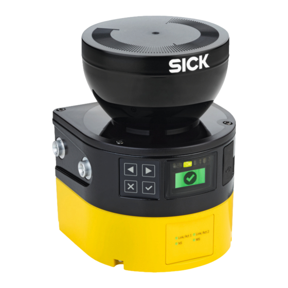
SICK microScan3 EtherNet/IP Operating Instructions Manual (224 pages)
Safety laser scanners
Brand:
SICK
| Category:
Scanner
| Size: 18 MB
Table of Contents
Section 1
3
Table of Contents
3
Target Groups of These Operating Instructions
8
Further Information
8
About this Document
8
Scope
8
Function of this Document
8
Symbols and Document Conventions
9
Safety Information
10
General Safety Notes
10
Intended Use
11
Inappropriate Use
11
Cybersecurity
12
Requirements for the Qualification of Personnel
12
Device Overview
13
Product Description
13
Product Identification Via the SICK Product ID
13
Setup and Function
14
Product Characteristics
15
Variants
15
Connections
16
System Plug
16
Field Types
16
Field Set
20
Monitoring Case
21
Simultaneous Monitoring
22
Example Applications
22
Operator of the Machine
25
Project Planning
25
Manufacturer of the Machine
25
Assembly
26
Protection from Influences
27
Preventing Unprotected Areas
28
Response Time of the Safety Laser Scanner
30
Reference Contour Monitoring
30
Monitoring Case Switching Time
32
Hazardous Area Protection
34
Hazardous Point Protection
41
Access Protection
44
Mobile Hazardous Area Protection
47
Mobile Protection in Narrow Aisles
52
Integration in the Electrical Control System
60
Electromagnetic Compatibility
61
Voltage Supply
62
USB Connection
62
Control Inputs
62
Ethernet/Ip
63
Restart Interlock
63
Integration into the Network
67
Network Topology
67
Network Services and Ports
67
Integration of the Safety Laser Scanner into the Network
68
Configuring Control
69
Available Data
71
Assemblies
72
Testing Plan
74
Planning the Thorough Check During Commissioning and in Certain Situations
74
Planning the Regular Thorough Check
75
Notes on the Tests
76
Mounting
80
Safety
80
Unpacking
80
Mounting Procedure
81
Changing Position of the System Plug
82
Direct Mounting
84
Connection Overview
85
Safety
85
Electrical Installation
85
Microscan3 - Ethernet/Ip
86
Pin Assignment
86
Voltage Supply (XD1)
86
Alternative FE Connection
86
Network for Ethernet/Ip - CIP Safety, Data Output, Configuration, and Diagnostics (XF1, XF2)
87
Configuration
88
Delivery State
88
Safety Designer Configuration Software
88
Installing Safety Designer
88
Projects
88
User Interface
89
User Groups
89
Configuration
91
Settings
91
Networking
93
Overview
94
Functional Scope
95
Hardware Overview
96
Network Settings
97
Ethernet/Ip
97
Time Synchronization
98
Reading Configuration
98
Identification
99
Protocol Settings
100
Ethernet/Ip
100
Application
101
Monitoring Plane
102
Parameters for the Monitoring Plane
102
Reference Contour Field
107
Fields
108
Using the Field Editor
109
Creating Field Set Templates
112
Importing and Exporting Field Sets and Fields
113
Background Image
113
Settings for the Field Editor
114
Editing Fields Using Coordinates
115
Drawing in Points that Cannot be Monitored
117
Defining Global Geometry
118
Enable Propose Field
118
Inputs and Outputs
120
Monitoring Cases
122
Settings for Monitoring Case Tables
122
Several Monitoring Case Tables
124
Settings for Monitoring Cases
124
Input Condition
124
Cut-Off Paths
125
Assigning Field Sets
125
Assigning a Defined Cut-Off Behavior
126
Importing and Exporting Monitoring Case Tables
126
Simulation
128
Data Output
129
Transfer
130
Starting and Stopping Safety Function
131
Ethernet/Ip Overview
132
Reports
133
Service
134
Device Restart
134
Ethernet/Ip
134
Factory Settings
134
Managing Passwords
135
Access Management
136
Optics Cover Calibration
137
Compare Configuration
138
Commissioning
139
Safety
139
Alignment
139
Switching on
140
Check During Commissioning and Modifications
141
Operation
142
Safety
142
Regular Thorough Check
142
Status Indicators
142
Status Leds
142
Network Leds
143
Status Indicator with the Display
145
Maintenance
148
Safety
148
Regular Cleaning
148
Replacing the Optics Cover
149
Replacing the Safety Laser Scanner
151
Replacing the Safety Laser Scanner Without System Plug
152
Replacing the Safety Laser Scanner Completely
153
Replacing the System Plug
153
Regular Thorough Check
154
Troubleshooting
155
Safety
155
Detailed Diagnostics Using the Display
155
Error Indication on the Display
157
Diagnostics Using Safety Designer
159
Data Recorder
160
Event History
161
Message History
163
Status Inputs and Outputs
164
Diagnostics Using the Control
164
Decommissioning
165
Disposal
165
Technical Data
166
Variant Overview
166
Version Numbers and Functional Scope
166
Data Sheet
171
Microscan3 - Ethernet/Ip
171
Response Times
176
Sensing Range
177
Protective Field Range (Devices with a Max. Protective Field Range of 4.0 M)
177
Protective Field Range (Devices with a Max. Protective Field Range of 5.5 M)
177
Protective Field Range (Devices with a Max. Protective Field Range of 9.0 M)
177
Scan Plane
181
Light Spot Size
182
Scan Plane
182
Measurement Data Details
183
Measurement Data
183
Data Exchange in the Network
184
Standard Objects (Open Objects)
184
Manufacturer-Specific Objects (Vendor-Specific Objects)
189
Assemblies
193
Input of the Device (Output of the Control)
193
Output of the Device (Input of the Control)
196
Assembly 100
199
Assembly 103
199
Assembly 105
200
Assembly 113
201
Assembly 110
201
Assembly 120
202
Dimensional Drawings
203
Ordering Information
204
Scope of Delivery
204
Ordering Information
205
Ordering Information for Safety Laser Scanner with System Plug
205
Spare Parts
206
Safety Laser Scanner Without System Plug
206
System Plug
206
Additional Spare Parts
207
Testing Equipment
208
Reference Target
208
Additional Accessories
208
Accessories for Collision Protection
208
Accessories
208
Glossary
209
Annex
213
Conformities and Certificates
213
EU Declaration of Conformity
213
UK Declaration of Conformity
213
Note on Standards
213
Checklist for Initial Commissioning and Commissioning
215
Mounting Methods for Protection from Interference from Systems in Close Proximity
216
List of Figures
219
List of Tables
222
Section 2
223
Advertisement
SICK microScan3 EtherNet/IP Operating Instructions Manual (212 pages)
Safety laser scanner
Brand:
SICK
| Category:
Scanner
| Size: 17 MB
Table of Contents
Section 1
3
Table of Contents
3
1 About this Document
8
Function of this Document
8
Scope
8
Target Groups of These Operating Instructions
8
Further Information
8
Symbols and Document Conventions
9
2 Safety Information
10
General Safety Notes
10
Intended Use
11
Inappropriate Use
11
Requirements for Personnel Qualifications
11
3 Product Description
13
Setup and Function
13
Product Characteristics
15
Device Overview
15
Variants
16
Status Indicators
16
Connections
17
System Plug
17
Field Types
17
Field Set
20
Monitoring Case
21
Simultaneous Monitoring
22
Example Applications
22
4 Project Planning
25
Manufacturer of the Machine
25
Operator of the Machine
25
Assembly
25
Protection from Influences
27
Preventing Unprotected Areas
28
Response Time of the Safety Laser Scanner
30
Reference Contour Monitoring
30
Monitoring Case Switching Time
32
Hazardous Area Protection
34
Hazardous Point Protection
41
Access Protection
44
Mobile Hazardous Area Protection
46
Integrating the Equipment into the Electrical Control
52
Voltage Supply
53
USB Connection
53
Control Inputs
54
Ethernet/Ip
55
Restart Interlock
55
Integration into the Network of the Control
58
Network Topology
58
Integration of the Safety Laser Scanner into the Network
58
Configuring Control
59
Available Data
62
Assemblies
63
Testing Plan
65
Minimum Requirements for the Regular Thorough Check
65
Recommendations for Further Thorough Checks
65
Carrying out Thorough Checks
66
5 Mounting
69
Safety
69
Unpacking
69
Mounting Procedure
69
Changing Position of the System Plug
71
Direct Mounting
73
Mounting Using Mounting Kit 1
74
Mounting Using Mounting Kit 2
74
6 Electrical Installation
77
Safety
77
Connection Overview
77
Microscan3 - Ethernet/Ip
78
Pin Assignment
78
Voltage Supply (XD1)
78
Alternative FE Connection
78
Ethernet for Ethernet/Ip - CIP Safety, Data Output, Configuration, and Diagnostics (XF1, XF2)
79
7 Configuration
80
General Requirements
80
Delivery State
80
Safety Designer
80
Installation Assistant
80
Projects
80
User Interface
81
User Groups
81
Settings
82
Configuration
83
Overview
85
Functional Scope
86
Addressing
88
Reading Configuration
89
Identification
90
Application
92
Monitoring Plane
93
Parameters for the Monitoring Plane
93
Parameters for the Safety Laser Scanner
96
Reference Contour Field
97
Fields
98
Using the Field Editor
99
Creating Field Set Templates
102
Importing and Exporting Field Sets and Fields
103
Background Image
103
Settings for the Field Editor
104
Editing Fields Using Coordinates
105
Drawing in Points that Cannot be Monitored
106
Enable Propose Field
108
Inputs and Outputs
109
Monitoring Cases
111
Settings for Monitoring Case Tables
111
Settings for Monitoring Cases
113
Input Conditions
113
Cut-Off Paths
113
Assigning Field Sets
113
Simulation
115
Data Output
116
Transfer
117
Starting and Stopping Safety Function
118
Ethernet/Ip Overview
119
Reports
120
Service
120
Device Restart
121
Ethernet/Ip
121
Factory Settings
121
Managing Passwords
121
Optics Cover Calibration
122
8 Commissioning
123
Safety
123
Alignment
123
Switching on
124
Thorough Check
125
9 Operation
127
Safety
127
Regular Thorough Check
127
Leds
127
Buttons and Display
128
10 Maintenance
134
Safety
134
Regular Cleaning
134
Replacing the Optics Cover
135
Replacing the Safety Laser Scanner
137
Replacing the Safety Laser Scanner Without System Plug
138
Completely Replacing the Safety Laser Scanner
139
Replacing the System Plug
139
Regular Thorough Check
140
11 Troubleshooting
141
Safety
141
Diagnostic Leds
141
Status Leds
141
Network Light Emitting Diodes
142
Diagnostics Using the Display
144
Status Display
144
Detailed Diagnostics
146
Fault Display
148
Diagnostics Using Safety Designer
150
Data Recorder
151
Event History
152
Message History
154
Inputs and Outputs
154
Diagnostics Using the Control
155
12 Decommissioning
156
Disposal
156
13 Technical Data
157
Variant Overview
157
Version Numbers and Functional Scope
157
Data Sheet
159
Microscan3 - Ethernet/Ip
159
Response Times
164
Sensing Range
165
Data Exchange in the Network
169
Standard Objects (Open Objects)
169
Manufacturer-Specific Objects (Vendor-Specific Objects)
175
Assemblies
179
Assembly 103
183
Assembly 110
183
Assembly 113
184
Dimensional Drawings
185
Assembly 120
185
14 Ordering Information
187
Scope of Delivery
187
Microscan3 Core - Ethernet/Ip™ Ordering Information
187
Microscan3 Pro - Ethernet/Ip™ Ordering Information
187
15 Spare Parts
188
Safety Laser Scanner Without System Plug
188
System Plug
188
Additional Spare Parts
188
16 Accessories
189
Brackets
189
Brackets Ordering Information
189
Connection Technology
191
Ordering Information for Connecting Cable, M12, 4-Pin, A-Coding
191
Ethernet Cable, M12, 4-Pin, D-Coding Ordering Information
192
Ethernet Cable, M12, 4-Pin, D-Coding on RJ45 Ordering Information
192
Ordering Information, USB Cable
192
Alignment Aid
193
Cleaning Agent
193
Test Rods
193
Additional Accessories
193
Ordering Information for Power Supply
193
Connectivity Ordering Information
193
Alignment Aid Ordering Information
193
Cleaning Agent Ordering Information
193
Ordering Information, Test Rods
193
Tools
193
17 Glossary
194
18 Annex
198
Compliance with EU Directives
198
Note on Specified Standards
199
Checklist for Initial Commissioning and Commissioning
200
Mounting Methods for Protection from Interference from Systems in Close Proximity
201
19 List of Figures
204
20 List of Tables
207
Section 2
208
Advertisement
Related Products
SICK microScan3 - EFI-pro
SICK microScan3-EtherNet/IP
SICK microScan3-EFI-pro
SICK microScan3-PROFINET (M12)
SICK microScan3 Core I/O
SICK microScan3 - PROFINET
SICK microScan3 Core I/O AIDA
SICK microScan3 Pro I/O
SICK microScan3-EtherCAT
SICK microScan3-PROFINET
SICK Categories
Accessories
Security Sensors
Measuring Instruments
Scanner
Barcode Reader
More SICK Manuals
Login
Sign In
OR
Sign in with Facebook
Sign in with Google
Upload manual
Upload from disk
Upload from URL