Sign In
Upload
Manuals
Brands
Seagate Manuals
Storage
Exos 5U84 Series
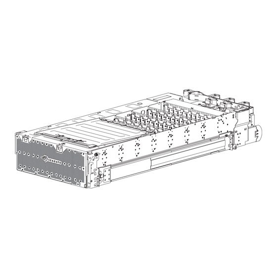
Seagate Exos 5U84 Series Enclosure Manuals
Manuals and User Guides for Seagate Exos 5U84 Series Enclosure. We have
4
Seagate Exos 5U84 Series Enclosure manuals available for free PDF download: Hardware Installation And Maintenance Manual, Manual, Getting Started
Seagate Exos 5U84 Series Hardware Installation And Maintenance Manual (91 pages)
Brand:
Seagate
| Category:
Storage
| Size: 20 MB
Table of Contents
Table of Contents
3
Introduction
8
Intended Audience
8
Knowledge Prerequisites
8
Product Documentation and Support
8
Safety Guidelines
8
System Overview
9
Storage Enclosure Components
9
Storage Enclosure Chassis
9
Storage Enclosure Modules
10
Figure 1 Storage Enclosure with Rails
10
Storage Enclosure Pcbas
11
Figure 2 Customer-Replaceable Frus, Top View
11
Optional Components
12
Figure 3 Pcbas Cutaway with Callouts
12
Initial Installation
13
Complete Installation Prerequisites
13
Installation Checklist
14
Table 1 Installation Checklist Tasks
14
Unpack and Prepare the Storage Enclosure
15
Figure 4 Default Belt Straps Already Around the Storage Enclosure
16
Figure 5 Optional Lift Handles Attached to the Storage Enclosure
16
Install the Rackmount Rail Kit
17
Figure 6 Left and Right Lift Handles
17
Separate the Inner Rails from the Outer and MID Rails
18
Figure 7 Details of Left Rail Assembly with Facing Inner Sides
19
Figure 8 Extension of Left Inner Rail Beyond MID Rail
20
Figure 9 Location of Inner Rail Safety Lock
20
Adjust the Outer Rails to the Rack Cabinet
21
Figure 10 Location of MID Rail Release Switch Lever
21
Figure 11 Distance Measurement of Rack Inside Post-To-Post Depth
22
Figure 12 Default Location of Outer Rail Adjustment Setscrews
22
Figure 13 Measurement of Rail from Rear to Front Mount Bracket
23
Figure 14 Sample Adjusted Distance for Outer Rail Setscrews
23
Install the Outer Rails in the Rack Cabinet
24
Figure 15 Alignment of CMA B Bracket to Rear Outer Rail Bracket Holes Alignment and Attachment
24
Figure 16 Attach the Rear of the Outer Right Rail Assembly
25
Figure 17 Right Front Post Detail of the Inserted Outer Right Rail Assembly
26
Attach the Inner Rails to the Storage Enclosure
27
Figure 18 Location for Cage Nut Near Top of Allocated 4U Space
27
Figure 19 Left and Right Inner Rail Edge Details
28
Figure 20 Left Inner Rail Alignment to Storage Enclosure Chassis
28
Figure 21 Lock of Rail against T-Pins, Alignment of Screw Holes to Chassis Sidewall
28
Install the Storage Enclosure
29
Mount the Storage Enclosure into the Rack Cabinet
29
Figure 22 Attachment of the CMA a Bracket
29
Figure 23 Alignment Detail of Inner Rails with MID and Outer Rails
30
Figure 24 Engagement of Either Leaf Spring Latch, MID Rail Extension to Fully Forward and Locked Position
31
Install the CMA and Crossbar
32
Figure 25 Location for Release of both Safety Lock Latches
32
Figure 26 Attachment of the CMA Assembly to the CMA a Bracket on the Chassis
33
Figure 27 Insertion of CMA Assembly Onto Outer Rail CMA Bracket
34
Figure 28 Proper Installation of the CMA Assembly
34
Figure 29 Direction to Tighten Crossbar Thumbscrews
35
Figure 30 Location for Insertion of Rack Ear Transport Screws
35
Install Drive Carriers in the Storage Enclosure
36
Figure 31 Location for Insertion of Crossbar Transport Screws
36
Figure 32 Front Half of Unpopulated Main Bay
37
Figure 33 Orient Drive Carrier Handle to Rear
37
Figure 34 Required Installation of First Complete Row of Drive Carriers
38
Figure 35 Rear Half of Unpopulated Main Bay
38
Test Power Source for Electrical Earth Connection
39
Route Power Cords and Data Cables
39
Figure 36 Auxiliary Bay Latch
39
Route Power Cords from the Power Supply Units
40
Figure 37 Location of Cable Capture Clip Release Screw
41
Figure 38 Power Cord Routing Around Fans and up to Cable Capture Clip
41
Figure 39 Final Power Cord Routing
41
Route Data Cables from the Controller Module
42
Figure 40 Open Cable Capture Arms on Chassis
42
Figure 41 Proper Order of Data Cables
43
Figure 42 Route for Sample Data Cables on Either Side of the CMA Cable Capture Arm
43
Route and Connect Power Cords and Data Cables
44
Figure 43 Sample HBA Data and Management Connections
44
Figure 44 Close All CMA Bracket Clips
45
Operation
46
Apply Power to the Storage Enclosure
46
Set the Unit Identification Number
47
Interpret System Leds
47
Figure 45 Connection of Power Cable Plugs to Redundant Pdus
47
Interpret Front Panel Leds
48
Figure 46 Interpretation of Front Panel Leds
48
Table 2 Fault LED Prioritization
48
Interpret Controller Module Leds
49
Figure 47 Controller Module Leds
49
Table 3 Host Port Link LED Status Types
49
Storage Enclosure Management
50
Command-Line Interface Usage
50
Table 4 Methods of Access to Controller Module
50
Table 5 Interface Options
50
Figure 48 Ports on Sample Controller Module
51
Table 6 Supported Terminal Emulator Applications
51
Table 7 Sample Linux Minicom Serial Port Parameter Settings
52
Table 8 Terminal Emulator Port Connection Settings
53
Table 9 Factory Default Network Port IP Addresses
54
Storage Management Console Usage
55
Table 10 Supported Browsers
55
Hardware Installation and Configuration Issues
57
Address Initial Start-Up Issues
57
Interpret FRU Fault Condition Leds
58
Drive Module Fault LED
58
SAS Expander Module Fault LED
58
Figure 49 Interpretation of Drive Fault LED on Top Panel
58
Figure 50 Interpretation of SAS Expander Module Fault Leds, Component Side
58
Controller Fan Module Fault LED
59
System Fan Module Fault LED
59
Figure 51 Interpretation of Controller Fan Module Fault LED, Rotated Orientation
59
Power Supply Unit Status LED
60
Figure 52 Interpretation of System Fan Module Fault LED
60
Figure 53 Interpretation of Power Supply Unit Fault LED
60
Controller Module Fault Leds
61
Identify Fault Conditions
61
Figure 54 Interpretation of Controller Module Fault Leds
61
Isolate Hardware and Connectivity Faults
62
Table 11 Non-Fault Conditions
62
Isolate System Application Faults
63
Table 12 Status of Drive Module or Array, Based on Front Panel Fault-Application LED
63
Take Corrective Action
64
Table 13 Status of CM , Based on the Green Cache LED State and Reboot
64
Table 14 Corrective Action for Fault Conditions
64
In-Service Field Maintenance
67
Table 15 Time Limits for FRU Replacement
67
Replace a Drive Module in Its Carrier
68
Figure 55 Interpretation of Drive Fault LED on Top Panel
69
Figure 56 Removal of Drive Carrier from the Main Bay, Other Drive Carriers Removed for Clarity
70
Replace a SAS Expander Module
71
Figure 57 Orientation of Drive Carrier Handle
71
Figure 58 Interpretation of SAS Expander Module Leds, Component Side
72
Replace a Controller Fan Module
73
Figure 59 Removal of a SAS Expander Module
73
Figure 60 Interpretation of Controller Fan Module Fault LED, Rotated Orientation
74
Replace a System Fan Module
75
Figure 61 Removal of a Controller Fan
75
Figure 62 Interpretation of System Fan Module Fault LED
76
Replace a Power Supply Unit
77
Figure 63 Removal of a System Fan, Crossbar Not Shown for Clarity
77
Figure 64 Interpretation of Power Supply Unit Fault LED
78
Figure 65 Removal of the PSU Without Power, Crossbar Not Shown for Clarity
79
Figure 66 PSU Fully Removed, Crossbar Not Shown for Clarity
79
Replace a Controller Module
80
Figure 67 Controller Module Leds to Examine for Fault Conditions
80
Replace a Main Bay Cover
82
Figure 68 Release of the Controller Module Latch Handle
82
Figure 69 Location of Main Bay Cover's Rear Latch
83
Figure 70 Rear Half of an Unpopulated Main Bay, Unpopulated for Clarity
83
Figure 71 Rear Half of an Unpopulated Main Bay, Unpopulated for Clarity
84
Replace an Auxiliary Bay Cover
85
Figure 72 Location of Auxiliary Bay Cover's Latch
85
A Technical Specifications
87
Table 16 Storage Enclosure Dimensions
87
Table 17 Storage Enclosure FRU Weights¹
87
Table 18 Storage Enclosure Total Weights
87
Table 19 Environmental Specifications
87
Table 20 Power Specifications
88
B Standards and Regulations
89
International Standards
89
Potential for Radio Frequency Interference
89
WEEE Recycling
89
Table 21 Safety Compliance
89
Index
90
Advertisement
Seagate Exos 5U84 Series Hardware Installation And Maintenance Manual (99 pages)
Brand:
Seagate
| Category:
Storage
| Size: 13 MB
Table of Contents
Table of Contents
3
Introduction
8
Knowledge Prerequisites
8
Product Documentation and Support
8
Intended Audience
9
System Overview
10
Expansion Enclosure Components
10
Table 1 Expansion Enclosure Variations
10
Expansion Enclosure Chassis
11
2U Enclosure Components
11
Figure 1 2U12 and 2U24 Front Panel Area
12
5U Enclosure Components
13
Figure 2 2U12 and 2U24 Rear Panel Area
13
Figure 3 5U84 Front Panel Area
14
Figure 4 5U84 Rear Panel Area
15
Optional Components
16
Figure 5 Profile and Top Views of Fully Populated 5U84 Drawers
16
Initial Install Preparations
18
Installation Checklist
18
Table 2 Installation Checklist Tasks
18
Complete Installation Prerequisites
19
Installation of 2U Enclosures
21
Unpack and Prepare the 2U Enclosure
21
Figure 6 2U12 and 2U24 Expansion Enclosure Packaging, Shown Without Plastic for Clarity
21
Install the 2U Rackmount Rail Kit
22
Figure 7 2U Enclosure Outer Rail Components
23
Figure 8 Attachment of Front Mount Bracket to Front Rack Cabinet Posts
24
Figure 9 Adjustment of Rail Length to Fit Rack Cabinet
24
Mount the 2U Enclosure into the Rack Cabinet
25
Figure 10 Attachment of Rear Mount Bracket to Rear Rack Cabinet Posts
25
Figure 11 Alignment between 2U Chassis and Rails (Removed Rear Components for Clarity)
26
Populate the 2U Enclosure
27
Figure 12 Installation of 2U Rear Screw to Secure Chassis to Rail
27
Test Enclosure Electrical Earth Connection
28
Route 2U Enclosure Data Cables and Power Cords
28
Route 2U Enclosure Host Cables and Expansion Data Cables
29
Route 2U Enclosure Power Cords
30
Figure 13 Sample Reverse Cabling Method Among the Host System and 2U Expansion Modules
30
Figure 14 Sample Invalid Loop (in Red) Among the Host System and 2U Expansion Modules
30
Figure 15 2U Power Cord Routing to Independent Power Distribution Units
31
Installation of 5U Enclosures
32
Unpack and Prepare the 5U Enclosure
32
Figure 16 Default Belt Straps Already Around the 5U Expansion Enclosure
32
Install the 5U Rackmount Rail Kit
33
Figure 17 5U Left and Right Rail Components
35
Figure 18 Insertion of 5U Front Mount Bracket Screw
36
Figure 19 Insertion of 5U Rear Mount Bracket Screws
36
Mount the 5U Enclosure into the Rack Cabinet
37
Figure 20 Alignment between 5U Chassis and Rails, Minus Rear Components for Clarity
38
Figure 21 Secure Chassis Operator's Panel to Rack Posts
39
Figure 22 5U Rear Chassis Connection to Outer Rails, Detail, Minus Rear Components for Clarity
39
Access a Drawer
40
Figure 23 Safety Lock to Release Left Drawer Slide Rail (Lower Drawer Used for Relational Clarity)
40
Populate the 5U Enclosure
41
Figure 24 Carrier Latch Features
41
Figure 25 Release Latch Open and Unlocked
41
Figure 26 Release Latch Properly Locked
41
Test Enclosure Electrical Earth Connection
42
Route 5U Enclosure Data Cables and Power Cords
42
Route 5U Enclosure Host Cables and Expansion Data Cables
43
Route 5U Enclosure Power Cords
44
Figure 27 Sample Reverse Cabling Method Among the 5U Host System and Expansion Modules
44
Figure 28 Sample Invalid Loop (in Red) Among the 5U Host System and Expansion Modules
44
Figure 29 5U Power Cord Routing to Independent Power Distribution Units
45
Operation of 2U Enclosures
46
Apply Power to the 2U Enclosure
46
Remove Power from the 2U Enclosure
47
Set the Unit Identification Number
47
Table 3 Fault LED Prioritization
48
Figure 30 2U12 and 2U24 Operator's Panel Leds
49
Figure 31 SAS 12Gb/S Expansion Input/Output Module Leds
50
Table 4 Fault LED Prioritization
53
Figure 32 5U84 Operator's Panel Leds
54
Figure 33 5U84 Drawer LED Panel
55
Figure 34 SAS 12Gb/S Expansion Input/Output Module Leds
56
Figure 35 2U12 and 2U24 Operator's Panel Fault Leds
58
Figure 36 2U12 and 2U24 Fault Leds on Carrier Bezel
59
Figure 37 SAS 12Gb/S Expansion Module Fault Leds
59
Figure 38 Power Cooling Module Fault Leds
60
Figure 39 5U84 Operator's Panel Fault Leds
61
Figure 40 5U84 Drawer Fault Leds on Drawer LED Panel
62
Figure 41 Drive Fault LED on Carrier Bezel
62
Figure 42 SAS 12GB Expansion Module Fault Leds
63
Figure 43 Fan Cooling Module Fault Leds
64
Figure 44 Power Supply Unit Fault Leds
64
Table 5 2U Enclosure Non-Fault Conditions
65
Table 6 5U Enclosure Non-Fault Conditions
66
Table 7 2U Enclosure Corrective Action for Fault Conditions
68
Table 8 5U Enclosure Corrective Action for Fault Conditions
69
Table 9 2U Enclosure Time Limits for FRU Replacement
73
Figure 45 2U12 and 2U24 Fault Leds on Carrier Bezel
74
Figure 46 Removal of 2U12 and 2U24 Drive in Carrier
75
Figure 47 Replacement with Open 2U12 and 2U24 Carrier Handle
76
Figure 48 SAS 12Gb/S Expansion Input/Output Module Leds
77
Figure 49 Input/Output Module Removal, Upper
78
Figure 50 Replacement Input/Output Module
78
Figure 51 Power Cooling Module Removal
80
Figure 52 Replacement Power Cooling Module
80
Table 10 5U Enclosure Time Limits for FRU Replacement
82
Figure 53 Drive Fault LED on Carrier Bezel
83
Figure 54 Operator's Panel
84
Figure 55 Drawer Panel
84
Figure 56 Drawer Release and Access
84
Figure 57 Carrier Latch Features
85
Figure 58 Removal of Drive in Its Carrier
85
Figure 59 Replacement of Drive in Its Carrier
86
Figure 60 Release Latch Open and Unlocked
86
Figure 61 Release Latch Properly Locked
86
Figure 62 Safety Lock to Release Left Drawer Slide Rail of Lower Drawer
87
Figure 63 SAS 8Gb/S Input/Output Module Leds
88
Figure 64 Input/Output Module Removal, Left
89
Figure 65 Replacement Input/Output Module
89
Figure 66 Fan Cooling Module Fault Leds
90
Figure 67 Fan Cooling Module Removal
91
Figure 68 Replacement Fan Cooling Module
91
Figure 69 Power Supply Unit Fault Leds
92
Figure 70 Power Supply Unit Removal
93
Figure 71 Replacement Power Supply Unit
93
Table 11 Expansion Enclosure Dimensions
95
Table 12 Expansion Enclosure FRU Weights
95
Table 13 Environmental Specifications
95
Table 14 Power Specifications
96
Table 15 Standard and Approvals
97
Seagate Exos 5U84 Series Manual (18 pages)
Rackmount
Brand:
Seagate
| Category:
Racks & Stands
| Size: 3 MB
Advertisement
Seagate Exos 5U84 Series Getting Started (2 pages)
Brand:
Seagate
| Category:
Computer Hardware
| Size: 0 MB
Table of Contents
Product Documentation and Support
1
Product Setup
1
Installation Checklist
2
Installation Prerequisites and Safety Guidance
2
Advertisement
Related Products
Seagate Momentus 5400.3
Seagate Medalist 5130
Seagate MEDALIST 545XE
Seagate Momentus 5400 FDE.3 SATA
Seagate MOMENTUS 5400.3 SATA
Seagate Momentus 5400.3 PSD SATA
Seagate Skyhawk Surveillance 512E
Seagate Momentus 54
Seagate Barracuda 50 ST150176LW
Seagate FireCuda 520
Seagate Categories
Storage
Computer Hardware
Network Storage Server
DC Drives
Network Hardware
More Seagate Manuals
Login
Sign In
OR
Sign in with Facebook
Sign in with Google
Upload manual
Upload from disk
Upload from URL