Seagate Exos CORVAULT 5U84 Hardware Installation And Maintenance Manual
Hide thumbs
Also See for Exos CORVAULT 5U84:
- Hardware installation and maintenance manual (99 pages) ,
- Manual (18 pages) ,
- Getting started (2 pages)
Table of Contents
Advertisement
Quick Links
Exos® CORVAULT™ Hardware
Installation and Maintenance Guide
Abstract
This guide describes initial hardware setup for a Seagate Exos CORVAULT enclosure. It also describes removal and
installation of customer-replaceable components. The guide is intended for use by storage system administrators
familiar with servers and computer networks, network administration, storage system administration and
configurations, storage area network management, and relevant protocols.
Part Number: 205070700-00
Revision: A
Published: April 2023
Advertisement
Table of Contents

Related Manuals for Seagate Exos CORVAULT 5U84


Summary of Contents for Seagate Exos CORVAULT 5U84
- Page 1 Installation and Maintenance Guide Abstract This guide describes initial hardware setup for a Seagate Exos CORVAULT enclosure. It also describes removal and installation of customer-replaceable components. The guide is intended for use by storage system administrators familiar with servers and computer networks, network administration, storage system administration and configurations, storage area network management, and relevant protocols.
- Page 2 Seagate Technology LLC or its affiliates. Any use, derivation, disassembly, reverse engineering, dissemination, reproduction, or any attempt to modify, prepare derivative works, reproduce, distribute, disclose copyrighted material of Seagate Technology LLC, for any reason, in any manner, medium, or form, in whole or in part, if not expressly authorized, is...
-
Page 3: Table Of Contents
Contents 1 Introduction Intended audience Knowledge prerequisites Product documentation and support Safety guidelines 2 System overview Storage enclosure components Storage enclosure chassis Storage enclosure modules Storage enclosure PCBAs Optional components 3 Initial installation Complete installation prerequisites Installation checklist Unpack and prepare the storage enclosure Install the rackmount rail kit Separate the inner rails from the outer and mid rails Adjust the outer rails to the rack cabinet... - Page 4 Storage Management Console usage 5 Hardware installation and configuration issues Address initial start-up issues Interpret FRU fault condition LEDs Drive module fault LED SAS expander module fault LED Controller fan module fault LED System fan module fault LED Power supply unit status LED Controller module fault LEDs Identify fault conditions Isolate hardware and connectivity faults...
- Page 5 Figures Figure 1 Storage enclosure with rails Figure 2 Customer-replaceable FRUs, top view Figure 3 PCBAs cutaway with callouts Figure 4 Default belt straps already around the storage enclosure Figure 5 Optional lift handles attached to the storage enclosure Figure 6 Left and right lift handles Figure 7 Details of left rail assembly with facing inner sides Figure 8 Extension of left inner rail beyond mid rail Figure 9 Location of inner rail safety lock...
- Page 6 Figure 39 Final power cord routing Figure 40 Open cable capture arms on chassis Figure 41 Proper order of data cables Figure 42 Route for sample data cables on either side of the CMA cable capture arm Figure 43 Sample HBA data and management connections Figure 44 Close all CMA bracket clips Figure 45 Connection of power cable plugs to redundant PDUs Figure 46 Interpretation of front panel LEDs...
- Page 7 Tables Table 1 Installation checklist tasks Table 2 Fault LED prioritization Table 3 Host port link LED status types Table 4 Methods of access to controller module Table 5 Interface options Table 6 Supported terminal emulator applications Table 7 Sample Linux Minicom serial port parameter settings Table 8 Terminal emulator port connection settings Table 9 Factory default network port IP addresses Table 10 Supported browsers...
-
Page 8: Introduction
Storage area network (SAN) management Serial Attached SCSI (SAS) protocol Ethernet protocol RAID technology Product documentation and support To obtain documentation, videos, and product information, visit www.seagate.com/support. Content description Document Seagate QR codes Enhancements, known issues, and updates Release Notes... -
Page 9: System Overview
2 System overview The Exos CORVAULT storage enclosure mounts to a rack cabinet, occupying four EIA rack space units (4U) and contains up to 106 hot-swappable drive modules. CAUTION Make sure you are not connected to power at any time during installation procedures. CAUTION Only operate the storage enclosure in a dust-free environment to meet temperature control and airflow requirements. -
Page 10: Storage Enclosure Modules
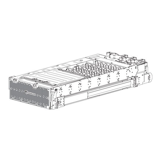
Figure 1 Storage enclosure with rails Storage enclosure modules The storage enclosure contains a number of field-replaceable units (FRUs). Modules or components that require Seagate- authorized warranty and repair personnel to replace them are not identified. CAUTION If you partially populate the storage enclosure with drive modules, you must populate from front to back, filling an entire lateral bay before populating the next bay. -
Page 11: Storage Enclosure Pcbas
The storage enclosure provides separate access to two bays: the main bay and the auxiliary bay. The PCBAs identified in this section are assemblies that require replacement by Seagate-authorized warranty and repair personnel, other than the SAS expander modules and the controller PCB that is part of the controller module. -
Page 12: Optional Components
Item Description Function Power midplane (1) Distributes power from the power supply units to each fan module and all 24-HDD baseplanes, sends signals to the controller module, and provides high-speed busbar harness connection for both drive module and controller channels SAS riser sideplane (4) Passively balances drive module paths between both SAS expander modules, one per24-HDD baseplane... -
Page 13: Initial Installation
3 Initial installation Each storage or expansion enclosure installation requires the same amount of preparation to successfully mount it into your 1.2m industry-standard rack cabinet. WARNING! Heed all warnings and cautions on labeling and throughout this guide to reduce risk of personal injury or damage to equipment. -
Page 14: Installation Checklist
NOTE Allocate and maintain a 1.7m (5.58 foot) safe distance to mount or remove a storage enclosure into a rack. 5. Secure sufficient staff to assist with the installation. Minimum staff: a. One qualified service technician for the complete installation procedure b. -
Page 15: Unpack And Prepare The Storage Enclosure
CAUTION The storage enclosure ships in a partially-populated state. All PCBAs and FRUs ship in the storage enclosure, but the disk drives do not. It is very heavy, so handle with care and adhere to Seagate recommendations. There are two primary packing configurations: a three-piece or a regular slotted container. Neither configuration includes the drive modules, which ship separately, based on system configuration: Single drive modules, 10-packs, or 24-packs. -
Page 16: Figure 4 Default Belt Straps Already Around The Storage Enclosure
6. Prepare to remove the storage enclosure from the container, using one of two options, depending on the shipment: a. Default provided belt straps: Locate three to four people to assist in moving the storage enclosure onto the mechanical lift, using an appropriate safe lifting technique and following the steps for default belt straps. Figure 4 Default belt straps already around the storage enclosure b. -
Page 17: Install The Rackmount Rail Kit
8. For the optional lift handle procedure, perform the following actions: a. Skip the default belt strap step. b. Separate the left lift handles from the right lift handles. The left ones have a locking edge mid-point on the bracket, while the right ones have a locking edge toward the bottom of the bracket. -
Page 18: Separate The Inner Rails From The Outer And Mid Rails
CAUTION Observe all the following directives: Always place the rack cabinet on a flat, leveled surface. Do not install enclosure into a rack cabinet until you verify the rack cabinet is level. Follow prescribed leveling procedures from the rack cabinet manufacturer. Never install or remove from the rack cabinet more than one enclosure at a time. -
Page 19: Figure 7 Details Of Left Rail Assembly With Facing Inner Sides
Item Description Item Description Front mount bracket End cap Outer rail Slotted screw holes Ball bearing retainer T-pin keyholes Rear mount bracket Safety lock Mid rail, slides within outer rail Inner rail Figure 7 Details of left rail assembly with facing inner sides To separate the inner rails from the outer and mid rail sub-assemblies: 1. -
Page 20: Figure 8 Extension Of Left Inner Rail Beyond Mid Rail
Figure 8 Extension of left inner rail beyond mid rail 5. Turn the left rail assembly over, then press the safety lock to disengage the inner rail. Figure 9 Location of inner rail safety lock 6. Slide out the left inner rail until it separates from the outer rail subassembly, setting it aside. 7. -
Page 21: Adjust The Outer Rails To The Rack Cabinet
Figure 10 Location of mid rail release switch lever 8. Rotate the mid rail release switch lever to release it, then slide the left mid rail back until fully retracted onto the outer rail. 9. Set aside the left outer rail subassembly near the left inner rail. 10. -
Page 22: Figure 11 Distance Measurement Of Rack Inside Post-To-Post Depth
To adjust the outer rails to the rack cabinet: 1. Facing the left side of the rack cabinet, measure the distance of the post-to-post depth between the inner side of the rear and front rack posts. Figure 11 Distance measurement of rack inside post-to-post depth 2. -
Page 23: Figure 13 Measurement Of Rail From Rear To Front Mount Bracket
5. Measure the rail distance from the inside of the front mount bracket to inside of the back mount bracket to determine if it matches the distance between rack posts. Figure 13 Measurement of rail from rear to front mount bracket 6. -
Page 24: Install The Outer Rails In The Rack Cabinet
Figure 15 Alignment of CMA B bracket to rear outer rail bracket holes alignment and attachment 11. Repeat the adjustment process for the right outer rail, using the proper orientation for the rack cabinet and rail. Install the outer rails in the rack cabinet WARNING! If you do not properly install and securely fasten the rack rails according to this procedure, you risk serious personal injury and could damage the storage enclosure. -
Page 25: Figure 16 Attach The Rear Of The Outer Right Rail Assembly
To install the outer rails in the rack cabinet: 1. Verify that you assembled the rack rails according to prior tasks, orienting it with embossed arrows pointing upward. 2. Complete the following actions to insert the right outer rail assembly as shown to attach it to the rear post on the right side of the rack cabinet: a. -
Page 26: Figure 17 Right Front Post Detail Of The Inserted Outer Right Rail Assembly
Figure 17 Right front post detail of the inserted outer right rail assembly g. Secure the front mount bracket by tightening the screw with a #2 Phillips-head screwdriver to a torque of 35 lbf-in (3.95 N-m). 4. Complete the following actions to insert cage nuts in the right front rack post: a. -
Page 27: Attach The Inner Rails To The Storage Enclosure
Figure 18 Location for cage nut near top of allocated 4U space 5. Repeat the entire procedure for the left outer rail assembly and the perform a fit check to validate each rail's correct length and location within the rack cabinet. Attach the inner rails to the storage enclosure You must correctly attach the inner rails to the storage enclosure to bear the weight of its contents. -
Page 28: Figure 19 Left And Right Inner Rail Edge Details
To attach the inner rails to the storage enclosure: 1. Examine the inner rails, locating the smooth inner edge of the rail, the flanged outer edge, and the rear top notch. Figure 19 Left and right inner rail edge details 2. -
Page 29: Install The Storage Enclosure
6. Repeat the process for the right inner rail, using the proper orientation. 7. Locate the CMA A bracket in the CMA shipping box, then orient it so you can see the part number etched on it. 8. Facing the rear of the storage enclosure, locate the two holes on the right side of the chassis, above the CMA shelf. 9. -
Page 30: Figure 23 Alignment Detail Of Inner Rails With Mid And Outer Rails
Make your approach with the mechanical lift level, straight, and parallel to the rack cabinet. Any skew, warp, or tilt prevents the inner rails attached to the storage enclosure from properly engaging the outer rails in the rack cabinet. Required equipment Retractable tape measure Mechanical lift Storage enclosure with attached inner rails... -
Page 31: Figure 24 Engagement Of Either Leaf Spring Latch, Mid Rail Extension To Fully Forward And Locked Position
IMPORTANT Retention against the inner leaf spring is essential for proper rail sequencing and full engagement of the mid rail on the inner rail. NOTE The location of the leaf spring at the rail's top or bottom depends on if it is a left or right rail. Figure 24 Engagement of either leaf spring latch, mid rail extension to fully forward and locked position c. -
Page 32: Install The Cma And Crossbar
6. Complete the following actions to begin insertion of the storage enclosure into the rack cabinet: a. Facing the front of the enclosure, carefully exert even pressure on both sides of the storage enclosure front, inserting the storage enclosure until it locks into the service position with an audible click. b. -
Page 33: Figure 26 Attachment Of The Cma Assembly To The Cma A Bracket On The Chassis
Required equipment Identification CMA bracket assembly Crossbar #2 Phillips-head screwdriver, 12-in length (Optional) Panhead screw, M5 0.8x4mm length (Optional) Truss head screws, 10-32x3/4 in length To install the CMA and crossbar: 1. Facing the rear of the rack cabinet, grasp the CMA assembly so that arrows by embossed letters point upward and are visible to you, then fully extend the CMA assembly with the front end in your right hand. -
Page 34: Figure 27 Insertion Of Cma Assembly Onto Outer Rail Cma Bracket
4. Route the portion of the CMA assembly in your left hand inward until it clips to the outer rail CMA bracket. Figure 27 Insertion of CMA assembly onto outer rail CMA bracket 5. Complete the following actions to verify the CMA assembly installation: Figure 28 Proper installation of the CMA assembly a. -
Page 35: Figure 29 Direction To Tighten Crossbar Thumbscrews
Figure 29 Direction to tighten crossbar thumbscrews 8. (Optional) For non-operating transport of the rack cabinet, complete the following steps: a. Return to the front of the rack cabinet. b. Lower the pull handle, and then insert and tighten 2 Truss-head screws per side in the available screw holes on the rack ear to a torque of 35 lbf-in (3.95 N-m). -
Page 36: Install Drive Carriers In The Storage Enclosure
TIP Use the QR code on the included Getting Started sheet to access related storage enclosure documentation online. Install drive carriers in the storage enclosure Seagate provides drive carriers to protect each drive module and connect each drive module to the baseplane after vertical insertion into a slot. -
Page 37: Figure 32 Front Half Of Unpopulated Main Bay
Figure 32 Front half of unpopulated main bay 4. Select the first drive carrier from the static-protected area you used when unpacking the storage enclosure. 5. Go to the right side of the open storage enclosure, so that the auxiliary bay is to the top of your workspace. 6. -
Page 38: Figure 34 Required Installation Of First Complete Row Of Drive Carriers
Figure 34 Required installation of first complete row of drive carriers 9. Firmly press the drive carrier into the mating connector on the baseplane. 10. Close and press down on the drive carrier handle until you engage the locking mechanism. 11. -
Page 39: Test Power Source For Electrical Earth Connection
f. In SAS configurations, press the front latch of the auxiliary bay cover, remove the cover, and set it aside to access the auxiliary bay. Figure 36 Auxiliary bay latch g. Continue insertion of the remaining drive modules provided as part of your configuration to complete population of the auxiliary bay using the same progression from front to back. -
Page 40: Route Power Cords From The Power Supply Units
IMPORTANT Use only Seagate or OEM-qualifiedHD mini-SAS (SFF-8644) x4 data cables that are at least 3m (9.83 feet) in length and do not exceed the length specified in the Compatibility Interop Matrix for your configuration to connect to the SAS ports on each controller module. -
Page 41: Figure 37 Location Of Cable Capture Clip Release Screw
Figure 37 Location of cable capture clip release screw 4. Route the outer power cord just inside the outer fan and up to the left clip, allowing a minimum of slack. 5. Route the inner power cord just inside the third fan and up to the right clip, allowing a minimum of slack. Figure 38 Power cord routing around fans and up to cable capture clip 6. -
Page 42: Route Data Cables From The Controller Module
8. Proceed with routing data cables and power cords in the next tasks, leaving the power cord plugs for future connection when you complete all other cabling tasks and are fully ready to test your connections. Route data cables from the controller module The storage enclosure chassis retains cable capture mechanisms for securing data cables to the chassis. -
Page 43: Figure 41 Proper Order Of Data Cables
Figure 41 Proper order of data cables 5. (Optional) Complete the following actions to route an Ethernet cable to each of the controller modules: a. Route the first Ethernet cable, numbered 9, to the Ethernet port on the outer controller module. b. -
Page 44: Route And Connect Power Cords And Data Cables
6. Complete the following actions to route cable groups through the cable capture arm: a. Route the first group of five cables, numbered 1 to 4 and 9, so they lie flat as shown on the base of the open cable capture arm. -
Page 45: Figure 44 Close All Cma Bracket Clips
NOTE The following cable configuration is only a sample configuration and changes, based on individual system requirements. To route and connect power cords and data cables: 1. Route the power cords straight toward and then behind the first L-shaped bracket. 2. -
Page 46: Operation
4 Operation The storage enclosure management interface allows for provisioning, monitoring, and managing the storage enclosure. It uses the storage enclosure processor (SEP) and associated monitoring and control logic, such as the SCSI Enclosure Services (SES) service, to identify, assess, and diagnose storage enclosure hardware systems. CAUTION Never attempt to power on or operate the storage enclosure until it reaches the proper operating temperature and humidity requirements identified in the Environmental Requirements... -
Page 47: Set The Unit Identification Number
with redundant power. IMPORTANT The storage enclosure design requires two redundant power supply units (PSUs). You must plug each power cord into an independent power distribution unit (PDU) that connects to an uninterruptible power system. Figure 45 Connection of power cable plugs to redundant PDUs 2. -
Page 48: Interpret Front Panel Leds
Since an amber fault LED uses fast or slow flashes to cover multiple conditions, here is the priority for simultaneous indications: Table 2 Fault LED prioritization Priority Flash rate Indication Description Top priority Fast flash (1s on, 1s off) Identify Locate the enclosure or module Priority 2 Fault... -
Page 49: Interpret Controller Module Leds
Interpret controller module LEDs There are two redundant controller modules (CMs) that use a series of LEDs to reflect host connectivity status. You can monitor the LEDs from the rear panel to determine system status in combination with the user interface content. In the case of a fault condition, identified in the state column with an asterisk (*), troubleshoot the fault and take the appropriate corrective action. -
Page 50: Storage Enclosure Management
Table 3 Host port link LED status types (continued) LEDs Type Color State Status SAS connected; all four active SAS lanes functioning at same negotiated speed Green Flashing SAS connected; all four active SAS lanes register input or output activity No host link detected SAS connected;... -
Page 51: Figure 48 Ports On Sample Controller Module
OS recognizes the USB device and can connect to a controller module. To install a device driver: 1. Navigate to https://www.seagate.com/support/systems/general-support/ and locate the device driver for download. 2. Download the zip file to the management computer. -
Page 52: Table 7 Sample Linux Minicom Serial Port Parameter Settings
Configure Linux for serial communication If you do not have a terminal emulator, such as Minicom, you must obtain one prior to completion of this task. IMPORTANT While a Linux system may not require installation of a device driver, it might require USB parameters as you load the device driver to enable controller recognition. -
Page 53: Table 8 Terminal Emulator Port Connection Settings
An installed and tested Windows USB device driver to connect to the controller module USB port, by using the native USB serial driver for Windows 10/Server 2016 or higher, or by downloading and installing the Seagate device driver. To configure Windows for serial communication: 1. -
Page 54: Table 9 Factory Default Network Port Ip Addresses
Table 9 Factory default network port IP addresses IP version Controller 0A addresses Controller 0B addresses IP address: 10.0.0.2 IP address: 10.0.0.3 IPv4 IP subnet mask: 255.255.255.0 IP subnet mask: 255.255.255.0 Gateway IP address: 10.0.0.1 Gateway IP address: 10.0.0.1 Autoconfig: Enabled Autoconfig: Enabled... -
Page 55: Storage Management Console Usage
Storage Management Console usage Seagate provides a user-friendly interface that provides the means to configure, monitor, and manage the storage system: the Storage Management Console (SMC). See the Storage Management Guide. Access it through a supported browser, then use it to complete initial configuration of the management host, then monitor and manage the storage enclosure. - Page 56 NOTE By default, your system is loaded with self-signed certificates. You should generate new self-signed certificates on each controller, using the create certificate CLI command. Expect browser warnings about security or privacy concerns related to self-signed or untrusted certificates or invalid certificate authorities. Bypass such warnings if you are confident of a secure connection.
-
Page 57: Hardware Installation And Configuration Issues
IMPORTANT Do not use this section for configured systems already interacting with production data. For the kind of assistance you need in such cases, contact Seagate for technical support. Address initial start-up issues You must successfully complete the installation tasks in the identified sequence. You must use the power cords provided with the system and install interface cables that meet system requirements. -
Page 58: Interpret Fru Fault Condition Leds
Interpret FRU fault condition LEDs Throughout the storage enclosure, amber LEDs indicate a fault condition. Some FRUs are more complex than others, so have more than one fault condition. Those items in the state column with an asterisk (*) indicate a fault condition. Drive module fault LED The drive module uses an amber fault LED to identify various states. -
Page 59: Controller Fan Module Fault Led
Controller fan module fault LED The controller fan module has a single amber fault LED to identify various states. The asterisk (*) indicates a fault condition. Color State Status None No AC power is present or the controller fan module is functioning normally. The controller fan module has a hardware fault. -
Page 60: Power Supply Unit Status Led
Color State Status None No AC power is present or the system fan module is functioning normally. Fan activity indicates AC power is present. The system fan module has a hardware fault. Amber Flashing AC power is present and unit identification (UID) bit is set. Not a fault. Figure 52 Interpretation of system fan module fault LED Power supply unit status LED Each power supply unit (PSU) has a bi-color status LED. -
Page 61: Controller Module Fault Leds
Controller module fault LEDs The controller module (CM) has a number of ports, each with independent status LEDs. The asterisk (*) indicates a fault condition. Item Color State Status CM is safe to remove after successful shutdown OK to remove White Active, not safe to remove CM CM hardware fault... -
Page 62: Isolate Hardware And Connectivity Faults
When performing fault isolation and troubleshooting steps, select the option or options that best suit your site environment. Use of any one of the following options is not mutually exclusive to the use of another option. The order for the options is based on frequency of use. -
Page 63: Isolate System Application Faults
CAUTION When you suspect a disk drive or connection is the fault, halt all input and output operations to the drive group or groups from all hosts as a data protection precaution. Make sure your regularly scheduled backup is good and that you conduct another backup at the time of failure as an additional data protection precaution. -
Page 64: Take Corrective Action
Table 13 Status of CM , based on the green Cache LED state and reboot CACHE CM boots? Cause Recommended action System flushing data from cache If this behavior persists, proceed to Fast flash every 0.1 seconds System in self-refresh mode Step 3. - Page 65 Table 14 Corrective action for fault conditions (continued) Symptom Cause Recommended action Fault-Main bay LED is on A fault condition related 1. Inspect SAS expander modules for a fault amber LED that is on. If so, replace to the hardware in the the SAS expander module as soon as you have a replacement.
- Page 66 4. If the PSU is still failing, remove it, wait 1 minute, then reseat it. 5. If the PSU is still failing, replace it within the specified 6 minutes. 6. If the power fault condition persists, contact Seagate for support. Fault-Rear panel LED is A fault condition related 1.
-
Page 67: In-Service Field Maintenance
6 In-service field maintenance You may service the identified storage enclosure FRUs and still maintain continuous operation during the replacement, but with two very important qualifiers: You must determine whether your system allows for continuous operation during service replacement of the storage enclosure drive modules without interrupting access to enclosure file systems. -
Page 68: Replace A Drive Module In Its Carrier
Table 15 Time limits for FRU replacement (continued) Defective FRU Replacement time limit Drive modules, LFF or SFF 8 minutes, including auxiliary bay cover replacement Auxiliary bay fan module 8 minutes, including auxiliary bay cover replacement Rear panel area System fan module 2 minutes Power supply unit 6 minutes... -
Page 69: Figure 55 Interpretation Of Drive Fault Led On Top Panel
Make sure your regularly scheduled backup is good and that you conduct another backup at the time of failure as an additional data protection precaution. IMPORTANT Storage enclosures support Seagate-branded drives only. To remove and replace a drive carrier: 1. -
Page 70: Figure 56 Removal Of Drive Carrier From The Main Bay, Other Drive Carriers Removed For Clarity
7. Locate the drive carrier you need to replace. The fault LED for each drive carrier is a steady or blinking amber for a fault condition. Otherwise, it is off. CAUTION You must replace the faulty drive module with a drive module of the same type with a capacity equal to or greater than the one due for replacement. -
Page 71: Replace A Sas Expander Module
Figure 57 Orientation of drive carrier handle 12. Close and press down on the drive carrier handle and engage the locking mechanism. 13. If you are replacing all drive carriers, repeat the entire process for each of them. 14. Verify the drive carrier fault LED is off. 15. -
Page 72: Figure 58 Interpretation Of Sas Expander Module Leds, Component Side
Item LED number: Name Color State Status No AC power is present. 3: Activity Green Flashing The firmware is active, the SAS expander module is functioning normally. The firmware has not set a hardware fault condition. 2: Fault condition Amber The firmware has set a hardware fault condition. -
Page 73: Replace A Controller Fan Module
NOTE The fault LED for each SAS expander module is on the component side of SAS expander module and has a steady or blinking amber LED if a fault condition exists. Otherwise, it is off to indicate the SAS expander module is functioning normally. -
Page 74: Figure 60 Interpretation Of Controller Fan Module Fault Led, Rotated Orientation
Color State Status None No AC power is present or the controller fan module is functioning normally. The controller fan module has a hardware fault. Amber Flashing AC power is present and the controller fan module is undergoing system identification. Figure 60 Interpretation of controller fan module fault LED, rotated orientation An important feature of the storage enclosure design is redundancy. -
Page 75: Replace A System Fan Module
6. Locate the auxiliary bay cover's front latch, release it by pressing the latch in to release the cover, then lift the cover away and set it aside. 7. Locate the release latch of the failing controller fan module, which is toward the inside of the auxiliary bay. 8. -
Page 76: Figure 62 Interpretation Of System Fan Module Fault Led
Color State Status None No AC power is present or the system fan module is functioning normally. Fan activity indicates AC power is present. The system fan module has a hardware fault. Amber Flashing AC power is present and the system fan module is undergoing system identification. Figure 62 Interpretation of system fan module fault LED An important feature of the storage enclosure design is redundancy. -
Page 77: Replace A Power Supply Unit
Figure 63 Removal of a system fan, crossbar not shown for clarity 5. While maintaining proper static protection, remove the new system fan module from its static-protected container. 6. Inspect the system fan module carefully to make sure it is not damaged or bent in any way, paying particular attention to connector pins. -
Page 78: Figure 64 Interpretation Of Power Supply Unit Fault Led
Color State Status None No AC power is present. Green AC power is present and the PSU is functioning normally. Flashing A PSU firmware download is in progress. The PSU has a hardware fault: over temperature, over voltage, or over current. Amber Flashing AC power is present and unit identification (UID) bit is set. -
Page 79: Figure 65 Removal Of The Psu Without Power, Crossbar Not Shown For Clarity
Figure 65 Removal of the PSU without power, crossbar not shown for clarity 5. Using the handle, gently remove the PSU using a steady pressure to pull it from the storage enclosure while supporting it with your other hand, and then set it aside. Figure 66 PSU fully removed, crossbar not shown for clarity 6. -
Page 80: Replace A Controller Module
7. Inspect the PSU carefully to make sure it is not damaged or bent in any way, paying particular attention to connector pins. 8. Rotate the PSU handle to the open position. 9. Slide the PSU into the empty PSU slot just enough to support the PSU. 10. - Page 81 Consult your solution service documentation for details on how to minimize system disruption during service replacement of a controller module. Fault conditions include the following: Logs or events indicate a fault condition for the CM. The OK to remove LED on the CM is off. The Hardware fault LED for one of the four 12Gb/s SAS ports on the CM is steady or flashing amber.
-
Page 82: Replace A Main Bay Cover
Figure 68 Release of the controller module latch handle 8. Gently pull the latch handle, easing the CM away from the rear panel and keeping it level with both hands during removal, then set aside. 9. While maintaining proper static protection, remove the new CM from its static-protected container. 10. -
Page 83: Figure 69 Location Of Main Bay Cover's Rear Latch
CAUTION If you remove any FRU while the storage enclosure is powered up, you must replace it with a tested good spare within the allotted time for that FRU. If you do not replace the FRU and, when applicable, close the related cover within the identified time limit, you void the product warranty and the storage enclosure might overheat, causing equipment failure and possible data loss. -
Page 84: Figure 71 Rear Half Of An Unpopulated Main Bay, Unpopulated For Clarity
5. After locating the main bay cover's front latch, push inward on the latch inside the green touch-point label to release it, then, grasping the main bay green touch-point on the cover tab to the far right, lift upward. 6. Grasping both halves, simultaneously lift them away from the hinge pin slot in an upward and outward angle toward the front of the chassis. -
Page 85: Replace An Auxiliary Bay Cover
Replace an auxiliary bay cover The auxiliary bay cover protects related components and assists with containing airflow to cool the auxiliary bay. You can still maintain continuous operation during the replacement of the auxiliary bay cover, as long as it is within the time limit of 8 minutes, since removal of the auxiliary bay cover impacts airflow in the auxiliary bay. - Page 86 9. Carefully exert even pressure on both sides of the storage enclosure front and continue insertion all the way into the rack until the mounting flange is flush with the rack ears, locking the storage enclosure into the storage position. Do not force insertion, which could damage the rails.
-
Page 87: A Technical Specifications
A Technical specifications Table 16 Storage enclosure dimensions Dimension type Metric units Imperial units Height, including top covers 176.4mm 6.94 in Width, excluding rails and rack ears 441.0mm 17.36 in Depth, including handles, excluding cables 1139.0mm 44.84 in Table 17 Storage enclosure FRU weights¹ FRU or component Metric units Imperial units... -
Page 88: Table 20 Power Specifications
Table 19 Environmental specifications (continued) Type Operation Storage, Non-operating Shock 3.0 Gs, 11ms (per axis) 20.0 Gs, 7ms, 10 shock pulses (2 shocks per axis X, Y in positive and negative direction, and 2 shocks in positive Z axis) OR ISTA 3H (mounted in a rack, horizontal impact on all sides, 4-in drop tests) Vibration... -
Page 89: B Standards And Regulations
B Standards and regulations International standards The storage enclosure complies with the requirements of the following agencies and latest editions of these standards: Table 21 Safety compliance Type Specification System product type approval UL/cUL/CE UL 62368-1; UL & cUL to UL 62368-1 CAN/CSA-C22.2 No. -
Page 90: Index
Index cabling installation cable management arm (CMA) 9-10, checklist 14, power cords meeting product specifications 13, lifting, default belt straps route power cords lifting, optional lift handles 16-17 minimum staff requirements command-line interface (CLI) prerequisites connecting USB cable to CLI port required equipment 13, 21, 24, 27, 30, 33, controller module LEDs... - Page 91 safety lock, inner rail 19-20 replacement, in-service FRU time limits safety precautions electrical equipment disposal FRU replacement rack cabinet 18, SAS expander modules 11, specifications environmental power storage enclosure proper rack cabinet door clearance 13, shipping container suitable rack cabinet system airflow 9, 13, 46, 66, 73, 75, temperature control 9, 46, 66, 73, 75, total staff to install...
Need help?
Do you have a question about the Exos CORVAULT 5U84 and is the answer not in the manual?
Questions and answers