Sign In
Upload
Manuals
Brands
Sanyo Manuals
Air Conditioner
SPW-U253GH56
Sanyo SPW-U253GH56 Manuals
Manuals and User Guides for Sanyo SPW-U253GH56. We have
2
Sanyo SPW-U253GH56 manuals available for free PDF download: Service Manual, Installation Instruction
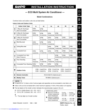
Sanyo SPW-U253GH56 Installation Instruction (91 pages)
ECO Multi System Air Conditioner
Brand:
Sanyo
| Category:
Air Conditioner
| Size: 1.06 MB
Table of Contents
Table of Contents
4
Please Read before Starting
2
Special Precautions
2
Check of Density Limit
3
General
6
Tools Required for Installation (Not Supplied)
6
Accessories Supplied with Unit
6
Type of Copper Tube and Insulation Material
6
Additional Materials Required for Installation
6
Tubing Length
10
Tubing Size
11
Straight Equivalent Length of Joints
11
Additional Refrigerant Charge
12
Installing the Distribution Joint
12
Optional Distribution Joint Kits
13
Selecting Refrigerant Tubing Size and Calculating the Amount of Additional Charge
14
Selecting the Installation Site
15
Indoor Unit
15
Outdoor Unit
16
Type
16
Air-Discharge Chamber for Top Discharge
17
Dimensions of Snow/Wind-Proof Ducting and Refrigerant Tubing Space for Installation
17
Installing the Unit in Heavy Snow Areas
17
Precautions When Installing in Heavy Snow Areas
17
Dimensions of Snow / Wind Ducting (48 Type)
18
Type
19
Shield for Horizontal Exhaust Discharge
20
Installing the Outdoor Unit in Heavy Snow Areas
21
Precautions When Installing in Heavy Snow Areas
21
Dimensions of Snow / Wind Ducting (70, 90 Type)
22
How to Install the Indoor Unit
23
1-Way Air Discharge Semi-Concealed Type (as Type)
23
Suspending the Indoor Unit
23
Placing the Unit Inside the Ceiling
24
Installing the Drain Piping
25
Checking the Drainage
27
2-Way Air Discharge Semi-Concealed Type (S Type)
28
Suspending the Indoor Unit
28
Installing the Drain Piping
29
Placing the Unit Inside the Ceiling
29
Checking the Drainage
31
4-Way Air Discharge Semi-Concealed Type (X Type)
32
Preparation for Suspending
32
Suspending the Indoor Unit
32
Placing the Unit Inside the Ceiling
33
Installing the Drain Piping
34
Checking the Drainage
35
Wall-Mounted Type (K Type)
36
Removing the Rear Panel from the Unit
36
Selecting and Making a Hole
36
Installing the Rear Panel Onto the Wall
37
Removing the Grille to Install the Indoor Unit
37
Preparing the Tubing
38
Shaping the Tubing
38
Installing the Drain Hose
39
Ceiling-Mounted Type (T Type)
40
Suspending the Indoor Unit
40
Partial Flush Mounting
42
Installing the Drain Piping
43
When Suspending Away from the Ceiling
43
Concealed-Duct Type ( U Type) 3-25. Required Minimum Space for Installation and Service
44
Required Minimum Space for Installation and
44
Suspending the Indoor Unit
45
Installing the Drain Piping
46
Checking the Drainage
47
Increasing the Fan Speed
48
Concealed-Duct High Static Pressure Type (D Type)
49
It Is Recommended that Space Is Provided
49
The Minimum Space for Installation and Service Is
49
This Air Conditioner Is Usually Installed above the
49
Visible from below
49
Suspending the Indoor Unit
50
Installing the Drain Piping
51
Caution for Ducting Work
52
Table
53
A (Length)
53
Floor-Standing Type (F Type)
53
Concealed Floor-Standing Type (FM Type)
53
Dimensions and Part Names
53
Required Minimum Space for Installation and
53
Type
53
66
54
(Hole) Fig
54
Table
54
(Floor-Standing Type)
55
Installing the Refrigerant Tubing
55
Removing and Attaching the Front Panel
55
Refrigerant Tubing
56
Installing the Drain Piping
57
Installing the Remote Controller
57
Fig
58
How to Install the Outdoor Unit
58
Installing the Outdoor Unit
58
Electrical Wiring
59
General Precautions on Wiring
59
Recommended Wire Length and Wire Diameter for Power Supply System
59
Wiring System Diagrams
62
How to Install the Remote Controller (Optional Part)
63
When Using a Wall Box for Flush Mounting
63
Basic Wiring Diagram
66
Wiring System Diagram for Multiple Remote Control
66
Explanation of Alarm Messages
67
How to Install the Weekly Timer (Optional Controller)
69
When Using a Wall Box for Flush Mounting
69
Display at Power on
70
Memory Back up Function for Power Failure Compensation
70
Test Run Setting
70
Wiring Diagram
70
Connecting Narrow Tubing Side
73
How to Process Tubing
73
Connecting Tubing between Indoor and Outdoor Units
74
Connecting Wide Tubing Side
74
Insulating the Refrigerant Tubing
75
Finishing the Installation
76
Taping the Tubes
76
Air Purging
77
(AS Type)
80
1-Way Air Discharge Semi-Concealed Type
80
How to Install the Ceiling Panel
80
How to Use the Stoppers
80
Installing the Ceiling Panel
80
2-Way Air Discharge Semi-Concealed Type (S Type)
81
Before Installing the Ceiling Panel
81
Installing the Ceiling Panel
82
When Removing the Ceiling Panel for Servicing
82
4-Way Air Discharge Semi-Concealed Type (X Type)
83
Before Installing the Ceiling Panel
83
Installing the Ceiling Panel
84
When Removing the Ceiling Panel for Servicing
84
Adjusting the Motor Flap
85
Preparing for Test Run
86
Test Run
86
PCB Setting & Test Run
87
Main Alarm Messages Indicating Unit Malfunction
89
Main Alarm Messages Which Indicate Mis-Wiring
89
Alarm Messages on the Outdoor PCB
90
666
54
Advertisement
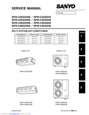
Sanyo SPW-U253GH56 Service Manual (108 pages)
SPLIT SYSTEM Air Conditioner
Brand:
Sanyo
| Category:
Air Conditioner
| Size: 0.68 MB
Table of Contents
Service Manual
1
Please Read before Starting
2
Special Precautions
2
Table of Contents
3
1 Specifications
7
Unit Specifications
8
Major Component Specifications
12
(A) Indoor Unit
12
(B) Outdoor Unit
15
Other Component Specifications
18
Dimensional Data
20
(A) Indoor Unit
20
(B) Outdoor Unit
22
Refrigerant Flow Diagram
24
Operating Range
25
2 Processes and Functions
27
Room Temperature Control
28
(A) Cooling
28
(B) Heating
29
Cold Draft Prevention (Heating Cycle)
30
Automatic Fan Speed (Indoor Unit)
31
(A) Cooling
31
(B) Heating
31
Outdoor Fan Speed Control
32
(A) Cooling
32
(B) Heating
32
Freeze Prevention (Cooling)
33
Condensing Temperature Control (Cooling)
34
Overload Protection (Heating)
35
Discharge Temperature Control (Cooling and Heating)
36
Auto. Mode for Automatic Heating/Cooling Switching
36
Defrosting Control, Outdoor Heat Exchanger Coil (Heating)
38
4-Way Valve, Solenoid Control
39
(A) Normal Control Mode
39
(B) AUTO Control Mode
40
Automatic Restart after Power Interruption
40
Electronic Refrigerant Control Valve
41
Compressor Discharge Gas Temperature
41
(A) Cooling
41
(B) Heating (Except During Defrosting)
41
Compressor Current Detection Circuit
42
Dehumidifying Operation
43
Drain Pump Control
44
Electronic Refrigerant Control Valve Control
45
Voltage Detection Control
46
3 Electrical Data
47
Indoor Unit (Electric Wiring Diagram, Schematic Diagram)
48
Outdoor Unit (Electric Wiring Diagram, Schematic Diagram)
52
4 Service Procedures
61
Troubleshooting
62
Check before and after Troubleshooting
63
General Troubleshooting Flow Chart: Diagnosis and Remedy
65
Meanings of Alarm Messages
67
LED Indication on the Outdoor Unit's P.C.B. Ass'y
69
Symptoms and Parts to Inspect
70
Procedures When a Specific Component Does Not Work
80
Service Functions of Remote Controller
82
Checking the Electrical Components
95
Measurement of Insulation Resistance
95
Checking the Protective Devices
97
Checking the Electrical Parts
98
Sensor and Solenoid Layout Diagram
101
Thermistor Characteristic Curve
103
PCB Setting
104
Address Setting Method
105
Automatic Address Setting Method
106
Displaying Indoor / Outdoor Unit Combination Numbers
106
Items to Check Prior to Test Run
107
Test Run Procedure
108
Advertisement
Related Products
Sanyo SPW-U255H
Sanyo SPW-U255HN
Sanyo SPW-U255SH
Sanyo SPW-U255SHT
Sanyo 2-WAY ECO-i SPW-U255XH
Sanyo SPW-U605HN
Sanyo 2-WAY ECO-i SPW-UR184SXH56B
Sanyo Mini ECO-i SPW-UR164GXH56(A/B)
Sanyo 2-WAY ECO-i SPW-UR304SXH56B
Sanyo SPW-UR254SH56(A/B)
Sanyo Categories
Projector
TV
Air Conditioner
Security Camera
LCD TV
More Sanyo Manuals
Login
Sign In
OR
Sign in with Facebook
Sign in with Google
Upload manual
Upload from disk
Upload from URL