Sign In
Upload
Manuals
Brands
rotork Manuals
Controller
Modbus IQT Pro
rotork Modbus IQT Pro Manuals
Manuals and User Guides for rotork Modbus IQT Pro. We have
1
rotork Modbus IQT Pro manual available for free PDF download: Technical Manual
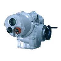
rotork Modbus IQT Pro Technical Manual (76 pages)
RTU Actuator Control Mk2 Option Card
Brand:
rotork
| Category:
Controller
| Size: 2.36 MB
Table of Contents
Table of Contents
3
1 Introduction
7
Fig 1: the Modbus Module Option Card Actuator Compatibility
7
General
8
Fig 2: the Types of Modbus Module Mk2 Option Card
8
2 Modbus Option Card Properties
9
Mechanical Properties
9
Fig 3: the Modbus Single Channel NIC, Showing the Network Connector
9
Fig 5: the Interface Card (si Pro and EH Pro Actuators, Q Is Similar, See Section 3.2)
10
Fig 6: the Interface Card (IQ Pro and IQT Pro Actuators)
10
Electrical Properties
11
Operation and Storage
11
3 Fitting the Modbus Module Option Card
12
Inside an IQ Pro or IQT Pro Actuator
12
Inside a Q Actuator
13
Fig 8: the MFU Module Profiled for the Q Actuator
13
Inside Rompak Actuator
14
Fig 9: the MFU Located in a Rompak Actuator
14
Inside an si or EH Actuator
15
Replacing or Fitting a Modbus Module Option Card
16
4 Rs-485 Data Highway, Connections and Mfu Setup
17
Data Highway
17
Fig 11: Typical RS-485 Data Highway
17
Highway Topology
18
Fig 12: RS-485 Data Highway Topology
18
Cable Types
19
Fig 13: Typical RS-485 Cable
19
Termination Network
20
Fig 14: Termination for RS-485 Highway
20
Inter-Connecting the Highway and Setting up the MFU
21
Fig 15: Termination for RS-485 Highway in Rompak Actuators. the Links Are Shown in the Non- Terminated Position
21
Single Highway with Analogue Input
22
Fig 16: Single Highway + Analogue Input Connections
22
Dual Highway
23
Fig 18: Jumper Settings for Dual Highway Option
23
Fig 17: Dual Highway Connections
23
Single Highway with Internal Repeater
24
Fig 19: Single Highway with Internal Repeater Connections
25
Fig 20: Jumper Settings for Single Highway with Internal Repeater Option
26
5 The Actuator Input and Output Signals
27
Control Outputs
27
Fig 21: Input and Output Data Direction
27
Controls Priority
30
Modbus Control Using Individual Coil Commands
31
Modbus Control Using the ACTCON Register
31
Modbus Control Using the Actuator Position DV Register
31
The IQ 'S' Contacts (Modbus Dos)
32
IQ Modbus Network Control Disable Feature
32
Actuator Digital Input Status Feedback
32
Fig 24: IQ and IQT Relay Outputs DO-1 to DO-4
32
Digital Inputs from All Actuator Types
33
Digital Inputs from IQ and IQT Actuator
36
Digital Inputs from IQT Actuator
37
Actuator Analogue Input Feedback
37
IQ Data Logger Information
38
6 Modbus Communication
40
Electrical Specification
40
Outer Protocol
40
Repeaters
40
Dual Channel Mode
41
7 Modbus Data Base
43
Modbus RTU Message Frame
43
Modbus Address
43
Fig 25: Modbus Transaction Format
43
Function Code Support
44
Broadcast Commands
46
Data Location Offsets
46
Data Locations
46
Data Accessed with Function Code 01 - Read Coils
47
Data Accessed with Function Code 02 - Read Discrete Inputs
47
Data Accessed with Function Code 03 - Read Holding Registers
48
Data Accessed with Function Code 04 - Read Input Registers
50
Data Accessed with Function Code 05 and 15 - Force Single and Multiple Coils
51
Data Accessed with Function Code 06 and 16 - Preset Single and Multiple Registers
51
Data Accessed with Function Code 07 - Read Exception Status
52
Data Accessed with Function Code 08 - Loopback Diagnostic Test
52
Data Accessed with Function Code 17 - Report Slave ID
52
Data Base Summary
53
8 Configuration Registers
55
Actuator Related Configurable Parameter Registers
57
Action on Loss of Communications (Register 7)
57
Limited Range Position Minimum and Maximum (Registers 8 and 9)
57
Fig 26: Limited Range Position Control and Reporting
57
Deadband and Hysteresis (Registers 10 and 14)
58
Fig 27: Deadband and Hysteresis Settings
58
Motion Inhibit Timer (Register11)
59
Auxiliary Input Mask (Register 12)
59
Communications Lost Position (Register 13)
60
Slow Mode Range (Register 15)
60
Valve Jammed Time (Register 16)
60
Manual Movement Travel (Register 17)
61
Watchdog Timeout (Register 18)
61
ESD DI-4/Net Disable (Register 19)
61
Analogue Input Max (Register 20)
61
Communications Fault Timer (Register 21)
61
Modbus Network Related Configurable Parameter Registers
61
Modbus Address (Register 22)
61
Baud Rate (Register 23)
62
Parity and Stop Bits (Register 24)
62
Data Base Format (Register 25)
62
Actuator Tag Name (Register 26 to 31)
62
Return to Defaults
62
9 Setting up and Maintaining the Modbus Module
63
Using a Network Configuration Tool
63
Setting up an IQ or IQT with the Setting Tool
63
Fig 28: Setting Tool Menu Structure and MFU Settable Parameters
64
10 Maintenance and Repair
66
Records
66
11 Troubleshooting
67
12 Appendix A - Modbus Module Mk1 Data Base
69
Introduction
69
Input and Output Signals
69
Control Outputs
69
Digital Input Status Feedback
70
Analogue Input Status Feedback
70
Modbus Communication
71
Modbus Data Base
71
Function Code Support
71
Broadcast Messages
71
Data Locations
72
Configuration
75
Records
75
Advertisement
Advertisement
Related Products
rotork Modbus IQ Pro
rotork Modbus Q
rotork Modbus SI Pro
rotork Modbus EH Pro
rotork Modbus ROMpak
rotork Profibus Modbus Module Mk2
rotork Master Station
rotork MV-1000 Series
rotork MV-1010
rotork MV-1020
rotork Categories
Controller
Valve Positioners
Industrial Equipment
Control Unit
Control Systems
More rotork Manuals
Login
Sign In
OR
Sign in with Facebook
Sign in with Google
Upload manual
Upload from disk
Upload from URL