Sign In
Upload
Manuals
Brands
Panasonic Manuals
Camcorder
AJ-HDC27VP
Panasonic AJ-HDC27VP Manuals
Manuals and User Guides for Panasonic AJ-HDC27VP. We have
4
Panasonic AJ-HDC27VP manuals available for free PDF download: Service Manual, Operating Instructions Manual
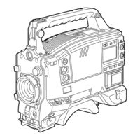
Panasonic AJ-HDC27VP Service Manual (741 pages)
VTR
Brand:
Panasonic
| Category:
Digital Camera
| Size: 70.07 MB
Table of Contents
English
8
Table of Contents
8
1 Servicing Fixtures & Tools
10
How to Use VFK1604 and VFK1611
13
2 Alignment Tape
14
DVCPRO Alignment Tape
14
3 List of Recommended Measuring and Instruments
14
4 Maintenance Schedule
15
5 Layout of the Maintenance Parts & Sensors
16
6 Emergency Eject
17
7 Cleaning Method
18
Cylinder Head Cleaning Method: (Daily)
18
Cylinder Lead Cleaning Method: (Weekly)
18
A/C Head Cleaning Method: (Weekly)
18
Pinch Roller and Capstan Shaft Cleaning Method: (Weekly)
18
Post Cleaning Method: (Weekly)
18
8 Basic Setting Menu Operations
19
Service Menu Operation
19
Design Menu Operation
20
Displaying Sub-Menus and Setting Procedures
21
Setting Menu Configurations
23
9 Service Menu Item Contents
26
Cam Service Menu
26
Cam Design Menu
27
Vtr Service 1/3
29
Vtr Service 2/3
29
Vtr Service 3/3
29
Vtr Design Menu
30
Test Mode
31
Error Log
31
10 Adjustment after Optical Unit Replacement
32
Input the Adjustment Data
32
Electrical Adjustment
32
11 DIAG-MENU Display
33
12 Error Rate Display and Confirmation Method
35
Error Rate Display Method
35
13 Internal Switch Setting Method
36
14 Circuit Board Layout
37
15 PLD Version Upgrade Method
38
Preparation
38
Connection
38
Version-Up Procedures
39
16 Flash Memory Version Upgrade Method
41
Preparation
41
Version Upgrade for CAM_SYS P.C.board
42
Version Upgrade for VTR_SYS P.C.board
44
Version Upgrading for SERVO P.C.board
46
17 Blemish Compensation Method
47
Preparation
47
Connection
47
Compensation Flow
48
Compensation Procedures
49
Remarks
53
Trouble Shooting
54
FAQ (Frequently Asked Question)
54
Disassembly Procedures
56
Disassemblyprocedures Flowchart
56
Removal of the Cassette Cover
56
Removal of the Left Side Panel
56
Removal of the Right Side Panel
56
Removal of the Cassette-Up Unit
57
Removal of the Mechanism Unit
57
Removal of the Cylinder Unit
58
Name of Tape Transportation
62
Table of Test Point
63
Test Point and VR Location
64
Mechanical Adjustment Procedures
65
Post Height Pre-Adjustment
65
Tension Adjustment Flowchart
65
Tension Arm Offset Adjustment
65
Tension Arm Neutral Position Adjustment
66
Tension Arm PLAY and REV Voltage Adjustment and Confirmation
67
Tension Regulator Spring Adjustment
67
REV Tension Confirmation
68
Tension Confirmation
69
Photo Sensor Voltage Adjustment
70
Tape Path Adjustment Procedure
71
Envelope Waveform Adjustment
72
A/C Head Adjustment
74
A/C Head Tilt Adjustment
76
A/C Head Height Adjustment
76
A/C Head Tilt Confirmation
77
A/C Head Height Confirmation
80
REV (-1) Mode Setting Procedure
80
CTL Self Recording Level Confirmation
80
PLAY Tape Path Limit Confirmation
81
Confirmation of Envelope on REV, REW and FF Mode
81
Confirmation of Play Start Envelope
82
REV Mode Tape Path Limit Confirmation
82
FF, REW Mode Tape Path Limit Confirmation
83
Screw Lock Tight of A/C Head and T3, T4 Post
83
Confirmation of Tape Damage for Long Playback
83
LISTA Adjustment Procedures
84
LISTA Connection and Boot up
85
How to Entry the Attachment Data of Alignment Tape
87
LISTA Sensitivity Adjustment and Sensitivity Detection
88
LISTA Linearity Adjustment and Waving Measurement
90
Self-REC/PLAY Envelope Waveform Confirmation
92
Major Mechanical Parts Replacement & Adjustment Procedures
93
Cylinder Unit Replacement
93
Cleaning Arm Unit Replacement
94
T1 Guide Position Adjustment
94
Adjustment Flow Chart after Cylinder Unit Replacement
95
Supply & Take-Up Reel Rotor Unit Replacement
96
Main Brake Torque Confirmation
97
Pinch Solenoid Replacement
97
Pinch Solenoid Position Adjustment
98
Pinch Arm Unit Replacement
98
Loading Motor Unit Replacement
99
Mode SW Unit Replacement
99
Main Cam Gear Replacement
100
Thrust Screw Replacement and Adjustment
100
S5 Post Base Unit Replacement
101
Tension Arm Unit Replacement
102
S1 Post Loading Arm Unit Replacement & Adjustment
103
T1 Boat Unit Replacement and Adjustment
104
T1 Loading Arm Unit Replacement & Adjustment
106
A/C Head Replacement & Adjustment
106
Cleaner Solenoid Replacement & Adjustment
109
MIC Bas Unit Replacement
110
T4 Post Position Adjustment
110
Optical Unit
112
Initial Setting
112
R, G, B RESET DC Adjustment
112
R, G, B Response Confirmation
113
H1DC Adjustment
113
R, G, B PRE AMP DC Adjustment
114
R, G, B PREPRO Level Adjustment
114
R, G, B SUB Adjustment
115
Camera Main Unit
116
Initial Setting
116
R, G, B TEST PED Adjustment
116
R, G, B Test Signal Level Adjustment
116
R, G, B AD Level Adjustment
117
R, G, B Pre Knee-Point Adjustment
117
IRE PED Adjustment
118
R, G, B PRE AMP DC Adjustment
118
R, G, B PREPRO Level Adjustment (COARSE)
119
R, G, B PED TRACK Adjustment
119
R, G, B PREPRO Level Adjustment (FINE)
120
Confirmation of the Modulation Factor
120
R, G, B W/S Offset Adjustment (1)
121
R, G, B W/S Offset Adjustment (2)
121
R, G, B W/S Offset Adjustment (3)
122
R, G, B W/S Offset Adjustment (4)
122
Digital White Shading Adjustment
123
Digital Dark Shading Adjustment
123
Flare Adjustment
124
R, B GAMMA Adjustment
124
ND Compensation Adjustment
125
Video out
126
VF y Output Adjustment
126
SYNC Output Level Adjustment
126
VTR Playback Output Level Adjustment
126
Vtr Syscon
127
Initial Setting of DIP SW (Release Data Saving Prohibition)
127
Power
127
Confirmation of the Voltage
127
Servo
127
T and S Reel Torque Offset Adjustment
127
Adjustment of the Tape Beginning and End Detection Sensitivity
128
CTL AMP Offset Voltage Adjustment
128
PG Shifter Adjustment and Confirmation
128
Rf Eq
129
DRC Input Level Adjustment
129
ATF Input Level Adjustment
129
HSE Input Adjustment
130
PLAY Error Rate Confirmation (Manual Adjustment)
130
REC Signal Detection System Position Adjustment
131
REC Signal Detection System Level Adjustment
131
REC Signal Detection System Operation Confirmation
133
Audio Lcd
134
Initial Setting
134
Real Time Clock Adjustment
134
REC Level Adjustment
134
Audio Level Meter Adjustment
135
Test Tone Adjustment
135
CUE REC Level Adjustment
135
CUE REC Current Adjustment
135
TP, VR and SW Location
136
Audio Lcd P.C.board (Vep84331B)
136
Video out P.C.board (Vep23500B)
137
Vtr Syscon P.C.board (Vep86303C)
137
Servo P.C.board (Vep82224B)
138
Video Main P.C.board (Vep83462C)
139
Dsp Main P.C.board (Vep23530B)
140
Vtr Mother P.C.board (Vep80B10A)
141
Rf Eq P.C.board (Vep87104B)
141
Cue P.C.board (Vep84353A)
142
Pre Process P.C.board (Vep23534B)
142
Hd Sdi Tx P.C.board (Vep83460B)
143
Camera Syscon P.C.board
143
Unknown
145
Overall Block Diagram
146
CCD Sensor/Tg (CCD Pulse)/Drive Block Diagram
147
Pre Process/Pre Amp Block Diagram
148
Dsp Main/Memory Block Diagram
149
Video out Block Diagram
150
Hd Buffer Block Diagram
151
Rf Eq Block Diagram
152
Hd Sdi Tx/Video Main Block Diagram
153
Audio Lcd/Cue Block Diagram
154
Servo Block Diagram
155
Camera Syscon Block Diagram
156
Vtr Syscon/Sd Card Block Diagram
157
Power Main/Sub Block Diagram
158
Vep26234C
192
Vtr Mother P.C.board (Vep80B10A)
291
Head Buff P.C.board (Vep85179B)
303
Sd Card P.C.board (Vep23532A)
320
Memory P.C.board (Vep23531B)
320
CCD Sensor P.C.board (Vep20854A)
398
Tg P.C.board (Vep20855B)
400
Drive P.C.board (Vep20856A)
401
Pre Amp P.C.board (Vep20857A)
402
Pre Process P.C.board (Vep23534B)
403
Dsp Main P.C.board (Vep23530B)
404
Camera Syscon P.C.board (Vep26234C)
406
Video out P.C.board (Vep23500B)
407
Head Buff P.C.board (Vep85179B)
408
Rf Eq P.C.board (Vep87104B)
409
Vtr Syscon P.C.board (Vep86303C)
500
Cue P.C.board (Vep84353A)
505
Hd Sdi Tx P.C.board (Vep83460B)
506
Rear Sw P.C.board (Vep80B45A)
506
Memory P.C.board (Vep23531B)
507
Servicing Fixtures & Tools
508
Mechanical Chassis Assembly (1)
554
Mechanical Chassis Assembly (2)
555
Chassis Frame Assembly (1)
558
Chassis Frame Assembly (2)
559
Chassis Frame Assembly (3)
560
Cassette Compartment Assembly
564
Packing Parts Assembly
566
Advertisement
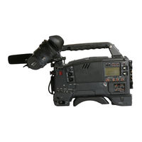
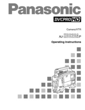
Panasonic AJ-HDC27VP Operating Instructions Manual (119 pages)
VTR
Brand:
Panasonic
| Category:
Digital Camera
| Size: 3.18 MB
Table of Contents
Table of Contents
3
Cam Main Menu
4
Introduction
5
Features
5
Features of the Camera Unit
5
Features of the VTR Unit
7
System Configuration
8
Parts and Their Functions
9
Power Supply Section
9
Accessory Mounting Section
9
Audio Function Section
10
Viewfinder Section
12
Shooting (Recording)/Playback Function Section
13
Warning/Status Display Section
18
Menu Operation Section
19
Time Code Related Section
19
Power Supply
21
Using the Anton/Bauer Battery Pack
21
Using the Panasonic AU-BP402 Battery Pack
22
Using the Sony NP-1 Battery Pack
23
Using the Sony BP-90 Battery Pack
23
Using the Sony BP-L60/L90 Lithium-Ion Battery
24
Using an AC Power Supply
24
When the AJ-B75 AC Adapter Is Used
24
Attaching the Lens
25
Adjusting the Lens Flange
26
Adjusting the White Shading
27
Adjusting the Viewfinder
29
Attaching the Viewfinder
29
Detaching the Viewfinder
29
Adjusting the Viewfinder Position
30
Audio Input Preparation
31
When Attaching a Microphone to the Viewfinder (Optional Accessory) for Use
31
When Attaching a Microphone to the Main Unit for Use
32
MIC in Jack
33
When Connecting a Microphone to the AUDIO in Connector
33
When Using a Wireless Microphone
34
When Connecting Audio Components
34
Mounting the Unit on a Tripod
35
Attaching the Shoulder Strap
36
Adjusting the Shoulder Pad Position
36
Attaching the Rain Cover
37
Connecting the Extension Control Unit
37
Viewfinder Lamp Displays
38
Setting the Lamp Displays
39
Viewfinder Screen Status Displays
40
Selecting the Display Items
42
Display Modes and Setting Change Messages
43
Switching the Display Mode
44
Setting the Marker Displays
44
Setting the Camera ID
44
Screen Displays
45
Remaining Battery Charge and Audio Channel Level and Remaining Tape Displays
45
Displays Relating to Errors and Warnings
45
Displays Relating to Time Codes
45
Adjusting the Date and Time
46
Adjustments and Setup Using the Setting Menus
46
Adjusting the White Balance and Black Balance
47
Adjusting the White Balance
47
Adjusting the Black Balance
51
Setting the Electronic Shutter
52
Shutter Modes
52
Setting the Shutter Mode and Speed
52
Changing the Shutter Speed and Mode Selection Range
53
Setting the Synchro Scan Mode
53
Variable Frame Rate
54
Setting the Frame Rate
54
Scan Reverse
55
Setting the Scan Reverse
55
Adjusting the Audio Level
56
Manual Audio Level Adjustments
56
Limiter
56
Setting the Time Data
57
Setting the User's Bit
57
Setting the Time Code
58
Externally Locking the Time Code
59
How to Use the User Data
60
Setup Card Operations
61
Formatting the Setup Card
62
Saving the Data Settings on the Card
63
Loading the Data Saved on the Card
65
Cassette Tapes
66
Recording
67
Shooting
68
Scene-To-Scene Continuity
69
Playback
70
(Checking What Has Been Recorded)
70
Rec Review
70
Color Playback
70
Lens RET Button Functions
70
Other VTR Functions
71
NEWS REC Function
71
RETAKE Function
71
INTERVAL REC (Intermittent Recording) Function
71
Menu Operations
72
Basic Setting Menu Operations
73
Displaying Sub-Menus and Deciding on Settings
74
Setting Menu Configuration
75
Setting Menu Screens
79
CAM MAIN MENU 1 Screen
79
CAM MAIN MENU 2 Screen
79
CAM MAIN MENU 3 Screen
79
CAM MAIN MENU 4 Screen
79
Cam Main Menu
80
ROP Screen
80
MATRIX Screen
80
COLOR CORRECTION 1 Screen
81
COLOR CORRECTION 2 Screen
81
LOW SETTING Screen
82
MID SETTING Screen
82
HIGH SETTING Screen
83
ADDITIONAL DTL1 Screen
83
ADDITIONAL DTL2 Screen
83
SKIN TONE DTL Screen
84
KNEE/LEVEL Screen
84
GAMMA Screen
85
CAMERA SETTING Screen
85
Cam Main Menu
85
VF DISPLAY Screen
86
VF MARKER Screen
86
VF INDICATOR Screen
87
CAMERA ID Screen
87
SHUTTER SPEED Screen
88
LED Screen
88
CAMERA SW MODE Screen
89
SUPER GAIN Screen
89
FRAME MODE Screen
89
Cam Main Menu
90
CAM CARD READ/WRITE Screen
90
CAM CARD R/W SELECT Screen
90
GENLOCK/IRIS Screen
91
LENS ADJ Screen
91
CAM USER MENU SELECT 1 Screen
92
CAM USER MENU SELECT 2 Screen
92
CAM USER MENU SELECT 3 Screen
92
BLACK SHADING Screen
93
WHITE SHADING Screen
93
FLARE Screen
93
COLORIMETRY Screen
93
INITIALIZE Screen
94
DIAGNOSTIC Screen
94
EVALUATION Screen
94
OPTION Screen
94
VTR MAIN MENU Screen
96
FUNCTION Screen
97
BATTERY/TAPE Screen
98
BATTERY SETTING Screen
99
VTR VF INDICATOR Screen
100
MIC/AUDIO Screen
100
TC/UB Screen
102
TIME DATE Screen
104
VTR USER MENU SELECT Screen
104
VTR CARD READ/WRITE Screen
104
VTR INITIALIZE Screen
104
DIAGNOSTIC Screen
104
Vtr User Menu Select
105
FUNCTION Screen
105
BATTERY/TAPE Screen
105
VTR VF INDICATOR Screen
106
MIC/AUDIO Screen
106
TC/UB Screen
106
Warning System
107
Emergency Eject
109
Error Codes
109
Maintenance
110
Condensation
110
Head Cleaning
110
Cleaning Inside the Viewfinder
110
Phenomena Inherent to CCD Cameras
110
Replacing the Backup Battery
110
Inspections Prior to Shooting
111
Preparation for Inspection
111
Inspecting the Camera Unit
111
Inspecting the Viewfinder
112
Inspecting the Aperture and Zoom Functions
113
Inspecting the VTR Unit
113
Specifications
115
Panasonic AJ-HDC27VP Operating Instructions Manual (116 pages)
Camera/VTR
Brand:
Panasonic
| Category:
Camcorder
| Size: 3.15 MB
Table of Contents
Table of Contents
3
Cam Main Menu
4
Introduction
5
Features
5
Features of the Camera Unit
5
Features of the VTR Unit
7
System Configuration
8
Parts and Their Functions
9
Power Supply Section
9
Accessory Mounting Section
9
Audio Function Section
10
Viewfinder Section
12
Shooting (Recording)/Playback Function Section
13
Warning/Status Display Section
18
Menu Operation Section
19
Time Code Related Section
19
Power Supply
21
Using the Anton/Bauer Battery Pack
21
Using the Panasonic AU-BP402 Battery Pack
22
Using the Sony NP-1 Battery Pack
23
Using the Sony BP-90 Battery Pack
23
Using the Sony BP-L60/L90 Lithium-Ion Battery
24
Using the AC Power Supply
24
When the AJ-B75 AC Adapter Is Used
24
Attaching the Lens
25
Adjusting the Lens Flange
26
Adjusting the White Shading
27
Adjusting the Viewfinder
29
Attaching the Viewfinder
29
Detaching the Viewfinder
29
Adjusting the Viewfinder Position
30
Audio Input Preparation
31
(Optional Accessory) for Use
31
When Attaching a Microphone to the Main Unit for Use
32
When Connecting a Microphone to the MIC in Jack
33
When Connecting a Microphone to the AUDIO in Connector
33
When Using a Wireless Microphone
34
When Connecting Audio Components
34
Mounting the Unit on a Tripod
35
Attaching the Shoulder Strap
36
Adjusting the Shoulder Pad Position
36
Attaching the Rain Cover
37
Connecting the Extension Control Unit
37
Viewfinder Lamp Displays
38
Setting the Lamp Displays
39
Viewfinder Screen Status Displays
40
Selecting the Display Items
42
Display Modes and Setting Change Messages
43
Switching the Display Mode
44
Setting the Marker Displays
44
Setting the Camera ID
44
Screen Displays
45
Remaining Battery Charge and Audio Channel Level and Remaining Tape Displays
45
Displays Relating to Errors and Warnings
45
Displays Relating to Time Codes
45
Adjusting the Date and Time
46
Adjustments and Setup Using the Setting Menus
46
Adjusting the White Balance and Black Balance
47
Adjusting the White Balance
47
Adjusting the Black Balance
51
Setting the Electronic Shutter
52
Shutter Modes
52
Setting the Shutter Mode and Speed
52
Changing the Shutter Speed and Mode Selection Range
53
Setting the Synchro Scan Mode
53
Adjusting the Audio Level
54
Manual Audio Level Adjustments
54
Limiter
54
Setting the Time Data
55
Setting the User's Bit
55
Setting the Time Code
56
Externally Locking the Time Code
57
How to Use the User Data
58
Setup Card Operations
59
Formatting the Setup Card
60
Saving the Data Settings on the Card
61
Loading the Data Saved on the Card
63
Cassette Tapes
64
Recording
65
Shooting
66
Scene-To-Scene Continuity
67
Playback
68
(Checking What Has Been Recorded)
68
Rec Review
68
Color Playback
68
Lens RET Button Functions
68
Other VTR Functions
69
NEWS REC Function
69
RETAKE Function
69
INTERVAL REC (Intermittent Recording) Function
69
Menu Operations
70
Basic Setting Menu Operations
71
Displaying Sub-Menus and Deciding on Settings
72
Setting Menu Configuration
73
Setting Menu Screens
77
CAM MAIN MENU 1 Screen
77
CAM MAIN MENU 2 Screen
77
CAM MAIN MENU 3 Screen
77
CAM MAIN MENU 4 Screen
77
Cam Main Menu
78
ROP Screen
78
MATRIX Screen
78
COLOR CORRECTION 1 Screen
79
COLOR CORRECTION 2 Screen
79
LOW SETTING Screen
80
MID SETTING Screen
80
HIGH SETTING Screen
81
ADDITIONAL DTL1 Screen
81
ADDITIONAL DTL2 Screen
81
SKIN TONE DTL Screen
82
KNEE/LEVEL Screen
82
GAMMA Screen
83
CAMERA SETTING Screen
83
Cam Main Menu
83
VF DISPLAY Screen
84
VF MARKER Screen
84
VF INDICATOR Screen
85
CAMERA ID Screen
85
SHUTTER SPEED Screen
86
LED Screen
86
CAMERA SW MODE Screen
87
SUPER GAIN Screen
87
Cam Main Menu
87
CAM CARD READ/WRITE Screen
88
CAM CARD R/W SELECT Screen
88
GENLOCK/IRIS Screen
89
LENS ADJ Screen
89
CAM USER MENU SELECT 1 Screen
90
CAM USER MENU SELECT 2 Screen
90
CAM USER MENU SELECT 3 Screen
90
BLACK SHADING Screen
91
WHITE SHADING Screen
91
FLARE Screen
91
COLORIMETRY Screen
91
INITIALIZE Screen
92
DIAGNOSTIC Screen
92
EVALUATION Screen
92
OPTION Screen
92
VTR MAIN MENU Screen
94
FUNCTION Screen
95
BATTERY/TAPE Screen
96
BATTERY SETTING Screen
97
VTR VF INDICATOR Screen
98
MIC/AUDIO Screen
98
TC/UB Screen
100
TIME DATE Screen
102
VTR USER MENU SELECT Screen
102
VTR CARD READ/WRITE Screen
102
VTR INITIALIZE Screen
102
DIAGNOSTIC Screen
102
Vtr User Menu Select
103
FUNCTION Screen
103
BATTERY/TAPE Screen
103
VTR VF INDICATOR Screen
104
MIC/AUDIO Screen
104
TC/UB Screen
104
Warning System
105
Emergency Eject
107
Error Codes
107
Maintenance
108
Condensation
108
Head Cleaning
108
Cleaning Inside the Viewfinder
108
Phenomena Inherent to CCD Cameras
108
Replacing the Backup Battery
108
Inspections Prior to Shooting
109
Preparation for Inspection
109
Inspecting the Camera Unit
109
Inspecting the Viewfinder
110
Inspecting the Aperture and Zoom Functions
111
Inspecting the VTR Unit
111
Specifications
113
Advertisement
Panasonic AJ-HDC27VP Operating Instructions Manual (118 pages)
Camera/VTR
Brand:
Panasonic
| Category:
Camcorder
| Size: 3.18 MB
Advertisement
Related Products
Panasonic AJHDC27A - DVCPRO HD CAMERA
Panasonic AJHDC27H - DVCPRO HD CAMERA
Panasonic AJHDC27V - CAMERA VTR
Panasonic AJHDC27HP - DVCPRO HD CAMERA
Panasonic AJ-HDC27HP/MC
Panasonic AJ-HDC27MC
Panasonic AJ-HDC27HE
Panasonic AJ-HDC27AP
Panasonic AJ-HDC27E
Panasonic AJ-HDC20AP
Panasonic Categories
Camcorder
Air Conditioner
TV
Digital Camera
Cordless Telephone
More Panasonic Manuals
Login
Sign In
OR
Sign in with Facebook
Sign in with Google
Upload manual
Upload from disk
Upload from URL