Sign In
Upload
Manuals
Brands
Nortel Manuals
Switch
Contivity 600
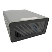
Nortel Contivity 600 Manuals
Manuals and User Guides for Nortel Contivity 600. We have
3
Nortel Contivity 600 manuals available for free PDF download: Installing, Getting Started
Nortel Contivity 600 Installing (158 pages)
Hardware Options for the Contivity Secure IP Services Gateway
Brand:
Nortel
| Category:
Switch
| Size: 2.5 MB
Table of Contents
Table of Contents
7
Preface
17
Before You Begin
17
Text Conventions
18
Acronyms
18
Related Publications
19
How to Get Help
21
Contivity 600 Option Installation
23
Shutting down the System to Add or Replace Hardware
24
Opening the Contivity 600
24
Figure 1 Removing the Screws from the Bottom of the Contivity 600
25
Figure 2 Removing the Chassis from the Steel Enclosure
26
Figure 3 Contivity 600 System Board
27
Installing and Replacing an Option Card
28
Figure 4 Removing the Blank Bracket from the Option Card Slot
29
Figure 5 Inserting the Option Card
30
Figure 6 Securing the Option Card in the Slot
31
Figure 7 Replacing the Chassis in the Steel Enclosure
31
Replacing a DIMM
32
Figure 8 Installing a DIMM
33
Contivity 1100 Option Installation
35
Table 1 Supported Option Cards for the Contivity 1100
35
Figure 9 Contivity 1100 System Board
37
Contivity 1700 and 1600 Option Installation
39
Shutting down the System to Add or Replace Hardware
40
Removing the Front Bezel and Top Cover
41
Figure 10 Removing the Front Bezel
41
Figure 11 Removing the Top Cover
42
Figure 12 Location of Option Card Slots and Dimms on the System Board
43
Attaching the Antistatic Wrist Strap
44
Figure 13 Location of the Grounding Jack for the Antistatic Wrist Strap
44
Installing and Replacing Option Cards
45
Table 2 Supported Option Cards for the Contivity 1700
45
Table 3 Supported Option Cards for the Contivity 1600
45
Figure 14 Removing an Option Card or a Filler Panel
47
Figure 15 Installing an Option Card
48
Installing and Replacing Dimms
49
Figure 16 Replacing the Front Bezel
49
Figure 17 Installing and Removing a DIMM in a Contivity 1700 or 1600
51
Figure
51
Contivity 1740 Option Installation
53
Shutting down the System to Add or Replace Hardware
54
Removing the Front Bezel and Top Cover
55
Figure 18 Removing the Front Bezel
55
Figure 19 Removing the Top Cover
56
Figure 20 Location of Option Card and DIMM Slots on the System Board
57
Attaching the Antistatic Wrist Strap
58
Figure 21 Location of the Grounding Jack for the Antistatic Wrist Strap
58
Installing and Replacing Option Cards
59
Table 4 Supported Option Cards for the Contivity 1740
59
Figure 22 Installing and Removing an Option Card
61
Figure 23 Replacing the Front Bezel
62
Installing and Replacing Dimms
63
Figure 24 Installing and Removing a DIMM
64
Contivity 2700 and 2600 Option Installation
67
Shutting down the System to Add or Replace Hardware
68
Removing the Front Bezel and Top Cover
69
Figure 25 Removing the Front Bezel
69
Figure 26 Removing the Top Cover
70
Figure 27 Location of Option Card Slots and Dimms on the System Board
71
Attaching the Antistatic Wrist Strap
72
Figure 28 Location of the Grounding Jack for the Antistatic Wrist Strap
72
Installing and Replacing Option Cards
73
Table 5 Supported Option Cards for the Contivity 2700
73
Table 6 Supported Option Cards for the Contivity 2600
74
Figure 29 Installing and Removing an Option Card
75
Installing and Replacing Dimms
77
Table 7 Base and Maximum Memory for the Contivity 2600 and 2700
77
Contivity 4500 Option Installation
81
Opening the Contivity 4500
81
Figure 33
83
Contivity 4500 System Board Layout
84
Installing and Replacing Option Cards
86
Table 8 Supported Option Cards for the Contivity 4500
86
Installing and Replacing Dimms
88
Replacing a Power Supply
90
Figure 37
90
Replacing a Hard Disk Drive
91
Figure
91
Contivity 4600 Option Installation
93
Opening the Contivity 4600
93
Contivity 4600 System Board Layout
96
Installing and Replacing Option Cards
97
Table 9 Supported Option Cards for the Contivity 4600
97
Installing and Replacing Dimms
99
Figure
99
Replacing a Power Supply
100
Figure
100
Replacing a Hard Disk Drive
102
Contivity 5000 Option Installation
105
Preparing to Install Hardware Options
106
Option Cards, Dimms, and Fan Trays
106
Power Supplies
106
Removing the Front Bezel
108
Removing the Top Cover
110
Table 10 Supported Option Cards for the Contivity 5000
113
Replacing the Front Bezel
116
Removing a Power Supply
121
Removing a Hard Disk Drive
124
Removing a Fan Tray
127
10/100BASE Ethernet Interface Card
133
Table 11 10/100BASE Ethernet Port Pinouts (All Models Except Contivity 1100)
134
Table 12 10/100BASE Ethernet Port Pinouts (Contivity 1100 Only)
134
1000BASE-T Ethernet Interface Card
135
1000BASE-SX Ethernet Interface Card
136
Table 13 1000BASE-T Ethernet Port Pinouts
136
Figures
137
Figure 65 ADSL WAN Interface Card
137
Figure 66 ISDN BRI S/T Interface Card
138
Figure 67 ISDN BRI U Interface Card
138
Table 14 ADSL Cable Pinouts
138
Table 15 ISDN BRI S/T Cable Pinouts
139
Table 16 ISDN BRI U Cable Pinouts
139
Figure 68 T1/E1 CSU/DSU WAN Interface Card
140
Table 17 T1/E1 CSU/DSU Cable Pinouts for Crossover Connection
141
Table 18 T1/E1 CSU/DSU Cable Pinouts for Straight-Through Connection
141
Figure 69 Quad T1/E1 CSU/DSU WAN Interface Card
142
Figure 70 V.90 Modem Interface Card
143
Figure 71 Single V.35/X.21 WAN Interface Card
143
Table 19 V.90 Modem Cable Pinouts
143
Table 20 V.35 Cable Pinouts
144
Table 21 X.21 Cable Pinouts
145
Figure 72 Dual V.35 WAN Interface Card
147
Table 22 DB26-To-V.35 Cable Pinouts
148
Figure 73 HSSI WAN Interface Card
149
Table 23 T3 Cable Pinouts
149
Figure 74 Serial Cable Adapter for Connection to Modem (DB9-To-DB25)
151
Table 24 Null Modem Adapter Cable Pinouts
152
Advertisement
Nortel Contivity 600 Installing (80 pages)
Brand:
Nortel
| Category:
Network Hardware
| Size: 0.93 MB
Table of Contents
Table of Contents
7
Before You Begin
13
Preface
13
Acronyms
14
Text Conventions
14
Related Publications
15
How to Get Help
16
Description of the Contivity 600
17
Introducing the Contivity 600
17
Figure 1 Front View of the Contivity 600
18
Preparing to Install the Contivity 600
18
Cables
19
Shipment Contents
19
Table 1 Items Shipped with the Contivity 600
19
Installing the Chassis
20
Site Requirements
20
Cabling the Gateway and Turning the Power on
21
Connecting Communications Cables
22
Table 2 Interfaces and Cables for the Contivity 600
22
Figure 2 Rear View of the Contivity 600
23
Connecting the Power Cord
24
Table 3 Power Cord Requirements
24
Understanding the Leds
25
Figure 3 Front Panel Leds
26
Front Panel Leds
26
Table 4 Front Panel LED Indicators
26
Figure 4 Leds on the System 10/100BASE Ethernet Port
27
Leds on the System 10/100BASE Ethernet Ports
27
Table 5 LED Indicators on the System 10/100BASE Ethernet Port
27
10/100BASE Ethernet Interface Card Leds
28
Figure 5 Leds on the 10/100BASE Ethernet Interface Card
28
Table 6 LED Indicators on the 10/100BASE Ethernet Interface Card
28
ADSL WAN Interface Card Leds
29
Figure 6 Leds on the ADSL WAN Interface Card
29
Table 7 LED Indicators on the ADSL WAN Interface Card
29
Figure 7 Leds on the T1/E1 CSU/DSU WAN Interface Card
30
T1/E1 CSU/DSU WAN Interface Card Leds
30
Table 8 LED Indicators on the T1/E1 CSU/DSU WAN Interface Card
30
Figure 8 Leds on the Single V.35/X.21 WAN Interface Card
31
Single V.35/X.21 WAN Interface Card Leds
31
Table 9 LED Indicators on the Single V.35/X.21 WAN Interface Card
31
Configuring the Management IP Interface
33
Required Information
34
System Requirements
34
Using the IP Address Configuration Utility
34
Figure 9 Icon for the IP Address Configuration Utility
35
Running the IP Address Configuration Utility
35
Figure 10 IP Address Configuration Utility Dialog Box
36
Using the Serial Interface
37
Testing the Configuration
41
Figure 11 Welcome Screen
42
Troubleshooting
43
Installing Option Cards and Dimms
45
Opening the Contivity 600
46
Shutting down the System to Add or Replace Hardware
46
Figure 12 Removing the Screws from the Bottom of the Contivity 600
47
Figure 13 Removing the Chassis from the Steel Enclosure
48
Figure 14 Contivity 600 System Board
49
Installing and Replacing an Option Card
50
Figure 15 Removing the Blank Bracket from the Option Card Slot
51
Figure 16 Inserting the Option Card
52
Figure 17 Securing the Option Card in the Slot
53
Figure 18 Replacing the Chassis in the Steel Enclosure
53
Replacing a DIMM
54
Figure 19 Installing a DIMM
55
Chapter 5 Using Recovery Mode
57
Figure 20 Recovery Diskette Screen
59
Technical Specifications
63
Chassis Specifications
63
Table 10 Physical, Electrical, and Environmental Specifications
63
System Ports
64
10/100BASE Ethernet LAN Port
64
Figure 21 10/100BASE Ethernet Connector
64
Serial Port
65
Table 11 10/100BASE Ethernet Port Pinouts
65
Table 12 Multiple DB9 and DB25 Connector Pinouts
65
Modem Cable Specifications
66
Figure 22 Modem Cable (9-Pin D-Sub Plug to RS-232-C Modem Plug)
66
Table 13 Modem Cable Pinouts
66
Hardware Option Cards
67
10/100BASE Ethernet Interface Card
67
Figure 23 10/100BASE Ethernet Interface Card
67
ADSL WAN Interface Card
68
Figure 24 ADSL WAN Interface Card
68
Table 14 ADSL Cable Pinouts
68
ISDN BRI Interface Card
69
Figure 25 ISDN BRI S/T Interface Card
69
Figure 26 ISDN BRI U Interface Card
69
Table 15 ISDN BRI S/T Cable Pinouts
70
Table 16 ISDN BRI U Cable Pinouts
70
T1/E1 CSU/DSU WAN Interface Card
71
Figure 27 T1/E1 CSU/DSU WAN Interface Card
71
Table 17 T1/E1 CSU/DSU Cable Pinouts for Crossover Connection
72
Table 18 T1/E1 CSU/DSU Cable Pinouts for Straight-Through Connection
72
Single V.35/X.21 WAN Interface Card
73
Figure 28 Single V.35/X.21 WAN Interface Card
73
Table 19 V.35 Cable Pinouts
73
Table 20 X.21 Cable Pinouts
75
V.90 Modem Interface Card
76
Figure 29 V.90 Modem Interface Card
76
Table 21 V.90 Modem Cable Pinouts
76
Index
77
Nortel Contivity 600 Getting Started (68 pages)
VPN Switch for branch offices
Brand:
Nortel
| Category:
Switch
| Size: 0.65 MB
Table of Contents
Table of Contents
7
Conventions
13
Documentation
13
Preface
13
Related Publications
14
Acronyms
15
Text
15
Hard-Copy Technical Manuals
16
How to Get Help
17
User Interface Help Button
17
Introducing the Contivity 600
19
Figure 1 Front View of the Contivity 600
20
Table 1 Components and Accessories of a Contivity 600
21
Chapter 2 Cabling and LEDS
23
Connecting the Cables
24
Figure 2 Back View of the Contivity 600
24
Power Cord Requirements
25
Current Rating
25
Wall Outlet Connector
25
Power Supply Connector
25
Cord Length and Flexibility
25
LAN Interface Connections
26
Figure 3 10/100BASE-TX Pinouts
26
Single WAN Interface V.35 or X.21 (Optional)
27
Figure 4 Single V.35/X.21 WAN Interface
27
Table 2 DB28S-To-V.35 Cable Pinouts
28
Table 3 DB28S-To-X.21 Cable Pinouts
29
T1 CSU/DSU WAN Interface
30
Figure 5 T1 CSU/DSU Interface
30
Table 4 T1 CSU/DSU Cable Pinouts
31
Serial Interface Cable
32
Table 5 Multiple DB9 and DB25 Connector Pinouts
32
Understanding the Leds
33
Front Panel Leds
33
Figure 6 Front Panel Leds
33
LAN Leds
34
Figure 7 LAN Port Leds
34
Table 6 LAN Port LED Indicators
34
V.35/X.21 Single Leds
35
Figure 8 Single V.35/X.21 Leds
35
Table 7 Single V.35/X.21 LED Indicators
35
T1 CSU/DSU Leds
36
Figure 9 T1 CSU/DSU Leds
36
Table 8 T1 CSU/DSU LED Indicators
36
Public LAN Leds
37
Figure 10 10/100BASE-TX LAN Leds
37
Table 9 10/100BASE-TX LAN LED Card Indicators
37
Changing Hardware Configurations
39
Removing the Rear of the Chassis to Access the System
40
Figure 11 Removing the Bottom Screws
40
Figure 12 Removing the System from the Casing
41
Figure 13 Removing the Chassis from the Rear of the Contivity
42
Figure 14Photographic View of the Contivity 600 System Board
42
Figure 15 Simplified Drawing of the Contivity 600 Mother Board
43
Figure 16 Removing the Bottom Screws
44
Figure 17 Removing the Chassis
45
Figure 18 Removing a Blank PCI Bracket
46
Figure 19 Removing a Blank Option Card
47
Figure 20 Blank Option Card after Screw Removed
48
Figure 21 Replacing Screw at Right End of the PCI Card
49
Figure 22 Replacing Chassis in Casing
50
Using Recovery Mode
51
Figure 23 Recovery Diskette Display
53
Assigning a System Identity
57
Table 10 Initial Configuration Options
57
Startup Configuration Requirements
58
Management IP Address
58
Subnet Mask
58
Default Gateway
58
IP Address Configuration Utility
59
Requirements
59
Running the IP Configuration Utility
59
Figure 24 the Extnepip.exe Icon
60
Figure 25 the Serial Number Search Display
60
Figure 26 Extranet Address Configuration Utility Display
60
Serial Interface Configuration
61
Prerequisites
62
Procedure
62
Specifications
65
Table 11 Physical Specifications and Operating Environment
65
Index
67
Advertisement
Advertisement
Related Products
Nortel Contivity1510D
Nortel Contivity Extranet Switch 4600
Nortel Contivity Extranet Switch 2500
Nortel Contivity 1600
Nortel COMMISSIONING 8600
Nortel CVX 600
Nortel CVX 1800
Nortel Centillion EtherSpeed II
Nortel Contivity 1100
Nortel Contivity 1050
Nortel Categories
IP Phone
Telephone
Switch
Software
Server
More Nortel Manuals
Login
Sign In
OR
Sign in with Facebook
Sign in with Google
Upload manual
Upload from disk
Upload from URL