Sign In
Upload
Manuals
Brands
Mitsubishi Manuals
Engine
S16R
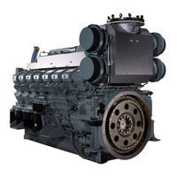
Mitsubishi S16R Manuals
Manuals and User Guides for Mitsubishi S16R. We have
4
Mitsubishi S16R manuals available for free PDF download: Service Manual, Operation & Maintenance Manual, Operating Instructions Manual
Mitsubishi S16R Service Manual (380 pages)
Brand:
Mitsubishi
| Category:
Engine
| Size: 12 MB
Table of Contents
Table of Contents
19
External View
21
Outline of Systems
35
Outline of Fuel System
35
Outline of Lubrication System
36
Outline of Cooling System
37
Outline of Inlet and Exhaust System
41
Contents of Plate and Label
42
Name Plate
42
Caution Plate
42
Emission Certification Label
42
Specifications
43
Maintenance Service Data
51
Engine General
51
Basic Engine
52
Fuel System
59
Lubrication System
62
Cooling System
63
Electrical System
65
Air Start System
68
Tightening Torque Table
69
Tightening Torque for Basic Engine
69
Tightening Torque for Fuel System
71
Tightening Torque for Lubrication System
71
Tightening Torque for Cooling System
72
Tightening Torque for Inlet and Exhaust System
72
Tightening Torque for Electrical System
73
Tightening Torque for Air Start System
73
Tightening Torque for Standard Bolts and Nuts
74
Tightening Torque for Standard Eyebolts
75
Tightening Torque for Standard Union Nuts
75
Tightening Torque Fo Fuel Injection Pipe
75
Cylinder Heads and Valve Mechanisms - Disassemble and Inspect
93
Fuel Inlet Connector - Remove
94
Nozzle Assembly - Remove
94
Valve Clearance - Inspect
94
Fuel Injection Timing - Inspect
95
Rocker Shaft Assembly - Remove
95
Clearance between the Bottom Face of Valve Bridge Pusher and the Top Face of Valve Rotator - Inspect
95
Valve Bridge - Remove
96
Rocker Case - Remove
96
Cylinder Head Assembly - Remove
96
Valve Sinkage - Measure
96
Valve and Valve Spring - Remove
97
Nozzle Gland Stud Bolt and Bridge Guide - Remove
97
Rear Mechanism - Disassemble and Inspect
98
Flywheel Face and Radial Runouts - Measure
99
Governor Drive - Remove
99
Flywheel - Remove
99
Rear Idler Shaft Thrust Collar - Remove
100
Timing Gear Case - Remove
100
Timing Gear Backlash - Measure
100
Rear Idler Gear End Play - Measure
100
Rear Idler Gear - Remove
101
Accessory Drive - Remove
101
Camshaft End Play - Measure
101
Camshaft Gear - Remove
101
Camshaft - Remove
102
Rear Idler Shaft - Remove
102
Rear Plate - Remove
102
Front Mechanism - Disassemble and Inspect
103
Fan Drive Assembly - Remove
104
Damper Face and Radial Runouts - Measure
104
Damper and Crankshaft Pulley - Remove
104
Fan Drive Idler Gear Backlash - Measure
105
Fan Drive Idler Gear End Play - Measure
105
Fan Drive Idler Gear and Fan Drive Idler Shaft - Remove
105
Pump Plate (for Water Pump and Oil Pump) - Remove
106
Oil Pump Gear - Remove
106
Breather Case, Thermostat Bracket - Remove
106
Front Gear Case - Remove
106
Water Pump Bearing Cover and Oil Pump Bearing Cover - Remove
107
Front Idler Gear Backlash - Measure
107
Front Idler Gear End Play - Measure
107
Front Idler Gear - Remove
107
Front Idler Shaft - Remove
108
Coupling - Remove
108
Cylinder Liner, Piston and Connecting Rod - Disassemble and Inspect
109
Piston Protrusion - Measure
110
Connecting Rod End Play - Measure
110
Hard Carbon Deposits on the Upper Part of Cylinder Liner - Remove
110
Connecting Rod Cap - Remove
110
Piston - Remove
111
Piston Ring - Remove
112
Piston Pin and Piston - Remove
113
Cylinder Liner Inside Diameter - Measure
113
Cylinder Liner Flange Protrusion - Measure
113
Cylinder Liner - Remove
113
Crankcase, Crankshaft and Main Bearing - Disassemble and Inspect
114
Crankcase - Invert
115
Crankshaft End Play - Measure
115
Piston Cooling Nozzle - Remove
115
Main Bearing Cap - Remove
115
Crankshaft - Remove
116
Chapter 6 INSPECTION and REPAIR of BASIC ENGINE
119
Cylinder Head and Valve Mechanism - Inspect and Repair
119
Rocker Bushing Inside Diameter and Rocker Shaft Outside Diameter - Measure
119
Rocker Bushing - Replace
119
Valve Stem Outside Diameter and Valve Guide Inside Diameter - Measure
120
Valve Guide - Replace
120
Valve Face - Inspect
121
Valve Face - Reface
121
Valve Seat - Reface
122
Valve Seat - Replace
122
Valve and Valve Seat - Lap
124
Valve Bridge, Bridge Cap, Valve Cotter and Valve Rotator - Inspect
124
Squareness and Free Length of Valve Spring - Measure
125
Tappet - Inspect
125
Pushrod Runout - Measure
126
Nozzle Gland Stud Bolt and Bridge Guide - Inspect and Replace
126
Distortion of Cylinder Head Bottom Surface - Measure
126
Rear Mechanism - Inspect and Repair
127
Rear Idler Bushing Inside Diameter and Rear Idler Shaft Outside Diameter - Measure
127
Rear Idler Bushing - Replace
127
Cam Lift of Cam Lobe - Measure
128
Camshaft Runout - Measure
128
Camshaft Journal Outside Diameter - Measure
128
Camshaft Bushing - Inspect
129
Camshaft Bushing - Replace
129
Front Mechanism - Inspect and Repair
130
Damper - Inspect Visually
130
Pulley - Inspect
130
Fan Drive Idler Bushing Inside Diameter and Fan Drive Idler Shaft Outside Diameter - Measure6-14
130
Fan Drive Idler Bushing - Replace
131
Outside Diameter and Inside Diameter of Oil Pump Drive Bearing Fit - Inspect
131
Front Idler Bushing Inside Diameter and Front Idler Shaft Outside Diameter - Measure
132
Front Idler Bushing - Replace
132
Piston and Connecting Rod - Inspect and Repair
133
Piston - Inspect Visually
133
Piston Weight
133
Piston Outside Diameter - Measure
133
Piston Ring Groove - Inspect
134
Piston Pin Bore Inside Diameter - Measure
134
Piston Ring - Inspect Visually
134
Piston Ring End Gap - Measure
134
Piston Pin Outside Diameter - Measure
135
Connecting Rod Bushing Inside Diameter - Measure
135
Connecting Rod Bushing - Replace
135
Connecting Rod Assembly Weight Rank
138
Connecting Rod Big End Bore Diameter and Roundness - Measure
138
Side Face Width of Connecting Rod Big End - Measure
139
Connecting Rod Big End Serration and Bolt Holes - Inspect
139
Connecting Rod Bearing - Inspect
139
Connecting Rod Bearing Thickness - Measure
140
Connecting Rod Bend and Twist - Inspect
140
Crankcase and Crankshaft - Inspect and Repair
141
Crankcase Top Surface Distortion - Measure
141
Inside Diameter of Main Bearing Housing Bore - Measure
141
Cylinder Liner Fitting Section in Crankcase - Inspect
142
Counterbore in Crankcase - Repair
142
Crankshaft Crankpin and Journal Outside Diameters - Measure
142
Crankpin and Rearmost Crank Main Journal Width - Measure
144
Crankshaft Runout - Measure
145
Crankshaft Gear - Inspect
145
Crankshaft Gear - Replace
145
Oil Seal Slinger - Inspect
146
Oil Seal Slinger - Replace
146
Main Bearing - Inspect
147
Thickness of Main Bearing Shell - Measure
148
Thrust Plate - Inspect
148
Thickness of Thrust Plate - Measure
149
Piston Cooling Nozzle - Inspect
149
Crankshaft and Main Bearing - Install
153
Crankcase - Invert
153
Piston Cooling Nozzle - Install
153
Upper Main Bearing - Install
154
Rear Upper Thrust Plate - Install
154
Crankshaft - Install
155
Front Upper Thrust Plate - Install
155
Lower Main Bearing Shell and Lower Thrust Plate - Install
155
Main Bearing Cap - Install
156
Crankshaft End Play - Measure
157
Crankcase - Invert
157
Cylinder Liner, Piston and Connecting Rod - Assemble
158
Cylinder Liner Protrusion - Measure
158
Cylinder Liner Flange Protrusion - Calculate (When Cylinder Liner Not Installed)
158
Cylinder Liner - Install
159
Cylinder Liner Flange Protrusion - Measure (Cylinder Liner Installed)
160
Cylinder Liner Inside Diameter - Measure
160
Piston and Connecting Rod - Assemble
161
Piston Ring - Install
161
Crankshaft - Turn
162
Piston Installation - Prepare
162
Upper Connecting Rod Bearing - Install
162
Piston- Install
163
Connecting Rod Cap - Install
165
Connecting Rod End Play - Measure
166
Piston Protrusion - Measure
167
Front Mechanism - Assemble
168
Coupling - Install
168
Front Plate - Install
168
Front Idler Shaft - Install
168
Front Idler Gear - Install
168
Front Idler Gear Backlash - Measure
169
Front Idler Gear End Play - Measure
169
Water Pump Bearing Cover and Oil Pump Bearing Cover - Install
169
Water Coupling - Install
169
Fan Drive Idler Gear and Fan Drive Idler Shaft - Install
170
Fan Drive Idler Gear Backlash - Measure
170
Fan Drive Idler Gear End Play - Measure
170
Front Gear Case - Install
171
Front Oil Seal - Install
171
Oil Pump Gear and Pump Plate (for Water Pump and Oil Pump) - Install
171
Breather Case, Thermostat Bracket - Install
172
Damper and Crankshaft Pulley - Install
172
Damper Face and Radial Runouts - Measure
173
Pointer - Install and Adjust
173
Rear Mechanism - Assemble
174
Rear Plate - Install
174
Rear Idler Shaft - Install
174
Camshaft - Install
174
Camshaft Gear - Install
175
Camshaft End Play - Measure
175
Fuel Injection Pump Accessory Drive - Install
175
Rear Idler Gear - Install
176
Rear Idler Gear End Play - Measure
176
Timing Gear Backlash - Measure
177
Timing Gear Case - Install
177
Rear Idler Shaft Thrust Collar - Install
177
Rear Oil Seal - Install
178
Flywheel - Install
178
Governor Drive - Install
178
Flywheel Face and Radial Runouts - Measure
179
Pickup - Install
179
Cylinder Head and Valve Mechanism - Assemble
180
Cylinder Head - Assemble
180
Valve Sinkage - Measure
181
Tappet - Install
181
Liquid Gasket - Apply
181
Cylinder Head Gasket - Install
182
Cylinder Head Assembly - Install
182
Cylinder Head Bolt - Tighten
182
Rocker Case - Install
183
Bridges and Bridge Caps - Install
183
Valve Bridge and Adjusting Screw - Adjust
183
Clearance between the Bottom Face of Valve Bridge Pusher and the Top Face of Valve Rotator - Inspect
184
Rocker Shaft Assembly - Install
184
Valve Clearance - Check and Adjust
185
Fuel Injection Timing - Check and Adjust
185
Valve Timing - Inspect
187
Fuel Injection Nozzle Assembly - Install
189
Fuel System - Remove and Inspect
193
Fuel Injection Pipe and Fuel Leak-Off Pipe - Remove and Inspect
193
Fuel Filter and Fuel Pipe - Remove and Inspect
195
Stop Solenoid - Remove and Inspect
198
Fuel Control Link - Remove and Inspect
201
Governor and Actuator - Remove and Inspect
202
Fuel Injection Pump - Remove and Inspect
205
Fuel System - Disassemble and Inspect
206
Fuel Filter - Disassemble, Inspect and Assemble (Paper Element)
206
Fuel Injection Nozzle - Disassemble and Inspect
209
Fuel Injection Nozzle - Inspect and Adjust
210
Fuel Injection Nozzle - Assemble
213
Fuel Injection Pump Accessory Drive - Disassemble and Inspect
215
Outside Diameter and Inside Diameter of Accessory Drive Bearing Fit - Inspect
217
Fuel Injection Pump Accessory Drive - Assemble
218
Governor Drive - Disassemble and Inspect
221
Outside Diameter and Inside Diameter of Bearing Fit
223
Governor Drive - Assemble
224
Fuel System - Install
226
Fuel Injection Pump - Install
226
Fuel Control Link - Install
230
Stop Solenoid - Install
234
Lubrication System - Remove and Inspect
243
Oil Pipe and Right Oil Cooler - Remove and Inspect
243
Oil Pump, Oil Filter, Oil Pan and Left Oil Cooler - Remove and Inspect
245
Breather and Oil Filler - Remove and Inspect
246
Governor Oil Filter - Remove and Inspect
247
Lubrication System - Disassemble, Inspect and Assemble
248
Oil Pump and Safety Valve - Disassemble and Inspect
248
Oil Pump and Safety Valve - Inspect
250
Oil Pump and Safety Valve - Assemble
252
Oil Filter, Oil Filter Alarm, Relief Valve and Left Oil Cooler - Disassemble and Inspect
253
Oil Filter - Inspect
257
Oil Filter Alarm - Inspect
257
Relief Valve - Inspect
257
Oil Cooler - Inspect
257
Oil Thermostat - Inspect
258
Oil Filter, Oil Filter Alarm, Relief Valve, and Left Oil Cooler - Assemble
259
Oil Filter Cartridge - Install
259
Right Oil Cooler - Disassemble and Inspect
260
Right Oil Cooler - Inspect
260
Right Oil Cooler - Assemble
260
Governor Oil Filter - Disassemble and Inspect
261
Governor Oil Filter - Assemble
262
Lubrication System - Install
263
Oil Pan - Install
263
Oil Pump - Install
263
Cooling System - Remove and Inspect
267
External Cooling System - Remove and Inspect
267
Air Cooler Water Pump - Remove and Inspect
270
Heat Exchanger - Remove and Inspect
271
Water Pipe - Remove and Inspect
273
Thermostat Case and Water Pipe - Remove and Inspect
276
Water Pump - Remove
277
Cooling System - Disassemble, Inspect and Assemble
278
Tension Pulley - Disassemble and Inspect
278
Thermostat - Disassemble and Inspect
280
Thermostat for Jacket Water and Air Cooler - Inspect
282
Water Pump - Disassemble and Inspect
283
Water Pump - Inspect
285
Water Pump - Assemble
286
Air Cooler Water Pump - Disassemble and Inspect
289
Air Cooler Water Pump - Inspect
293
Air Cooler Water Pump- Assemble
294
Fan Drive Assembly - Disassemble and Inspect
301
Fan Drive - Inspect
302
Bushing Ring, Friction Rubber and Grommet - Inspect
302
Oil Seal Sleeve - Inspect
302
Oil Seal Sleeve - Replace
302
Fan Drive - Assemble
303
Cooling System - Install
306
Water Pipe (Air Cooler) - Install
306
Water Pump - Install
306
Inlet and Exhaust Systems - Remove and Inspect
309
Air Duct - Remove and Inspect
309
Insulator - Remove and Inspect
315
Exhaust Pipe - Remove and Inspect
321
Exhaust Manifold - Remove and Inspect
324
Advertisement
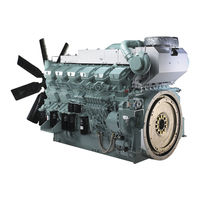
Mitsubishi S16R Operation & Maintenance Manual (216 pages)
Diesel engine
Brand:
Mitsubishi
| Category:
Engine
| Size: 20 MB
Table of Contents
Fig. 1-1 Warning Labels and Their Locations Fig
6
Fig. 1-12 Measures in the Event of Environmental Fig
8
Fig. 1 Location of Nameplate
9
Table 1 Main Specifications
10
Fig. 1 Structure of Service Documents
15
Table of Contents
16
Table 1 List of Models
17
Safety
26
Table 1-1 Types and Meanings of Warning Terms
26
Table 1-2 Meanings of Symbols
27
Operation
33
Fuel
39
Engine Oil
40
Coolant
41
Scheduled Maintenance
42
Inspection and Maintenance
42
Long-Term Storage
51
Transportation
52
Troubleshooting
53
Fig. 1-2 Oil Pressure Switch
57
Fig. 1-3 Thermo Switch
57
Fig. 1-4 Oil Filter Alarm Switch
57
Fig. 1-5 Rotation Detection Pickup
57
Fig. 1-6 Lockout/Tagout (Example)
58
How to Set the Engine to Zero Energy State
59
Working Procedure in Dangerous Areas
59
Works in Dangerous Areas
59
Zero Energy State
59
Body Protection
60
Clothing
60
Fig. 1-7 Clothing
60
Fig. 1-8 Personal Protective Equipment
61
Personal Protective Equipment
61
Product-Specific Precautions
61
Surface Temperature
61
Use of Chemicals
61
Develop the Action Procedure to Obey in the Event of Emergency
62
Keep Everyone Informed about the Emergency Stop Procedure
62
Precautions on Additional Equipment
62
Water Heater
62
Emergency Stop Procedure
63
Fig. 1-9 Emergency Stop Procedure
63
Measures in the Event of Emergency
63
Emergency Stopping Devices Installed During Manufacturing the Generator
64
Fig. 1-10 Measures in the Event of Personal
65
Fig. 1-11 Measures in the Event of Property
65
Measures in the Event of Personal Injuries Resulting from this Engine
65
Measures in the Event of Property Damaging Disasters
65
Fig. 1-13 Measures in the Event of a Fire Disaster
66
Measures in the Event of a Fire Disaster Resulting from this Engine
66
Measures in the Event of Environmental Disaster
66
Measures in the Event of an Earthquake Disaster
67
Education and Training for Safety
68
Fig. 1-16 Education and Training for Safety
68
Occupational Health and Safety Management
68
Operation & Maintenance Manual - Understand and Obey
68
Dangerous and Hazardous Chemicals
69
Fig. 1-17 Dangerous and Hazardous Chemicals
69
Fig. 1-18 Noise
70
Noise
70
Fig. 1-19 Vibration
71
Fig. 1-20 to Maintain Cleanliness and Tidiness
71
To Maintain Cleanliness and Tidiness
71
Vibration
71
Communication with SME
72
Fig. 1-21 Risk of Fire
72
Fig. 1-22 Communication with SME
72
Risk of Fire
72
Engine - Outline
73
Names of Parts
73
S16R-Pta-C
74
S16R-Pta2-C
76
S16R-Ptaa2-C
78
S16R2-Ptaw-C
80
Protection System - Location
82
S16R-Pta-C
83
S16R-Pta2-C
84
S16R-Ptaa2-C
85
S16R2-Ptaw-C
86
Starting and Stopping Devices Installed During Manufacturing the Generator
87
Operation
88
Operation - Outline
88
Daily Check
89
Operational Environment - Check
89
Engine Exterior - Check
91
Engine Oil Level - Check
92
Fuel Control Link - Check
92
Fuel Tank Oil Level - Check
92
Pre-Operation Check
92
Battery - Check
93
Coolant Level - Check
93
Air Cleaner - Check for Clogging
94
Damper Temperature - Check
94
Fig. 3-1 Pre-Cleaner - Check for Clogging
94
Pre-Cleaner - Check for Clogging
94
Table 3-1 Limit Temperature of Damper
94
Air Direct Admission Starting - Check
95
Fig. 3-2 Manual Turning Gear - Check
95
Manual Turning Gear - Check
95
Air Motor Starting - Check
96
Engine Start-Up
97
Self Starter Motor Starting
97
Air Direct Admission Starting
98
Air Motor Starting
98
Fig. 3-3 Air Motor Muffler
98
Warm-Up Operation
99
Operation
100
Checking During Operation
101
Cooling Operation
102
Table 3-2 Checking During Operation
102
Table 4-1 Fuel Specifications
104
Fuel - Handling
105
Fuel - Refill
105
Fuel Quality Standard
106
Table 4-2 Fuel Properties Table (1/2)
106
Table 4-3 Fuel Properties Table (2/2)
107
Engine Oil
109
Engine Oil Grade
109
Engine Oil Viscosity
110
Fig. 5-1 Ambient Temperature and Engine Oil Viscosity
110
Handling Engine Oil
110
Coolant
111
Table 6-1 Water Quality Standard
111
Water to be Used
111
Coolant (LLC) - Handling
112
LLC to be Used
112
Coolant - MIX
113
LLC Concentration (Genuine LLC)
113
LLC Concentration in Coolant - Check
113
Maintenance of LLC
113
Replacement Period
113
Table 6-2 LLC Concentration
113
Fig. 6-1 Freezing Temperature of GLASSY
114
Fig. 6-2 Freezing Temperature of PG GLASSY
114
Fig. 6-3 Tool - Adjust 1
114
Fig. 6-4 Tool - Adjust 2
114
LLC Concentration in Coolant - Measure
114
Tool - Adjust
114
Fig. 6-5 Tool - Adjust 3
115
Fig. 6-6 Tool - Adjust 4
115
Measurement
116
Table 6-3 Scale Conversion Table
116
How to Use the Scheduled Maintenance
118
Scheduled Maintenance
118
Category of Scheduled Maintenance Chart
119
Rating Definition
120
Table 7-1 SME Generator Use Diesel Engine Rating Definition (1/2)
120
Table 7-2 SME Generator Use Diesel Engine Rating Definition (2/2)
121
Scheduled Maintenance for Continuous Use Engine
122
Table 7-3 Scheduled Maintenance for Continuous
122
Table 7-4 Scheduled Maintenance for Continuous
124
Table 7-5 Scheduled Maintenance for Continuous Use Engine (3/3)
124
Scheduled Maintenance for Emergency Use Engine
125
Table 7-6 Schedule Maintenance for Emergency
125
Table 7-7 Scheduled Maintenance for Emergency
126
Table 7-8 Scheduled Maintenance for Emergency
127
Table 7-9 Scheduled Maintenance for Emergency
128
Table 7-11 Scheduled Maintenance for Air Direct Admission Starting
130
Table 7-12 Scheduled Maintenance for Air Motor
130
Inspection and Maintenance
131
Inspection and Maintenance - General Information
131
Precautions for General Inspection and Maintenance
132
Inspection and Maintenance - Prepare
133
Inspection and Maintenance - Prepare (with Engine Switched ON)
133
Belt - Check
134
Engine Body - Check
134
Inspection and Maintenance - Prepare (with Engine Switched OFF)
134
Table 8-1 Type of Belt (V-Belt)
135
Table 8-2 Type of Belt (Ribbed Belt)
135
Belt Tension (Alternator) - Adjust
136
Table 8-3 Ribbed Belt Tensile Force
138
Damper - Check
139
Damper Temperature - Check
139
Table 8-4 Limit Temperature of Damper
139
Table 8-5 Types of Thermo Labels
140
Fuel System - Check
141
Fuel Tank - Check and Service
141
Fuel System - Bleed Air
142
Water Separator - Check and Service
145
Gauze Filter - Clean
146
Fuel Filter - Replace
147
Fuel Control Link - Check
150
Fuel Pipe - Check
152
Engine Oil System - Check
154
Engine Oil - Change
155
Table 8-6 Corresponding Equipment
155
Oil Filter - Replace
159
Bypass Oil Filter - Replace
161
Governor Oil Filter - Replace (Hydraulic Governor Spec)
161
Cooling System - Check
163
Oil Pipe - Check
163
Coolant - Change
164
Corresponding Equipment - Location
164
Table 8-7 Corresponding Equipment - Location
164
Cooling System - Bleed Air
171
Radiator Fins - Check and Clean (Radiator Spec)
172
Resin Fan Inspection (Specifications with Resin Fan)
173
Exhaust Muffler - Drain Water
174
Intake and Exhaust Systems - Check
174
Turbocharger - Check
174
Pre-Cleaner - Check and Service
175
Air Cleaner - Check and Service
176
Battery - Check
177
Electrical System - Check
177
Starter - Check (Self Starter Motor Starting)
177
Air Direct Admission Starting, Air Motor Starting - Check
178
Air Strainer - Drain Water and Clean
178
Alternator - Check
178
Starting Air Motor - Check (Air Motor Starting)
179
Starting Air Tank - Check and Service (Air Direct Admission Starting, Air Motor Starting)
179
Long-Term Storage
180
Storage - Prepare (Rust-Preventive Measure)
180
Storing Engine in Inoperable Condition
180
Maintenance During Storage
182
Restart after Storing
182
Storage
182
Storing Engine in Operable Condition
183
10 Transportation
184
Engine - Lift
184
Precautions on Transportation
184
11 Troubleshooting
187
Precautions on Troubleshooting
187
How to Troubleshoot
188
Starter Does Not Crank or Cranks Slowly, Resulting in Starting Failure
189
Table 11-1 Starter Does Not Crank or Cranks Slowly, Resulting in Starting Failure
189
Troubleshooting
189
Starter Cranks, but Engine Does Not Start
190
Table 11-2 Starter Cranks, but Engine Does Not Start
190
Output Shortage
191
Table 11-3 Output Shortage (1/2)
191
Exhaust Smoke Is White or Blue
192
Table 11-4 Output Shortage (2/2)
192
Table 11-5 Exhaust Smoke Is White or Blue
192
Exhaust Smoke Is Black or Dark Grey
193
Table 11-6 Exhaust Smoke Is Black or Dark Grey
193
Table 11-7 Exhaust Smoke Is Black or Dark Grey
194
Excessive Fuel Consumption
195
Table 11-8 Excessive Fuel Consumption
195
Excessive Engine Oil Consumption
196
Table 11-9 Excessive Engine Oil Consumption
196
Overheating
197
Table 11-10 Overheating
197
Engine Oil Pressure Drop
198
Table 11-11 Engine Oil Pressure Drop
198
Engine Stops
199
Table 11-12 Engine Stops
199
During Normal Operation, Thermo Switch Activated
200
Table 11-13 During Normal Operation, Thermo Switch Activated
200
12 After-Sales Service
201
Inquiry Counter
201
Parts that Reached the Supply Period
201
Supply of Performance Parts for Repair
201
Supply Period
201
When Requesting Repair
201
13 Disposal
202
Disposal Precautions
202
Engine Body - Disposal
204
Wastes Produced During Inspection and Maintenance
204
14 Appendix
205
Engine Oil
205
Engine Oil Quality Standards
206
Table 14-1 Engine Oil Quality Standards
206
Service Limit for Engine Oil Properties
207
Service Limits for Engine Oil
207
Engine Oil Service Limits for Emergency Use
208
Table 14-2 Engine Oil Properties
208
Table 14-3 Engine Oil Service Limits for Emergency Use
208
Coolant
209
LLC Quality Standard
209
Requirements for LLC
209
Table 14-4 LLC Specifications (1/3)
210
Table 14-5 LLC Specifications (2/3)
211
Table 14-6 LLC Specifications (3/3)
212
Characteristics of LLC Additives
213
Examples of Abnormalities Caused by LLC (Amine Type)
213
Necessity of LLC
213
Revision History
214
Checking after Stopping
103
Maintenance Operation
103
Stopping
103
Diesel Fuel
104
Fuel
104
Table 7-10 Scheduled Maintenance for Emergency
129
Scheduled Maintenance for Air Direct Admission Starting
130
Scheduled Maintenance for Air Motor Starting
130
Mitsubishi S16R Operating Instructions Manual (118 pages)
Brand:
Mitsubishi
| Category:
Engine
| Size: 7 MB
Table of Contents
Limited Warranty
4
Important Information
10
Table of Contents
13
Chapter 1 BASIC SAFETY PRECAUTIONS Fire and Explosions
19
Keep Flames Away
19
Always Swich the Water Heater on (Emergency Generator with Water Heater)
19
Keep Engine Surrounding Area Tidy and Clean1-1
19
Ventilation of Engine Room
19
Do Not Open Side Cover until Engine Cools
19
Care for Fuel, Oil and Exhaust Gas Leakage
19
Use Explosion-Proof Lighting Apparatus
19
Prevent Electrical Wires from Short-Circuiting
19
Keep Fire Extinguishers and a First-Aid Kit Handy
19
Stay Clear of All Rotating and Moving Parts
20
Install Protective Covers Around Rotating Parts1-2
20
Check Work Area for Safety
20
Stay Clear of Moving Parts While Engine Is Running
20
Lockout and Tagout
20
Keep Engine Stopped During Servicing
20
Always Restore Engine Turning Tools after Use1-2
20
Be Careful of Exhaust Fume Poisoning1-3
21
Operate Engine in a Well-Ventilated Area
21
Protect Ears from Noise
21
Wear Ear Plugs
21
Be Careful of Falling down
21
Lift Engine Carefully
21
Do Not Climb Onto the Engine
21
Always Prepare Stable Scaffold
21
Be Careful of Burns
22
Do Not Touch the Engine During or Immediately after Operation
22
Refill Coolant Only after the Coolant Temperature Dropped
22
Be Careful of Burns When Changing Oil
22
Never Remove Heat Shields
22
Be Careful of Opening and Closing Radiator Cap
22
Do Not Touch High Pressure Injection Fuel
22
Be Careful When Handling Fuel, Engine Oil or LLC
23
Use Only Specified Fuel, Engine Oil and LLC
23
Handle LLC Carefully
23
Proper Disposal of Waste Oil, LLC and Coolant1-5
23
When Abnormality Occurs
23
Do Not Add Coolant Immediately after a Sudden Stop Due to Overheating
23
Stop Operation Immediately if You Notice any Unusual Symptoms
23
Avoid Immediate Restart after Abnormal Stop
23
Avoid Continuous Engine Operation at Low Oil Pressure
23
If Belt Breaks, Stop Engine Immediately
23
Battery
24
Handle the Battery Correctly
24
Other Cautions
25
Never Modify Engine
25
Observe Safety Rules at Work Site
25
Work Clothing and Protective Gear
25
Never Break Seals
25
Perform All Specified Pre-Operation Inspections and Periodic Inspections
25
Break-In the Engine
25
Warm-Up the Engine before Use
25
Never Operate the Engine in an Overloaded Condition
25
Conduct Cooling Operation before Stopping the Engine
26
Do Not Operate Engine Continuously under Low Load
26
Protection of the Engine against Water Entry
26
Conduct Proper Maintenance of Air Cleaner
26
Use of Tools Optimum for each Work
26
Avoidance of Prolonged Time of Starter Operation
26
Do Not Turn off the Battery Switch During Operation
26
Cautionary Instructions for Transporting the Engine
26
Warning Labels
27
Maintenance of Warning Labels
27
Fig. 1-1 Warning Labels
27
Chapter 2 NAME of PARTS
29
Engine External Diagrams
29
Left Side
29
Right Side
29
Fig. 2-1 Engine Left Side View
29
Fig. 2-2 Engine Right Side View
29
Equipment and Instrument
30
Start and Stop Instrument
30
Fig. 2-3 Start Switch and Stop Switch
30
Fig. 2-5 Stop Solenoid
30
Instruments
31
Fig. 2-6 Oil Pressure Unit
31
Fig. 2-7 Thermo Unit
31
Fig. 2-8 Revolution Detection Pickup
31
Engine Protection Devices
32
Oil Pressure Switch
32
Thermo Switch
32
Oil Filter Alarm Switch
32
Fig. 2-9 Oil Pressure Switch
32
Fig. 2-10 Thermo Switch
32
Fig. 2-11 Oil Filter Alarm Switch
32
Revolution Detection Pickup
33
Air Cleaner Indicator
33
Fig. 2-12 Revolution Detection Pickup
33
Fig. 2-13 Air Cleaner Indicator
33
Using Turning Gear
34
Chapter 3 OPERATION
35
Operational Environment
35
Preparation for Operating New or Overhauled Engine
35
Preparation of Fuel System
35
Fig. 3-1 Priming Pump - Handle
36
Fig. 3-2 Fuel Filter - Bleed Air
36
Fig. 3-3 Fuel Injection Pump - Bleed Air
36
Fig. 3-4 Priming Pump Tightening Method
37
Fig. 3-5 Priming Pump Head Packing
37
Preparation of Lubrication System
38
Preparation of Cooling System
39
Fig. 3-8 Radiator Cap
39
Fig. 3-9 Coolant Drain Cock (Engine)
39
Fig. 3-10 Coolant Drain Cock (Water Pump)
39
Preparation of Electrical System
40
Test Operation
41
Starting and Stopping
41
Normal Engine Operation
42
Preparations for Operation
42
Engine External - Inspect
42
Fuel Tank Oil Level - Check
43
Fuel Control Link - Check
43
Engine Oil Level - Check
43
Fig. 3-13 Fuel Control Link - Check
43
Coolant Level - Check
44
Air Cleaner - Check for Clogging
44
Air Tank - Drain Water
44
Fig. 3-15 Air Cleaner - Check for Clogging
44
Main Specifications
44
Air Tank Air Pressure - Check
45
Temperature of Damper - Check
45
Fig. 3-17 Starting Air Tank Air Pressure
45
Start
46
Warming-Up Operation
46
Checking Engine Oil Pressure
46
External Inspection During Warm-Up
46
Run
47
Cautions During Operation
47
Inspection During Operation
47
Table 3-1 Inspection During Operation
47
Stop
48
Emergency Stop
48
Inspection after Stopping
48
Chapter 4 FUEL
49
Recommended Fuel
49
Handling Fuel
49
Table 4-1 Recommended Fuel
49
Fuel Specification
50
Table 4-2 Recommended Limit and Use Limit of
50
Chapter 5 ENGINE OIL
53
Recommended Engine Oil
53
Engine Oil Grade
53
Engine Oil Specification
54
Table 5-1 Table of Recommended Limit of Engine
54
Selection of Oil Viscosity
55
Handling Engine Oil
55
Service Limits of Engine Oil
56
Table 5-2 Table of Engine Oil Properties
56
Definition of Properties of Engine Oil
57
Kinetic Viscosity
57
Base Number
57
Acid Number
57
Water Content
57
Flash Point
57
Insoluble
57
Engine Oil Analysis Service
58
Chapter 6 COOLANT
59
Recommended Water for Coolant
59
Long Life Coolant (LLC)
59
Genuine LLC
59
Fig
59
Table 6-1 Water Quality Standards
59
Other Brand Llcs
60
Standard for Other Brand LLC
60
General Demands of LLC
60
LLC Specification
61
Table 6-2 LLC Specification
61
Maintenance of LLC
64
Replacement Intervals of LLC
64
LLC Concentration
64
Table 6-3 Recommended LLC Concentration
64
Importance of LLC
65
Characteristics of LLC Additive and Important Notes
65
Examples of Abnormalities Caused by LLC (Amine Type)
65
Pitting of Iron Parts
65
Corrosion of Aluminum Parts
65
Pitting and Clogging of the Heat Exchange Equipment
65
Chapter 7 MAINTENANCE SCHEDULE
67
How to Use the Maintenance Schedule7-1
67
General Definition of Engine
68
Periodic Maintenance Chart for Regular Use Engine
69
Check
69
Starter - Inspect
69
Fig. 3-11 Battery Electrolyte Level - Inspect
71
Table 7-1 Periodic Maintenance Chart for
71
Periodic Maintenance Chart for Emergency Engine
71
Engine
72
Table 7-2 Periodic Maintenance Chart for
72
Periodic Maintenance Chart for General Purpose Engine
75
Chapter 8 PERIODIC INSPECTION and MAINTENANCE PROCEDURES
77
Basic Engine
77
Engine External - Inspect
77
Belt and Belt Tension - Inspect and Adjust
78
Table 8-1 Ribbed Belt Tension Force
79
Damper - Inspect
80
Table 8-2 Damper Temperature Management
80
Management
81
Table 8-3 Thermo Label for Temperature
81
Fuel System
82
Fuel System - Inspect
82
Fuel Tank - Clean
82
Fuel Tank - Drain Water
82
Water Separator - Drain Water
83
Water Separator Element - Replace
83
Gauze Filter - Clean
84
Fuel Filter - Replace
85
Fuel Control Link Ball Joint - Inspect
86
Fuel Pipe - Inspect
87
Lubricating System
88
Engine Oil, Oil Filter and Bypass Oil Filter - Replace
88
Engine Oil for Mixing of Fuel and Water - Inspect
90
Governor Oil Filter - Change
91
Oil Pipe - Inspect
91
Cooling System
92
Coolant - Change
92
Radiator Fins - Check and Clean
94
Inlet and Exhaust Systems
95
Turbocharger - Inspect
95
Exhaust Muffler - Drain Water
95
Air Cleaner - Check for Clogging
96
Air Cleaner Element - Clean, Check and Replace
97
Electrical System
99
Table 8-4 Specific Gravity of Electrolyte
99
Starter - Inspect
100
Alternator - Inspect
100
Air Starter System
101
Air Strainer - Drain Water and Clean
101
Air Tank - Drain Water
101
Air Tank - Inspect Safety Valve Operation
102
Chapter 9 LONG-TERM STORAGE
103
Storing the Engine in an Inoperable Condition for 3 Months or more
103
Preparation for Storage
103
Maintenance During Storage
103
Corrosion Inhibitor
103
Table 9-1 Recommended Rust-Preventive Oil and
103
Using the Engine after Storage
104
Storing the Engine in an Operable Condition for 3 Months or more
104
Operating the Engine for Maintenance
104
Lifting the Engine
105
Advertisement
Mitsubishi S16R Operation & Maintenance Manual (112 pages)
Brand:
Mitsubishi
| Category:
Engine
| Size: 1 MB
Table of Contents
Maintenance Procedures
14
Table of Contents
16
Warning Labels
25
Engine External Diagrams
26
Equipment and Instrument
27
Stop Switch
27
Stop Solenoid
27
Oil Pressure Switch
29
Lj %Dwwhu
37
Starting and Stopping
38
Normal Engine Operation
39
Preparations for Operation
39
Checking Engine Oil Pressure
43
Cautions During Operation
44
Inspection During Operation
44
7Deoh ,Qvshfwlrq 'Xulqj 2Shudwlrq
44
Emergency Stop
45
Inspection after Stopping
45
7Deoh 5Hfrpphqghg )Xho
46
Handling Fuel
46
Recommended Fuel
46
Fuel Specification
47
7Deoh 5Hfrpphqghg /Lplw Dqg 8Vh /Lplw Ri
47
Recommended Engine Oil
49
Engine Oil Specification
50
7Deoh 7Deoh Ri 5Hfrpphqghg /Lplw Ri
50
Handling Engine Oil
51
Selection of Oil Viscosity
51
7Deoh 7Deoh Ri Hqjlqh Rlo Surshuwlhv
52
Service Limits of Engine Oil
52
Definition of Properties of Engine Oil
53
Flash Point
53
Water Content
53
Recommended Water for Coolant
55
Genuine Llc
55
7Deoh :Dwhu 4Xdolw\ 6Wdqgdugv
55
General Demands of Llc
56
Other Brand Llcs
56
Standard for Other Brand Llc
56
Llc Specification
57
7Deoh //& 6Shflilfdwlrq
57
Maintenance of Llc
60
Replacement Intervals of Llc
60
Llc Concentration
60
7Deoh 5Hfrpphqghg //& &Rqfhqwudwlrq
60
Corrosion of Aluminum Parts
61
Pitting of Iron Parts
61
Importance of Llc
61
Periodic Maintenance Chart
62
6Wduwhu ,Qvshfw
64
7Deoh 3Hulrglf 0Dlqwhqdqfh &Kduw Iru
64
7Deoh 3Hulrglf 0Dlqwhqdqfh &Kduw Iru
65
Owhuqdwru ,Qvshfw
68
7Deoh 3Hulrglf 0Dlqwhqdqfh &Kduw Iru
70
7Deoh 5Leehg %How 7Hqvlrq )Rufh
74
7Deoh 'Dpshu 7Hpshudwxuh 0Dqdjhphqw
75
7Deoh 7Khupr /Deho Iru 7Hpshudwxuh
76
Fuel System
77
Lubricating System
83
Cooling System
87
Inlet and Exhaust Systems
90
Electrical System
94
Lj 6Shflilf *Udylw\ Ri %Dwwhu
94
7Deoh 6Shflilf Judylw\ Ri Hohfwuro\Wh
94
Lj $Lu 6Wudlqhu 'Udlq :Dwhu Dqg &Ohdq
96
Lj $Lu Wdqn 'Udlq Zdwhu
96
Maintenance During Storage
98
Preparation for Storage
98
7Deoh 5Hfrpphqghg 5XvwSuhyhqwlyh 2Lo Dqg
98
Operating the Engine for Maintenance
99
Lifting the Engine
100
Vwdqgdug Vshflilfdwlrq
100
General Precautions
101
Repair Service
101
Using the Engine after Storage
99
7Deoh 7Kh 6Wduwhu 'Rhv 1Rw &Udqn Ru &Udqnv
102
7Deoh 7Kh 6Wduwhu &Udqnv Exw Wkh
103
Output Decrease
104
7Deoh 2Xwsxw Ghfuhdvh
104
Exhaust Smoke Is White or Blue
105
Exhaust Smoke Is Black or Charcoal
106
Fuel Consumption Is High
107
Advertisement
Related Products
Mitsubishi S16U
Mitsubishi S16R2-PTAW
Mitsubishi S16R-Y1PTA
Mitsubishi S16R2 Series
Mitsubishi S16R-PTA-C
Mitsubishi S16R-PTA2-C
Mitsubishi S16R-PTAA2-C
Mitsubishi S16R2-PTAW-C
Mitsubishi S16Rw
Mitsubishi S12U
Mitsubishi Categories
Air Conditioner
Controller
Automobile
Projector
Engine
More Mitsubishi Manuals
Login
Sign In
OR
Sign in with Facebook
Sign in with Google
Upload manual
Upload from disk
Upload from URL