Sign In
Upload
Manuals
Brands
Mitsubishi Electric Manuals
Control Unit
M700VS Series
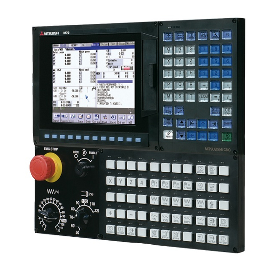
Mitsubishi Electric M700VS Series Manuals
Manuals and User Guides for Mitsubishi Electric M700VS Series. We have
1
Mitsubishi Electric M700VS Series manual available for free PDF download: Setup Manual
Mitsubishi Electric M700VS Series Setup Manual (664 pages)
Mitsubishi CNC
Brand:
Mitsubishi Electric
| Category:
Control Unit
| Size: 11.37 MB
Table of Contents
Table of Contents
14
1 Setup Outline
18
Device Configuration
19
Hardware Configuration
20
Flow of Initial Setup
21
2 Connecting and Setting the Hardware
22
Connecting and Setting the Drive Unit
23
Connecting with Servo Drive Unit
23
Connecting with MDS-D/DH Series
24
Connecting with MDS-DM Series
27
Connecting with MDS-SVJ3/SPJ3 Series
32
Setting up Without Connecting to the Motor/ Drive Unit
32
Setting the Rotary and DIP Switches
33
MDS-D/DH Series
33
MDS-DM Series
35
MDS-D-SVJ3/SPJ3 Series
37
Connecting the Batteries
38
Control Unit Battery
38
Servo Drive Unit Battery
39
Connecting and Setting the Remote I/O Unit
41
Outline of the Remote I/O Unit
41
Connection and Station No. Setting on Remote I/O Unit
43
Station No. Setting When Using Multiple Remote I/O Units
45
Device No. Assignment
49
Initializing the NC Internal Data (SRAM)
51
3 Setting up with M70/M700 SETUP INSTALLER
52
Compatible Data and Folder Configuration in the CF Card
54
Operation Procedure
56
Starting up M70/M700 SETUP INSTALLER
56
Installing Language Data
56
Installing Custom Data
58
Uninstalling Custom Data
59
Installing Custom Startup Screen
60
Uninstalling Custom Startup Screen
61
List of Error Messages
62
4 Setting the Parameters and Date/Time
64
Selecting the NC System Type
65
Setting on the System Setup Screen
66
Setting the Parameters for the Machine Specifications
70
Setting Date and Time
72
5 PLC Program Writing
74
Setting the Ethernet Communication
75
Connecting the Control Unit and a Personal Computer
76
Setting the Communication with GX Developer
77
Setting the Parameters on GX Developer
79
Writing a PLC Program with GX Developer
81
Writing a PLC Program to ROM with GX Developer
82
Setting the PLC Parameters
84
6 Confirming the Basic Operation
86
Checking Inputs/Outputs and Alarms
87
Confirming Manual Operation
88
Using the Manual Pulse Generator
88
Using JOG Feed
88
Servo Simplified Adjustment
89
First Measure against Vibration
89
Outline of MS Configurator
90
7 Setting the Position Detection System
92
Adjusting the Absolute Position Detection System
93
Marked Aligment Method I
94
Marked Point Alignment Method II
95
Other Setting Method
96
Machine End Stopper Method: Automatic Initialization
96
Machine End Stopper Method: Manual Initialization
99
Dog-Type
100
Precautions
101
Precautions Common for the Initilization Operation
101
Precautions Common for the Dogless-Type Absolute Position Detector
101
Adjustment of Reference Position Return in Relative Position Detection System
103
Dog-Type Reference Position Return
103
Dog-Type Reference Position Return Operation
103
Dog-Type Reference Position Return Adjustment Procedures
104
8 Setting the Tool Entry Prohibited Range
110
Stroke End (H/W OT)
111
Stored Stroke Limit (S/W OT)
112
Outline
112
Detailed Explanation
114
Stored Stroke Limit I
115
Stored Stroke Limit II
116
Stored Stroke Limit IB
118
Stored Stroke Limit IC
119
Movable Range During Inclined Axis Control
120
Stored Stroke Limit for Rotation Axis
121
Precautions
121
9 Confirming the Spindle Operation
122
In Manual Operation (with Manual Numerical Command)
123
In MDI Operation
124
Confirming the Rotation Speed
124
10 Setting the Deceleration Check
126
Function
127
Deceleration Check Method
128
Deceleration Check for Opposite Direction Movement Reversal
130
Parameter
131
Precautions
133
11 Data Backup and Restoration
134
All Backup
135
All Restoration
138
12 Hardware Replacement Methods
140
Durable Parts
141
Control Unit Battery
141
Display Unit Cooling Fan
143
Backlight
144
Fuse
146
Control Unit Protection Fuse
146
Operation Panel I/O Unit Protection Fuse
146
Front Memory Interface Card
147
Touch Panel Protective Sheet
148
Key Sheet
149
Control Unit
150
Installation on FCU7-DU120-11 (8.4-Type)
152
Installation on FCU7-DU140-11/31 (10.4-Type)
153
Installation on FCU7-DU140-31 (10.4-Type Touch Panel)
154
Calibration Setting and Confirmation
155
Display Unit
158
Keyboard Unit
159
Operation Panel I/O Unit
160
Compactflash (CF) Card
161
USB Memory
162
13 Cables
164
Precautions When Connecting/Disconnecting Cables
165
Precautions for Using Optical Communication Cable
168
Optical Communication Cable Outline and Parts
168
Precautions for Handling Optical Communication Cable
168
Precautions for Laying Optical Communication Cable
169
Appendix 1 Explanation of Parameters
170
Appendix 1.1 User Parameters
171
Appendix 1.2 Base Specifications Parameters
237
Appendix 1.3 Axis Specifications Parameters
306
Appendix 1.4 Servo Parameters
336
Appendix 1.5 Spindle Parameters
369
Appendix 1.6 Rotary Axis Configuration Parameters
425
Appendix 1.7 Machine Error Compensation Parameters
432
Appendix 1.8 PLC Constants
434
Appendix 1.9 Macro List
437
Appendix 1.10 Position Switches
447
Appendix 1.11 Open Parameters
461
Appendix 1.12 Device Open Parameters
462
Appendix 1.13 SRAM Open Parameters
463
Appendix 1.14 CC-Link Parameters
464
Appendix 1.15 Anshin-Net Parameters 2/ MTB-Net Parameters 2
476
Appendix 1.16 PLC Axis Indexing Parameters
489
Appendix 1.17 Screen Transition Chart
500
Appendix 1.18 Unit
501
Appendix 1.19 Inputting the Machine Parameters
501
Appendix 1.20 Machine Error Compensation (Function Details)
502
Appendix 1.20.1 Outline
502
Appendix 1.20.2 Setting Compensation Data
505
Appendix 1.20.3 Example in Using a Linear Axis as Base Axis
506
Appendix 1.20.4 Example in Using a Rotary Axis as Base Axis
510
Appendix 1.21 Position Switch (Function Details)
511
Appendix 1.21.1 Outline
511
Appendix 1.21.2 Setting and Operation Examples of Dog1 and Dog2
511
Appendix 1.21.3 Canceling the Position Switch
513
Appendix 1.22 Bit Selection Parameters #6449 to #6496
514
Appendix 2 Explanation of Alarms
516
Appendix 2.1 Operation Errors (M)
517
Appendix 2.2 Stop Codes (T)
533
Appendix 2.3 Servo/Spindle Alarms (S)
539
Appendix 2.3.1 Servo Errors (S01/S03/S04)
539
Appendix 2.3.2 Initial Parameter Errors (S02)
553
Appendix 2.3.3 Parameter Errors (S51)
555
Appendix 2.3.4 Servo Warnings (S52)
556
Appendix 2.4 MCP Alarms (Y)
559
Appendix 2.5 System Alarms (Z)
570
Appendix 2.6 Absolute Position Detection System Alarms (Z7*)
578
Appendix 2.7 Distance-Coded Reference Scale Errors (Z8*)
582
Appendix 2.8 Emergency Stop Alarms (EMG)
583
Appendix 2.9 Computer Link Errors (L)
586
Appendix 2.10 User PLC Alarms (U)
587
Appendix 2.11 Network Service Errors (N)
590
Appendix 2.12 Program Errors (P)
592
Appendix 2.13 Troubleshooting
623
Appendix 2.13.1 Troubleshooting for NC
623
Appendix 2.13.2 Troubleshooting for Drive System
624
Appendix 2.13.2.1 Troubleshooting at Power on
624
Appendix 2.13.2.2 Troubleshooting for each Alarm no
625
Appendix 2.13.2.3 Troubleshooting for each Warning no
652
Appendix 2.13.2.4 Parameter Numbers During Initial Parameter Error
655
Appendix 2.13.2.5 Troubleshooting the Spindle System When There Is no Alarm or Warning
656
Advertisement
Advertisement
Related Products
Mitsubishi Electric MELSEC iQ-R AnyWireASLINK
Mitsubishi Electric MELSEC-A Series
Mitsubishi Electric Melsec-QJ71E71-B5
Mitsubishi Electric Procon MOD-IP/50
Mitsubishi Electric MELDAS M64A
Mitsubishi Electric MELDAS M65S
Mitsubishi Electric MELSEC-Q62HLC
Mitsubishi Electric MELSEC-LD77MS2
Mitsubishi Electric MELSEC-LD77MS16
Mitsubishi Electric M700V Series
Mitsubishi Electric Categories
Air Conditioner
Controller
Projector
Inverter
Heat Pump
More Mitsubishi Electric Manuals
Login
Sign In
OR
Sign in with Facebook
Sign in with Google
Upload manual
Upload from disk
Upload from URL