Sign In
Upload
Manuals
Brands
Mircom Manuals
IP Access Controllers
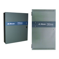
TX3-IP
Mircom TX3-IP Manuals
Manuals and User Guides for Mircom TX3-IP. We have
1
Mircom TX3-IP manual available for free PDF download: Installation Manual
Mircom TX3-IP Installation Manual (71 pages)
UL LISTED CARD ACCESS SYSTEMS
Brand:
Mircom
| Category:
IP Access Controllers
| Size: 4 MB
Table of Contents
Table of Contents
3
1 Welcome
6
Introducing the TX3-CX Card Access System
6
Applications
7
Installer Responsibilities
8
Network Setup
8
Figure 1 Basic Card Access System
9
Figure 2 Card Access System Using an RS-485 Network
9
Figure 4 Card Access System Using both Ethernet and RS-485 Networks
11
About this Manual
12
Contact Us
12
2 Configurable Features
13
Inputs
13
Correlations
14
Access Criteria
16
Timers
23
Schedules
24
Holidays
25
System Status
25
3 Mechanical Installation
26
Grounding the Card Access System
26
The TX3-CX-2-A Enclosure
27
Figure 5 Enclosure Dimensions for TX3-CX-2-A
27
The TX3-CX-4-A, TX3-CX-6-A, TX3-CX-8-A Enclosure
28
Mounting All Enclosures
29
Installing the TX3-PS24-5A Power Supply Enclosure for TX3-CX-4-A, TX3-CX-6-A, TX3-CX-8-A (Not Permitted in UL 294 Applications)
30
Figure 8 Inside the TX3-PS24-5A Enclosure
30
Figure 9 TX3-PS24-5A Voltage Selection Switch
31
Figure 10 TX3-PS24-5A Enclosure Dimensions
32
4 Setup of the Card Access Controller
33
Controller Board Description
33
Optional Components
35
Figure 11 Controller Board Connection Locations
35
Figure 12 IP Module Board Location
36
Figure 13 TX3-USB-AD Board Location
37
Figure 14 Controller Board Battery Wring
38
Figure 15 Modem Board Location
39
Power Supply Options
40
Figure 16 Modem Module Telephone Connectors
40
TX3-PS24-5A Power Supply (Not Permitted in UL 294 Applications)
41
Figure 17 Controller Board Power Supply
41
Figure 18 TX3-PS24-5A Terminal Block Wiring
42
Figure 19 RS-485 Wiring for TX3-CX-2-A
44
Figure 20 RS-485 Wiring for TX3-CX-4-A
44
USB Port
45
Inputs
45
Figure 21 RS--485 Wiring for TX3-CX-6-A
45
Figure 22 RS-485 Wiring for TX3-CX-8-A
45
Figure 23 Controller Board Input Terminals
46
Figure 24 Input Terminal Sample Connections
46
Figure 25 Input - Supervised for Open
48
Figure 26 Input - Supervised for Short
48
Outputs
49
Figure 27 Input - Supervised for Open and Short
49
Figure 28 Controller Output Terminal Sample Connections
51
Card Readers
52
Figure 29 Outputs 7 and 8 Sample Connections
52
Figure 30 Controller Board Card Reader Connectors
53
Setting DIP Switches SW2
54
Figure 31 Location of Jumpers JW1 to JW8 and Switches SW1
55
Setting Jumpers
56
Turning on the Controller
56
Updating Firmware
56
Beginning Configuration
57
5 RS-485 Addresses
59
6 TX3-CX-2-A Power Supply and Battery Calculations
62
Total Door Open Time Per Hour
62
Total Current for Door Lock
63
Battery Capacity Requirement
63
Advertisement
Advertisement
Related Products
Mircom TX3-TOUCH-S15B-WR
Mircom TX3-TOUCH-S15S-WR
Mircom TX3-CX-2-A
Mircom TX3-CX-4-A
Mircom TX3-CX-6-A
Mircom TX3-CX-8-A
Mircom TX3-USB-AD
Mircom TX3-CX-2K
Mircom TX3-CX-2K-A
Mircom TX3-CX-4K-A
Mircom Categories
Control Panel
Intercom System
Fire Alarms
Security System
Controller
More Mircom Manuals
Login
Sign In
OR
Sign in with Facebook
Sign in with Google
Upload manual
Upload from disk
Upload from URL