Sign In
Upload
Manuals
Brands
Mimaki Manuals
Printer
TextileJet Tx2-1600 Series
Mimaki TextileJet Tx2-1600 Series Manuals
Manuals and User Guides for Mimaki TextileJet Tx2-1600 Series. We have
3
Mimaki TextileJet Tx2-1600 Series manuals available for free PDF download: User And Maintenance Manual, Operation Manual
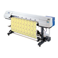
Mimaki TextileJet Tx2-1600 Series Operation Manual (166 pages)
Color Inkjet Printer
Brand:
Mimaki
| Category:
Printer
| Size: 4 MB
Table of Contents
Foreword
3
Disclaimer of Warranty
3
On this Operation Manual
3
FCC Statement (USA)
4
Interference to Televisions and Radios
4
Table of Contents
5
Features
10
How to Read this Operation Manual
12
Safety Symbols Used in this Manual
14
Structure of this Manual
15
For Safe Operation
16
Warnings in Use
16
Precautions in Use
16
Position of the Warning Label
17
Chapter 1 Setup
20
Installation of the Printer
20
Where to Install the Printer
20
Precautions in Installation
21
Checking the Accessories
22
Unpacking and Assembling
24
Assembling the Stand and the Device
24
Attaching Take-Up Auxiliary Bar
27
Attaching Loading Auxiliary Bar
27
Attaching Centering Sensor Unit
28
Attaching Loading Unit
28
Connecting Connectors and Cables
28
How to Remove the Stopper
29
Putting on the Maintenance Cover
29
Attach the Waste Ink Hoses
30
Attaching Slip Sheet Bar
30
Preparing the Waste Ink Tank
30
Configuration and Fnction
31
Front Face
31
Rear Face
32
Names and Function of the Parts under the Front Cover
33
Carriage
33
Capping Station
34
The Pinch Roller and Feed Roller
34
The Media Sensor
35
Head Hight Adjustment Rod and Adjustment Screw
35
Fablic Retainer
36
Ditch for Penetrated Ink and Platen Boards
37
About Other Setup
38
Attaching Lapel Bar
38
Attaching the Platen Boards
40
Changing Gap for Fablic Retainers
41
Installing IEEE1394 Output Driver
41
Connecting the Cables
42
Connecting the Interface Cable
42
Connecting the Power Cable
43
Switching ON/OFF the Power Supply
44
Turning the Power on
44
Turning the Power off
45
Front Cover and Maintenance Cover
46
Opening/Closing the Cover
46
Ink Cartridges
47
Types of Ink
47
Precautions in Handling the Ink Cartridge
47
Ink Stations
48
Display of Ink Type
49
Setting Ink Cartridges
50
Fabric for Printing
52
Types of Fablic that Can be Used
52
Precautions in Handling the Fabric
53
Limited Media
53
Before Setting the Fabric on the Printer
54
Adjusting the Head Height According to the Fablic [HEAD HEIGHT]
54
Points in Head Height Adjustment
57
Setting the Mating Sheet
58
Adjusting Parallelism of Loading Unit
58
Setting the Fabricto the Printer
59
Setting a Roll Fablic
59
Setting the Centering Sensor Position
63
Attaching Empty Fablic Core for Taking up
64
Removing Pinch Roller and Preventing Wrinkle of Fablic
65
Specifying the Scope of Printing on the Fabric Used (Effective Printing Area)
67
Origin Setting
68
Setting of an Origin
68
Moving the Printer
69
Chapter 2 How to Use the Basic Functions
72
Operation
72
Operation Panel
72
Functions of the JOG Keys
73
MENU Mode
73
Menu Tree
74
Setting the Display Language
76
Printing an Image from Saurce Data
77
Starting the Printer Operation
77
Information on Printing Data
78
Key Operation on REMOTE Mode
78
Correcting the Media Feed Rate During Printing [Feed Comp.]
79
Interrupting the Printing Operation
80
Checking Nozzle in Ink Firing Condition
81
Executing the Test Draw [TEST DRAW]
81
Checking the Test Patterns
81
If There Are Nozzle Clogging in Ink Firing Condition
82
Cleaning Ink Heads
82
Routine Maintenance
83
When the Device Is Left Unused for a Long Period of Time
83
Notes on Cleaning
83
Cleaning Ink at the Bottom of the Slider
83
Cleaning Wiper
83
Cleaning the Wiper Shaft
84
Maintenance for Frame Components
84
Cleaning Penetrated Ink
84
To Replenish Ink, Set a New Ink Cartridge in the Ink Station
85
Chapter 3 How to Use the Application Functions
88
Application Functions
88
Function Menu
88
Before Setting Printing Conditions in the Function Menu
89
Checking the Menu Mode
89
Registering Two or more Printing Conditions at a Time (Selecting a Type)
89
Changing the Type
90
Adjusting the Lapal Bar
91
Troubleshooting
92
After Setting the Fabric to be Printed
93
Correcting Error of Amount of Feed Depending on Fabric [MEDIA COMP.]
93
Setting Printing Conditions
94
Changing Printing Conditions on the Printer Side
94
Relationship between Image Quality and Printing Speed [QUALITY]
94
Printing Direction [DIRECTION]
95
Returning Speed up [RET. SPD UP]
96
Improving the Density of Ink Color [INK LAYERS]
97
Setting the Ink Drying Time [DRYING TIME]
98
Deciding the Priority of Settings by the Computer or the Plotter [PRIORITY]
99
Increasing (Decreasing) the Right and Left Margins of the Fabric [Rightmargin]/[Leftmargin]
101
Setting [Rightmargin]
101
Setting [Leftmargin]
102
When Using the Plotter in an Extremely Dusty or Dry Place [REFRESH]
103
Setting a Unit of Length Displayed on the LCD [MM/INCH]
104
Setting the Type of Ink to be Used [INK TYPE]
105
Setting up Auto-Cleaning Function [AUTO CLEAN]
106
Setting up Auto-Cleaning Function [AUTO CLEAN2]
107
Back Feed Setting for End of Printing [Endof PRINT]
109
Continuing Printing after [Ink Near End] [PRINT CONT.]
110
Preventing the Fabric Skew [CENTERING]
111
Enabling the Take-Up Unit [TAKE-UP]
112
Resetting Printing Conditions by Type [SETUP RESET]
113
Chapter 4 Maintenance Functions
115
Maintenance of the Printer
116
Function Menu [MAINTENANCE]
116
Before Starting Maintenance
117
Checking the Menu Mode
117
Invoking a Maintenance Function
117
Maintenance Functions
118
Drawing Setup Conditions [LIST]
118
Printing HEX Code of Printing Command [DATA DUMP]
119
Correcting the Dot Positions after Adjusting the Head Height [Printadjust]
120
Moving the Carriage to Clean the Station Interior [Carriageout]
122
If a Defective Printing Is Not Corrected Even after the Cleaning Function Is Executed
123
Periodical Cleaning of the Wiper
124
Notes on Handling the Wipers
124
When the Message [Replace Wiper] Is Displayed [WIPER EXCHG]
125
When the Message [Clean Wiper Shaft] Is Displayed
127
Cleaning the Nozzle [NOZZLE CLN]
128
Ink Discharge Way Cleaning [DRAIN WASH]
131
When Not in Use the Machine over the Long Term [STORAGE WSH]
133
Move the Carriage to the Left Maintenance Station [CARRIAGE]
137
Adjusting the Head Height When the Fabric Used Is Changed [HEAD HEIGHT]
138
Menu Displayed after the Ink Cartridge Is Installed [FILL up INK]
139
When Charging Ink Different from the One in Use [INK CHANGE]
140
Selecting Ink Head [USE HEAD]
143
Check the Stretch and Shrink of Fabric after the Printing [STRETCH CHK]
144
Displaying the Printer Information [INFORMATION]
146
Chapter 5 When Abnormal Conditions Are Encountered
147
Before Taking a Phenomenon as a Sign of Failure
148
The Printer Cannot be Energized
148
The Printer Cannot Perform Printing
148
Paper Jamming Arises/Fabric Is Soiled
149
If Image Quality Declines
150
White Lines/Thin Spots Are Obvious (in the Direction of Travel of the Head)
150
Displacement Is Observed between Outward and Inward Printing
150
The Respective Color Ink Injected by the Respective Color Heads Do Not Properly Overlap
150
Troubles for Which Error Message Are Given on the LCD
151
Warning Message
151
Error Messages
153
Appendix
157
Basic Specifications
158
Ink Specification
159
Optional Extras
160
Function Flow Chart
161
Advertisement
MIMAKI TextileJet Tx2-1600 Series Operation Manual (154 pages)
inkjet plotter
Brand:
MIMAKI
| Category:
Plotter
| Size: 5 MB
Table of Contents
Foreword
5
On this OPERATION Manual
5
Features
6
For Safe Operation
8
Pictorial Signs
8
Example of Pictorial Signs
8
Never Do the Following
9
Precautions in Use
10
Precautions in Installation
11
Table of Contents
12
How to Read this Operation Manual
17
Structure of this Manual
19
Chapter 1 Set-Up
19
Where to Install the Device
22
Checking the Accessories
23
Configuration and Function
25
Front Face
25
Rear Face
26
Names and Functions of the Parts under the Front Cover
27
Carriage
27
Capping Station
28
The Pinch Roller and Feed Roller
28
The Media Sensor
29
Head Hight Adjustment Rod and Adjustment Screw
30
Fablic Retainer
31
Ditch for Penetrated Ink and Platen Boards
32
Unpacking and Assembling
33
Assembling the Stand and the Device
33
Attaching Take-Up Auxiliary Bar
36
Attaching Loading Auxiliary Bar
36
Attaching Centering Sensor Unit
37
Attaching Loading Unit
37
Connecting Connectors and Cables
37
How to Remove the Stopper
38
Putting on the Maintenance Cover
38
Attach the Waste Ink Hoses
39
Attaching Slip Sheet Bar
39
Preparing the Waste Ink Tank
39
Lapel Bar
40
Limited Media
40
Attaching Lapel Bar
41
Connecting the Cables
42
Connecting the Interface Cable
42
For Windows 2000 (IEEE1394)
42
For Other Operating System (IEEE1284)
42
Connecting the Power Cable
43
Connect the Power Cable as Described below
43
Switching On/Off the Power Supply
44
Turning the Power on
44
Installing IEEE1394 Output Driver
45
Turning the Power off
45
Front Cover
46
Opening/Closing the Front Cover
46
Cautions During Operation
46
Ink Cartridges
47
Ink Stations
47
Relationships between Ink Station and Head Row
47
Types of Ink
49
IC Chip in Ink Cartridge
49
Precautions in Handling the Ink Cartridge
50
Display of Ink Type
50
Initial Settiing of Inks
51
Setting Ink Cartridges
52
Setting for 1-Way High-Speed Printing
52
Setting for 2-Way Multi Printing
53
To Replenish Ink, Set a New Ink Cartridge in the Ink Station
54
Fabric that Can be Used
55
Types of Fablic that Can be Used
55
Precautions in Handling the Fabric
56
Before Setting the Fablic on the Device
57
Adjusting the Head Height When the Fablic Used Is Changed [HEAD HEIGHT]
57
Before Setting the Fabric on the Device
57
Points in Head Height Adjustment
60
Setting the Fabric to the Plotter
61
Setting a Roll Fablic
61
Setting the Centering Sensor Position
65
Attaching Empty Fablic Core for Taking up
66
Removing Pinch Roller and Preventing Wrinkle of Fablic
67
Specifying the Scope of Printing on the FABRIC Used (Effective PRINTING Area)
69
Changing the Dead Space
69
Origin SETTING
70
Setting of an Origin
70
Other Settings
71
Attaching the Platen Boards
71
Switching the Winding Direction of the Fabric
71
Operating the Centering Manual Switch
72
Changing Gap for Fablic Retainers
73
Setting the Mating Sheet
74
Adjusting Parallelism of Loading Unit
74
Using Medium Cover
75
Moving the Plotter
76
Chapter 2 How to Use the Basic Functions
78
Operation
78
Operation Panel
78
Functions of the JOG Keys
79
MENU Mode
79
MENU Tree
80
Printing an Image from Source Data
82
Setting the Plotter Operationn
82
Interrupting the Printing Operation
83
After Completing the Printing Operation
83
Checking Faint or Missing Portions in Ink Discharge Condition
84
Executing the Test Draw [TEST DRAW]
84
Checking the Test Patterns
84
If There Are Faint or Missing Portions in Ink Discharge Condition
85
Cleaning Ink Heads
85
Routine Maintenance
86
When the Device Is Left Unused for a Long Period of Time
86
Notes on Cleaning
86
Cleaning Wiper
86
Cleaning Ink at the Bottom of the Slider
86
Cleaning the Wiper Shaft
87
Cleaning Penetrated Ink
87
Maintenance for Frame Components
87
Chapter 3 How to Use the Application Functions
90
Application Functions
90
Function Menu
90
Before Setting Printing Conditions in the Function Men
91
Checking the Menu Mode
91
Setting the Display Language
91
Registering Two or more Printing Conditions at a Time (Selecting a Type)
92
Changing the Type
92
Adjusting the Lapel Bar
93
Troubleshooting
94
After Setting the Fabric to be Plotted
95
Correcting Erroor of Amount of Feed Depending on Fabric [MEDIA Comp.]
95
Setting Printing Conditions
96
Changing Printing Conditions on the Device Side
96
Relationship between Image Quality and Printing Speed [QUALITY]
96
Extending the Resolution for High-Density Printing [EXTEND]
97
Printing Direction [DIRECTION]
98
Improving the Density of Ink Color [INK LAYERS]
99
SETTING the Ink Drying Time [DRYING TIME]
100
Deciding the Priority of Settings by the Computer or the Device [PRIORITY]
101
Increasing (Decreasing) the Right and Left Margins of the Fabric [Rightmargin] • [Leftmargin]
103
When Using the Device in an Extremely Dusty or Dry Place [REFRESH]
105
Setting a Unit of Length Displayed on the LCD [MM/INCH]
106
Setting the Type of Ink to be Used [INK TYPE]
107
Setting up Auto-Cleaning Function [AUTO Clean]
108
Continuing Printing after [Inknearend] [PRINT CONT.]
109
Correcting Amount of Cloth Feed While Checking Printing Condition [MEDIA COMP.]
110
Preventing Meandering of the Fablic [CENTERING]
111
Selecting Take-Up Method [TAKE-UP]
112
Using Optional Drying Device [DRYING DEV.]
113
Resetting Printing Conditions by Type [SETUP RESET]
114
Chapter 4 Maintenance Functions
116
Maintenance of the Device
116
FUNCTION Menu [MAINTENANCE]
116
Before Starting Maiantenance
117
Checking the Menu Mode
117
Invoking a Maintenance Function
117
Maintenance Functions
118
Drawing Setup Conditions [LIST]
118
Printing HEX Code of Printing Command [DATA DUMP]
119
Correcting the Dot Positions after Adjusting the Head Height [Printadjust]
120
Moving the Carriage to Clean the Station Interior [Carriageout]
122
If a Defective Printing IS Not Corrected Even after the Cleaning Function Is Executed
123
Periodical Cleaning of the Wiper
124
Notes on Handling the Wipers
124
When the Message [Replace Wiper] Is Displayed [WIPER EXCHG]
125
When the Message [W.SHAFT CLEANING] Is Displayed [W.SHAFT CLEANING]
128
Adjusting the Head Height When the Fabric Used Is Changed [Head Height]
129
Menu Displayed after the Ink Cartridge Is Installed [FILL up INK]
130
When Charging Ink Different from the One in Use [INK CHANGE]
130
Selecting Ink Head [USE HEAD]
132
Check the Stretch and Shrink of Fabric after the Printing [STRETCH CHECK]
133
Using the Ink with [INK Near END], [INK END] Display Continuously [REST ADJUST]
135
Chapter 5 When Abnormal Conditions Are Encountered
138
Before Taking a Phenomenon as a Sign of Failure
138
The Device Cannot be Energized
138
The Device Cannot Perform Printing
138
Paper Jamming Arises/Fabric Is Soiled
139
If Image Quality Declines
140
White Lines/Thin Spots Are Obvious (in the Direction of Travel of the Head)
140
Displacement Is Observed between Outward and Inward Printing
140
The Respective Color Ink Injected by the Respective Color Heads Do Not Properly Overlap
140
Troubles for Which Error Messages Are Given on the Lcd
141
Errors Accompanied by Warnings
141
Warning Messages Regarding Fabric Transportation
142
Error Messages
143
Appendix
147
Basic Specifications
148
Specification for Ink
150
Function Menu Structure
151
Position of the Warning Label
152
MIMAKI TextileJet Tx2-1600 Series User And Maintenance Manual (176 pages)
Brand:
MIMAKI
| Category:
Printer
| Size: 4 MB
Table of Contents
Table of Contents
4
Chapter 1 Overview of Maintenance
9
Cautions in Maintenance
10
How to Use this Maintenance Manual
11
Tools Required for Maintenance Works
11
Names of Parts
12
Front Face
12
Rear Face
13
Specifications
14
Cloth Media Handling Notes
17
Chapter 2 Explanation of Operation
19
Explanation of Electrical Components
20
Operations
20
Power Supply
22
Main PCB
22
1394 Pcb
26
I/F Connection PCB
26
HDC-4Head PCB (X2)
26
Io Pcb
28
Slider PCB
29
Linear Encoder PCB
31
2-1-10.The Keyboard PCB
31
Ink Sensor PCB
31
2-1-13.Take-Up Motor PCB
31
2-1-14.Centering PCB
31
2-1-15.Centering Sensor PCB
31
Ink System
32
Definitions
32
Brief Explanation of the Ink System
33
Parameters Related to the Ink System
36
Brief Explanation of Media Size Detection Control
37
Chapter 3 Troubleshooting
39
Troubles for Which Error Messages Are Given on the LCD
40
Error Messages and Corrective Measures
41
Error Messages for Troubles for Which Error Numbers Are Given on the LCD
41
Ink-Related Components and Other Components
44
Warning Messages Regarding Fabric Transportation
45
Troubles for Which Error Messages Are Not Given on the LCD
46
The Device will Not be Energized
46
The Device Fails to Perform Plotting
47
Plotting Failure
49
Abnormal Nozzle Discharge
49
Abnormal Ink Shot
49
Plotted Drawing Is out of Position
50
Print Is Not Sharp
50
Abnormal Print
51
Color of Print Is Pale
52
Ink-Filling Cannot be Performed
52
Plotted Dots or Lines Are Dirty
53
Stripes Are Always Drawn at the Time of Scanning
54
3-4-10.Black and White Stripes Appear from Side to Side
55
3-4-11.Dark and Light Images Occur at each Scan
55
3-4-12.The Media Feed Amount Is Not Equal on the Right and Left
56
Chapter 4 Maintenance Mode
57
Maintenance Items
58
Entering into the Maintenance Mode
59
Entering into the Maintenance Mode When Actuating the Plotter
59
Entering into the Maintenance Mode by System Parameters
60
Menu of #ADJUST
61
Printadjust2
61
Head Adjust
67
Head Wash
69
Select Cleaning
71
Replace Counter
73
Default Set
75
Capping
76
Ink Setup
77
Head ID
78
4-3-10.Adjust Edge
79
4-3-11.500Mm SQUARE
81
4-3-12.Set Quality
83
4-3-13.Media Comp2
84
TEST Items
86
Check Pattern
86
Parameter Draw
93
All Pattern
94
Servo
95
Y Servo
96
Xy Servo
97
Action Test
98
Sensor Test
99
Keyboard Test
102
4-4-10.Display Test
103
4-4-11.Lcd Test
104
4-4-12.Pump Motor
105
4-4-13.Timer Check
106
4-4-14.Memory Check
107
4-4-15.Skew Check
111
4-4-16.Temp Check
112
4-4-17.Encoder Check
113
PARAMATER Items
116
System Parameter
116
Ink Parameter
119
Maintenance Parameter
119
Servo Parameter
119
Adjustment Parameter
119
Information Parameter
119
Uploading and Downloading Parameters
120
UPLOAD (Plotter >>> Computer)
120
DOWNLOAD (Computer >>> Plotter)
121
Updating the Firmware
123
The Firmware in this Unit
123
Main Unit Side Firmware Version Updating File
123
Interface Side Firmware Version Updating File
124
Checking the Version Updating File
124
Updating Procedure
125
Maintenance Menu Tree
127
Chapter 5 Disassembling / Assembling Procedure
129
Disassembly and Assembly
130
Front Cover Assy., y Cover, SR Cover, YR Cover and Right Cover
130
F Cover L/R, Platen Cover, and Paper Sensor R Assy
132
X-Motor Assy
133
Paper Feed Roller (Do Not Disassemble)
134
Keyboard Assy. and IO PCB Assy
134
Slowdown Belt (3 Type), XM Assy, X-Pulley, Driving Roller Pulley
136
Joint Shaft Pulley
136
Friction Roller
138
Y-Motor Assy., S3M Belt 160, Clean Toothed Belt
139
Head Cover, Slider PCB and Linear Encoder PCB Assy. / Scale
140
5-1-10.Print Head
142
5-1-11.Main FPC Cable Assy
144
5-1-12.Cloth Width Sensor PCB Assy
146
5-1-13.Cap Assy
147
Station Sensor Assy., Capping Sensor Assy. and Wipersensor Assy
148
5-1-15.Ink Supply Tube (Inside Diameter: Ø2Mm)
150
And Power PCB
151
5-1-17.Centering Motor Assy
153
ID Contact PCB Assy, Cartridge Sensor, I/C, y
154
Chapter 6 Adjustment
155
Adjusting Item List
156
Adjusting Item
157
Adjustment of the Station Position
157
Adjustment of the Linear Sensor PCB Assy Height
162
Adjustment of the Y-Motor Belt Tension
163
Adjustment of the X-Motor Belt Tension
164
Adjustment of the Head (Head Angle / Head Stagger)
165
Adjustment of the X Slowdown Belt (100 S3M 459)
169
Adjustment of the X Slowdown Belt (100 S3M 243)
170
Adjustment of the Friction Roller Position
171
Adjustment of the Right and Left Edge Position
172
And the Feed Torque Limiter
173
Advertisement
Advertisement
Related Products
MIMAKI TX500-1800DS
MIMAKI Tx400-1800D series
MIMAKI tx300p
MIMAKI Tx500P-3200DS
MIMAKI TX300P-1800
MIMAKI Tx300P-1800B
Mimaki Tx300P-1800MkII
MIMAKI TxF150-75
MIMAKI TxF300-75
MIMAKI TxF300-1600
Mimaki Categories
Printer
Plotter
Printer Accessories
Cutter
Industrial Equipment
More Mimaki Manuals
Login
Sign In
OR
Sign in with Facebook
Sign in with Google
Upload manual
Upload from disk
Upload from URL