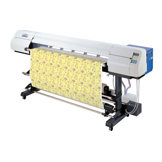
MIMAKI Tx2-1600 Operation Manual
Inkjet plotter
Hide thumbs
Also See for Tx2-1600:
- Operation manual (166 pages) ,
- User and maintenance manual (176 pages)
Table of Contents
Advertisement
Quick Links
Advertisement
Table of Contents

Related Manuals for MIMAKI Tx2-1600


Summary of Contents for MIMAKI Tx2-1600
- Page 1 OPERATION MANUAL MIMAKI ENGINEERING CO., LTD. TKB Gotenyama Building, 5-9-41, Kitashinagawa, Shinagawa-ku, Tokyo 141-0001, Japan Phone: +81-3-5420-8671 Fax: +81-3-5420-8687 URL: http: // www.mimaki. co. jp / E-mail: traiding@mimaki.co.jp D200595...
- Page 3 ING CO., LTD. has been informed of the possible risk of such damages in prior. For example, MIMAKI shall not be liable to any damage to fabric (works) due to the use of the product or any indirect damage that is caused by a product that is manufactured the fabric.
- Page 4 • In the case where MIMAKI-recommended cable is not used for con- nection of this device, limits provided by FCC rules can be exceeded. To prevent this, use of MIMAKI-recommended cable is essential for the connection of this device.
-
Page 5: Foreword
FOREWORD Thank you for purchasing MIMAKI Tx2-1600 color inkjet plotter for textile. Model Tx2-1600 is a color inkjet plotter for printing on fabric with eight different colors at high speeds. Read this manual carefully and make the most effective use of your plotter. -
Page 6: Features
Reactive dye ink : Suitable for wool, silk in addition to cotton, rayon, etc. • When using any type of ink, be sure to perform the pre-processing and post- processing recommended by MIMAKI for the fabric used. APPLICABILITY OF FABRICS UP TO 7 MM IN THICKNESS Even thick fabric, such as boards, can be used. - Page 7 HIGH-SPEED INTERFACE The "IEEE 1394" interface allows for high-speed data reception from the computer. TAKE-UP DEVICE FOR PRINTING ON A LONG FABRIC Since the take-up device that is interlocked with the device winds up the fabric as it is plotted on, even a long mefabric c be used.
-
Page 8: For Safe Operation
FOR SAFE OPERATION PICTORIAL SIGNS Pictorial signs are used in this Instruction Manual for safe operation of and in prevention of damages to the device. Pictorial signs and their meanings are given below. Read and fully understand before reading the text. •... -
Page 9: Never Do The Following
• Never refill the ink cartridge do so. with ink. • MIMAKI assumes no Roll fabric responsibility for malfunction • Roll fabric is heavy. Be careful not caused by using the device to drop it. -
Page 10: Precautions In Use
There are some parts which before starting printing. If the must be replaced by service device performs printing without men after Tx2-1600 are in use locked, the device can move out for 5000 hours from 3000 hours. of position. Therefore, we would like to... -
Page 11: Precautions In Installation
CAUTION Ink cartridges • If the ink cartridge is moved from • Be sure to store ink cartridges a cold place to a warm place, in a cold and dark place. leave it in the room temperature • Never replenishes the ink for three hours or more before cartridge with ink. -
Page 12: Table Of Contents
TBLE OF CONTENTS FOREWORD ......................... i On This OPERATION Manual ......................i FEATURES ........................ii FOR SAFE OPERATION .................... iv Pictorial signs ........................... iv Example of pictorial signs ........................ iv Never Do the Following ........................v Precautions in use ........................... vi Precautions in installation ....................... - Page 13 CONNECTING THE CABLES................1.22 Connecting the interface cable ....................1.22 For Windows 2000 (IEEE1394) ....................1.22 For other operating system (IEEE1284) ..................1.22 CONNECTING THE POWER CABLE ..............1.23 Connect the power cable as described below ................1.23 SWITCHING ON/OFF THE POWER SUPPLY............1.24 Turning the power on ........................
- Page 14 Changing gap for fablic retainers ....................1.53 Setting the mating sheet ......................1.54 Adjusting parallelism of loading unit .................... 1.54 Using medium cover ........................1.55 Moving the plotter ........................1.56 CHAPTER 2 HOW TO USE THE BASIC FUNCTIONS OPERATION ......................2.2 Operation panel ..........................
- Page 15 Relationship between image quality and printing speed [QUALITY] ..........3.8 Extending the resolution for high-density printing [EXTEND] ............3.9 Printing direction [DIRECTION] ....................3.10 Improving the deNSITY of ink color [INK LAYERS] ..............3.11 SETTING the ink drying time [DRYING TIME] ................3.12 Deciding the priority of settings by the computer OR the device [PRIORITY] ......
- Page 16 IF IMAGE QUALITY DECLINES ................5.4 White lines/thin spots are obvious (In the direction of travel of the head) ........5.4 Displacement is observed between outward and inward printing ..........5.4 The respective color ink injected by the respective color heads do not properly overlap ....5.4 TROUBLES FOR WHICH ERROR MESSAGES ARE GIVEN ON THE LCD ..
-
Page 17: How To Read This Operation Manual
HOW TO READ THIS OPERATION MANUAL HOW TO READ THIS OPERATION MANUAL The titlle in each chapter are provided. Notes to sentences, caution on device The item to select operation, and hints for from the setting effective use of the menu before each device are given. - Page 18 Display on the LCD and Indication of the Keys In this instruction manual, the characters displayed on the LCD of the operation panel and the keys used to operate the device are explained, together with the operation procedure. (see page 2.2) Operate the device while confirming the display on the LCD.
-
Page 19: Structure Of This Manual
STRUCTURE OF THIS MANUAL CHAPTER 1 SET-UP This chapter describes the procedures for unpacking and assembling the device, and for setting up the device such as setting inks and fabric. CHAPTER 2 HOW TO USE THE BASIC FUNCTIONS This chapter describes the basic operations of the device, from the begin ning to the end of printing. - Page 20 - xvi -...
- Page 21 CHAPTER 1 SET-UP This chapter describes the procedures for unpacking and assembling the device, and for setting up device such as setting inks and fabric. Table of contents WHERE TO INSTALL THE DEVICE ..............1.2 CHECKING THE ACCESSORIES ............... 1.3 CONFIGURATION AND FUNCTION ..............
-
Page 22: Where To Install The Device
The place of installation must have space required not only for the device itself but also for printing operation. Length Width Height Gross weight 2750 mm 750 mm 1350 mm About 170 Kg 500 mm 500 mm 3750 mm ( Tx2-1600 ) - 1.2 -... -
Page 23: Checking The Accessories
CHECKING THE ACCESSORIES Open the packing box and check the components in it. If you find any missing accessory or damaged one, please contact your local dealer. • It varies according to your order for Ink Cartridge and the additional accesories. - Page 24 Printing film (for adjustment of the device) Slip sheet bar Centering sensor unit Phillips screwdriver Power cable Hexagonal wrench (L) Ink Cartridge (8 x 2) Device Driver Grouding adapter M4 cap bolt M8 cap bolt Lapel bar x 3 for fitting the take-up device (4 pcs) for fitting the main unit (24 pcs) - 1.4 -...
-
Page 25: Configuration And Function
CONFIGURATION AND FUNCTION Front face Name Function Front cover It is opened when setting fabric or taking a corrective measure against a fabric jam. Parallel connector Bi-directional parallel interface connector (complies with IEEE1284) IEEE1394 connector 400Mbps interface connector compatible with IEEE1394. AC inlet The power cable is connected to the AC inlet. -
Page 26: Rear Face
Rear face Name Function F-row ink station This station houses up to eight ink cartridges. Clamp lever It is made to go up-down the pinch roller for holding fabric. Centering sensor unit This sensor detects the fabric edge and optical axis so that the fabric be fed straight. -
Page 27: Names And Functions Of The Parts Under The Front Cover
NAMES AND FUNCTIONS OF THE PARTS UNDER THE FRONT COVER Under the front cover, there are the carriage, capping station, etc. necessary for printing operation. The mechanisms provided under the front cover are explained below. Carriage The carriage is provided with print heads for printing, etc. It is also provided with a head height adjustment screw for adjusting the head height according to the thickness of the fabric used. -
Page 28: Capping Station
Capping station The capping station consists of ink caps, wipers for cleaning the heads, etc. Ink Cap : It covers the nozzles of print head to prevent from drying up. Wiper It is used to clean the head nozzles. Wiper Ink Cap The pinch roller and feed roller This device retains a fabric with the pinch roller and the feed roller. -
Page 29: The Media Sensor
The media sensor The media sensors detects the presence of the fabric and the end of fabric. There is one media sensors on the platen. • If a transparent fabric or a fabric whose reverse side is colored in black, the sheet sensors may fail to detect the sheet. -
Page 30: Head Hight Adjustment Rod And Adjustment Screw
Head hight adjustment rod and adjustment screw When a fabric is set for the first time or replacing a fabric in different thickness, it is necessary to adjust the height of the head. • If the plotter is operated without adjusting the head height, the head may get caught on the fabric, causing damage to the heads. -
Page 31: Fablic Retainer
Fablic retainer If the edge of the fabric is curled or it is raised, it may be caught by the head or inferior ink dis- charge may occur. To avoid this trouble, use the fabric pressers. • The fablic retainer also act as a detection board which detects the printing width. -
Page 32: Ditch For Penetrated Ink And Platen Boards
Ditch for penetrated ink and platen boards Printing on a coarse-textured fablic may cause ink to penetrate the fablic. If the fabric runs out in this condition, it may be stained by the ink on the platen. The ditch for penetrated ink is provided to avoid this trouble. •... -
Page 33: Unpacking And Assembling
UNPACKING AND ASSEMBLING Assembling the stand and the device • The pack of the plotter is as heavy as approximately 250 kg. Perform the assembly work by at least four persons to ensure safety. • Exercise added care not to drop the main unit on your feet. STEP 1. - Page 34 3. Take the stands out of the package. Direct the stands so that round tapped holes for the screws are faced outside. Set up each stand with the side having a groove for fitting the stay coming inside. 4. Attach the take-up device to the leg. Put the take-up device on the leg and then temporarily secure it using the supplied screws and screw driver.
- Page 35 6. Holding both ends of the main unit with four persons. Hold up the device at the pedestal support bars. 7. Place the main unit on the stands while exer- cising care not to allow hands to be caught between them. Set the device on the stand at the position where the screw holes in the device align with the screw holes in the tops of the stands.
-
Page 36: Attaching Take-Up Auxiliary Bar
9. Connect the cable of take-up device into the connector located at the left bottom of the main unit. Attaching take-up auxiliary bar Align the screw hole of the take-up auxiliary bar with the screw hole on the front face of the stand, then fasten the screws. -
Page 37: Attaching Centering Sensor Unit
Attaching centering sensor unit Align the screw hole of the centering sensor unit with the screw hole of the run-out auxiliary bar, then fasten the screws. Attaching loading unit Align the screw hole of the run-out device with the screw hole of the stand, then fasten the screws. -
Page 38: How To Remove The Stopper
How to remove the stopper 1. Loosen a screw fastening the Head Stopper, using Driver. 2. Remove the Head Stopper as shown on the ② Photo. ① Putting on the maintenance cover 1. Put on the maintenance cover. Operation panel 2. -
Page 39: Attach The Waste Ink Hoses
Attach the waste ink hoses. 1. Set the waste ink hoses. 2. Secure the supplied hose retainer with screws and then attach the waste ink hoses to the device unit. Attaching slip sheet bar Put the slip sheet on the hanger on the inner side of the stand. -
Page 40: Lapel Bar
LAPEL BAR The lapel bar is used to stabilize the medium tension of the run-out side. If the media tension of the roll-out side becomes unstable, printing is adversely affected (vertical black or white lines occurs). If the tension is too high, the media becomes susceptible to vertical wrinkles which may cause black or white lines. -
Page 41: Attaching Lapel Bar
Attaching lapel bar • Please reset the lapel bar properly if it’s shaky up and down. • Please adjust the attachment of the side plate assembly if the lapel bar does not rotates smoothly. 1. Loosen the thumb-screw inside the left and right plates. -
Page 42: Connecting The Cables
When operating system is other than Windows 2000, use an IEEE1284 interface cable to connect the computer and the plotter. Configuration of connector (IEEE1284) • If the customer uses Windows 2000 and the computer is not provided with an IEEE1394 board, contact your nearest RIP provider or MIMAKI sales office. - 1.22 -... -
Page 43: Connecting The Power Cable
CONNECTING THE POWER CABLE Connect the power cable as described below Connect the power cable to the receptacle of the following specifications. • Voltage : AC 100 - 240 V ±10% • Frequency : 50/60 Hz ±1% • Capacity : 4.5 A or more (450 W or more) •... -
Page 44: Switching On/Off The Power Supply
SWITCHING ON/OFF THE POWER SUPPLY After setting up the device, switch on and off the power as described below. Turning the power on STEP 1. Turn on the power to the computer, etc. that are connected to the device. 2. Turn on the power to the device. Tilt the power switch toward the “... -
Page 45: Installing Ieee1394 Output Driver
Installing IEEE1394 output driver When connecting the device using the host computer and IEEE1394 interface, it may be necessary to install the IEEE1394 output driver and TXLink V2. • For the installation procedure, refer to the contents of the TXLink V2 CD- ROM supplied with the device. -
Page 46: Front Cover
FRONT COVER Opening/closing the front cover Do not open the front cover while the device is in operation. If you open the front cover during printing, the carriage will stop for safety, reselting in abortion of printing. In this case, re-start the device and computer following the procedure described below. •... -
Page 47: Ink Cartridges
INK CARTRIDGES Ink stations As viewed from the front of the device, the ink station on the right side is called the “right ink station” and the ink station on the left side is called the “left ink station.” F-row ink station Capable of housing eight ink cartridges, this ink station supplies... - Page 48 Set the ink cartridge referencing the following table. Acid dye ink Disperse dye ink Reactive dye ink (For direct print and transfer) (For transfer) GRAY (SPC-0268GR) GRAY (SPC-0269GR) GRAY (SPC-0270GR) BLACK (SPC-0268K) BLACK (SPC-0269K) BLACK (SPC-0270K) CYAN( SPC-0268C) CYAN (SPC-0269C) CYAN (SPC-0270C) LIGHT CYAN (SPC-0268LC) LIGHT CYAN (SPC-0269LC)
-
Page 49: Types Of Ink
• Be sure to use MIMAKI Geruine Ink cartridges. Even during the warranty period, failures occurring through the use of non- MIMAKI genuine ink will be handled on a fee basis. Acid dye ink [Acid] : Suitable for wool, silk, and other animal fibers and nylon. -
Page 50: Precautions In Handling The Ink Cartridge
• Do not shake the ink cartridge violently. Shaking or turning it roughly can cause leakage of ink. • Never refill the ink cartridge with ink. This might cause a trouble.Mimaki assumes no responsibility for any damage caused by using replenished ink cartridges. -
Page 51: Initial Settiing Of Inks
INITIAL SETTIING OF INKS When using the plotter for the first time or changing ink set to another, it is necessary to set ink type. Use the following procedure to install the ink cartridges. STEP 1. Turn the power on. INK TYPE After the initial operation, the device displays the type of ink R : Acid... -
Page 52: Setting Ink Cartridges
SETTING INK CARTRIDGES Setting for 1-way high-speed printing New piezo electric heads, the staggered-layout print head provides more attractive, faster printing, and allows ultra high-precisions 8-head 1-way printing. R-row ink station F-row ink station Set the left and right ink cartridge cases with ink cartridges of the same types and same colors. •... -
Page 53: Setting For 2-Way Multi Printing
Setting for 2-way multi printing Alternatively, using two sets of three heads in 2-way printing mode, each with different inks, gives you the functionality of two 8-color plotters in a single unit. • Before starting the printing operation, select the ink type to be used (See page 1.31). -
Page 54: To Replenish Ink, Set A New Ink Cartridge In The Ink Station
TO REPLENISH INK, SET A NEW INK CARTRIDGE IN THE INK STATION Setting a new ink cartridge is required when the ink is to be replenished or when the device becomes the following condition. If the ink cartridge is not replaced, the carriage stops during the printing operation when the ink runs out. -
Page 55: Fabric That Can Be Used
FABRIC THAT CAN BE USED This section describes the types of fabric that can be used with the device and the method of setting the media used. Types of fablic that can be used The types of fabric that can be used with this plotter “Roll” and “Leaf” fabric are cut sheet media. However, because leaf fabric is handled in the same manner as roll fabric, be careful about the setting position of leaf fabric. -
Page 56: Precautions In Handling The Fabric
Carefully observe the following when handling the fabric. • Pre-processing of fabric Use pre-processed fabrics recommended by MIMAKI. Fabrics with MIMAKI recommended pre-treatment. • Fabric thickness When setting the fabric used, be sure to adjust the head height. Other wise, the fabric and/ or the head can be damaged. -
Page 57: Before Setting The Fablic On The Device
BEFORE SETTING THE FABLIC ON THE DEVICE Adjusting the head height when the fablic used is changed [HEAD HEIGHT] When changing to the fabric of other kinds, it is necessary to adjust the head height according to the thickness of the new fabric. If the height of the head is inappropriate to the thickness of the fabric, the plotter cannot work properly. - Page 58 4. Push the JOG keys[ ] and [ ] until the LCD MAINTENANCE HEAD HEIGHT < ent > gives the indication [HEAD HEIGHT]. 5. Push the [ENTER] key twice. MAINTENANCE The carriage will come out of the capping station. CARRIAGEout : ent 6.
- Page 59 3. Turn the head height adjustment screw in the direction shown and move the head downward. With the head height adjustment rod kept pushed, lower the head till the tip of the rod makes contact with the surface of the fabric. Tip of the head height adjustment rod Fabric...
-
Page 60: Points In Head Height Adjustment
Points in head height adjustment • When the head height is so adjusted that the tip of the head height adjust- ment rod just makes contact with the surface of the fabric, the distance between the head and the printing surface of the fabric becomes optimum. •... -
Page 61: Setting The Fabric To The Plotter
SETTING THE FABRIC TO THE PLOTTER The fabric that can be used are roll and leaf fabric. Leaf fabric is handled in the same manner as roll fabric for printing. When using leaf paper for setup list printing, for example, be careful about the setting position. Setting a roll fablic The procedure for setting roll fabric is described below. - Page 62 3. Loosen the screw of the right-hand roll holder. Adjust the roll holder position to the width of the roll fabric. 4. Insert the right-hand roll holder into the core of the roll fabric. When the roll holder have been inserted all the way into the fabric core, secure it with the screw.
- Page 63 6. Pull out the fabric from the rear side of the plotter to the height of the Y cover. 7. Insert the leading edge of the fabric between the driver roller and pinch roller. Be sure to lead the fabric outside the shaft of the centering sensor.
- Page 64 9. Pull out the leading edge of the fabric from the front face of the plotter. • Open the front cover, move up the clamp level while holding the leading edge of the fabric with your hand, then pull out the fabric. 10.
-
Page 65: Setting The Centering Sensor Position
Setting the centering sensor position After setting the fabric to the plotter, please set the centering sensor position. • When adjusting the optical axis after the cloth width detection, the beep will not sound. Please make sure to adjust the centering sensor position before detecting the cloth width. -
Page 66: Attaching Empty Fablic Core For Taking Up
Attaching empty fablic core for taking up To take up the fabric after printing, attach an empty fabric core to the take-up device. 1. Close the front cover to allow detection of the ROLL< >LEAF roll fabric. 2. Push the JOG key [ ] and [ ] to move the <<... -
Page 67: Removing Pinch Roller And Preventing Wrinkle Of Fablic
Removing pinch roller and preventing wrinkle of fablic • If either edge of the fabric stretches longer than the center or if an edge of the fabric is thickened because of gumming processing to prevent fray, slack may occur easily. In this case, remove the pinch rollers at both ends of the fabric. - Page 68 4. To prevent fall-off or loss of the hand screws, lightly fasten them. • If the lengths of the fabrics at the left and right pinch rollers removed are different remarkably, reset the fabric. (Perform the operation of "SETTING THE ROLL", from step5. on page 1.42 to page 1.46 again.) - 1.48 -...
-
Page 69: Specifying The Scope Of Printing On The Fabric Used (Effective Printing Area)
SPECIFYING THE SCOPE OF PRINTING ON THE FABRIC USED (EF- FECTIVE PRINTING AREA) The plotter has an area which cannot perform printing, due to mechanical reasons. This area is called “dead space.” The effective printing area is obtained by excluding the dead space from the printing fabric. dead space dead space Default : 10 mm... -
Page 70: Origin Setting
ORIGIN SETTING Establish an origin in terms of data on fabric loaded on the plotter. Place the fabric and cause the plotter to detect the fabric, the origin is automatically established at the location shown in the illus- tration given below. Roll fabric Fabric Retainer Origin... -
Page 71: Other Settings
OTHER SETTINGS Attaching the platen boards Attach the platen boards when using a fabric without ink penetration. Set the attachment position and orientation of the platen boards in three steps according to the degree of ink penetration. (See page 1.12) The F cover is open. -
Page 72: Operating The Centering Manual Switch
Operating the centering manual switch The centering manual switch is operated to set a new roll. It allows the fabric to run out straight, minimizing the fluctuation of the fabric edge to the left and right. STEP 1. Pull up the clamp lever at the front of the de- vice. -
Page 73: Changing Gap For Fablic Retainers
Changing gap for fablic retainers • When the thickness of the fabric used is 1.5mm or less, use it with the stainless plate moved down to the bottom of the long hole and then se- cured with a screw. • When the thickness of the fabric used is 1.5mm to 5.5mm, use it with the stainless plate moved up to the top of the long hole and then secured with a screw. -
Page 74: Setting The Mating Sheet
Setting the mating sheet The mating sheet is used to prevent ink penetration of the fabric which is not dried after printing. 1. Set the fabric core of the slip sheet to the slip sheet bar hanger. Adjusting parallelism of loading unit If the parallelism of the loading unit is remarkably broken, the fabric deviation or wrinkle may occur. -
Page 75: Using Medium Cover
3. Clamp the fabric again and then start printing. • Note that fabric deviation may occur if the width is adjusted too large. Using medium cover The medium cover is used to prevent the fabric from being caught by the roll holder when the take- up device is used with the "slack method."... -
Page 76: Moving The Plotter
Moving the plotter The method of moving the assembled unit to the place of installation, etc. is explained below. When moving the plotter, unlock the caster stoppers. • When moving the device, take care not to apply excessive shock to it. •... - Page 77 CHAPTER 2 HOW TO USE THE BASIC FUNCTIONS This chapter describes the basic operations of the device, from the be- ginning to the end of printing. Before using the application functions, understand how to use the basic functions of the keys on the operation panel and the modes in which the menus are displayed on the LCD.
-
Page 78: Operation
OPERATION This section describes the operation panel that is used to operate the device and the menus from which to choose the desired item. Operation panel The operation panel that is used to operate the device and a method of maintenance of the device after operation, etc. -
Page 79: Functions Of The Jog Keys
Functions of the JOG keys Each of the JOG keys varies in function according to the time at which it is used. The functions of the JOG keys are explained below. When inputting a Before the detection After the detection When selecting a choice selected among of a sheet... -
Page 80: Menu Tree
MENU tree The operation of device and printing conditions are set by pushing the appropriate operation keys, selecting the desired setting item and setting detailed conditions. In order to operate the device properly, it is necessary to understand the structure of the menu tree (See page Appendix.5). - Page 81 Some menus simply list items which do not require the operator to set any of them. In this case, the operator is required to select the content to be displayed on the LCD. [Operation key] DISPLAY The operation mode is displayed. <...
-
Page 82: Printing An Image From Source Data
PRINTING AN IMAGE FROM SOURCE DATA Setting the plotter operationN This section describes the basic operation of the device. Printing conditions can be set on the device side. In this section, however, the method of printing an image from data that has been set on the computer side and transmitted to the device is explained. For the method of setting printing conditions on the device side, see Chapter 3 "How to Use the Application Functions."... -
Page 83: Interrupting The Printing Operation
Interrupting the printing operation To interrupt the printing operation that has been started, stop the carriage and erase (the receive data) from the device. STEP 1. Push the [REMOTE] key to stop the printing << LOCAL >> operation. width : 1272mm 2. -
Page 84: Checking Faint Or Missing Portions In Ink Discharge Condition
CHECKING FAINT OR MISSING PORTIONS IN INK DISCHARGE CONDITION Executing the test draw [TEST DRAW] In prior to the actual printing or after the execution of the cleaning function, a test pattern is plotted to check whether the finished test pattern has blurred and missing lines on test pattern) •... -
Page 85: If There Are Faint Or Missing Portions In Ink Discharge Condition
IF THERE ARE FAINT OR MISSING PORTIONS IN INK DISCHARGE CONDITION Cleaning ink heads If a test pattern plotted is defective, execute the cleaning function to clean the associated ink head. After cleaning the ink head, make the device plot a test pattern again. If the test pattern is defective too, re-clean the ink head. -
Page 86: Routine Maintenance
ROUTINE MAINTENANCE Be sure to conduct maintenance works for the device when necessary or periodically so as to use the device for a long time while keeping its printing accuracy. When the device is left unused for a long period of time •... -
Page 87: Cleaning The Wiper Shaft
Cleaning the wiper shaft The dirty wiper shaft may cause the wiper malfunction and resulting an error display. Cleaning penetrated ink When printing is made on a thin cloth, the ditch for penetrated ink may be stained by penetrated ink. In this case, clean the ditch with water. - Page 88 - 2.12 -...
- Page 89 CHAPTER 3 HOW TO USE THE APPLICATION FUNCTIONS After you have mastered the operations described in Chapter 2 “How to Use the Basic Functions,” you should learn how to use the application functions whereby you can set printing conditions on the device side and put the device into operation.
-
Page 90: Application Functions
APPLICATION FUNCTIONS The application functions make it possible to modify the printing conditions that have been set for source data received from the computer. The [FUNCTION] key is used to set up the application functions. FUNCTION MENU Of the menus that are provided for setting printing conditions for the device, the menu for setting up the device functions is called the function menu. -
Page 91: Before Setting Printing Conditions In The Function Men
BEFORE SETTING PRINTING CONDITIONS IN THE FUNCTION MEN The basic operation of the function menu for setting individual printing conditions is explained below. Set the individual printing conditions in the function menu after performing the following three operations. 1. Check that the menu mode is the LOCAL mode. 2. -
Page 92: Registering Two Or More Printing Conditions At A Time (Selecting A Type)
Registering Two or More Printing Conditions at a Time (Selecting a Type) Register a sequence of printing conditions set in the FUNCTION mode in the memory of the device. By allocating the the sequence of printing conditions to any of Types 1 through 4, it is possible to reuse the same printing conditions registered by type. -
Page 93: Adjusting The Lapel Bar
ADJUSTING THE LAPEL BAR Diverse types of media are used for inkjet printers: different raw materials including natural materi- als, synthesized materials, etc. and materials with different manufacturing processes including textile fabric, knit fabric, etc. In addition, even for the same medium, the elasticity characteristic changes according to the difference in pre-treatment, etc. -
Page 94: Troubleshooting
Troubleshooting The following describes general troubleshooting. With some corrective mesures, problems may not be solved depending on the medium used. If a problem cannot be solved after performing test printing several times, stop using the plotter. Plobrems Corrective measures Remarks Black lines occur. -
Page 95: After Setting The Fabric To Be Plotted
AFTER SETTING THE FABRIC TO BE PLOTTED Correcting erroor of amount of feed depending on fabric [MEDIA COmp.] The device plots an image on the fabric while feeding it forward little by little. When the thickness of the fabric changes, the optimum feed rate changes accordingly. If this occurs, the device may not plot a clear image (e.g., unwanted stripes may appear on the image). -
Page 96: Setting Printing Conditions
SETTING PRINTING CONDITIONS Changing printing conditions on the device side Set up the printing method that determines the quality of image. For the printing method, there are three setting items—“quality of image”, “extention of resolution”, and “direction of printing”. Relationship between image quality and printing speed [QUALITY] For the quality of image, there are three setting items—[STD], [FINE], and [HIGHspd]. -
Page 97: Extending The Resolution For High-Density Printing [Extend]
Extending the resolution for high-density printing [EXTEND] Even when the same data is used, the printing density may become insufficient depending on the fabric used. This function is used in such a case. ON : Increases the resolution in the direction in which the carriage moves. •... -
Page 98: Printing Direction [Direction]
Printing direction [DIRECTION] This function sets the direction of printing. The device prints an image while moving the carriage right and left. By setting the direction of printing, it is possible to adjust the image quality and the printing speed. UNI-D : The image is printed only in one direction during movement of the carriage. -
Page 99: Improving The Density Of Ink Color [Ink Layers]
Improving the deNSITY of ink color [INK LAYERS] This function sprays the ink in two or more layers (wet-on-wet coating) to improve the density of ink color. If a coarse-surfaced fabric (e.g., canvas) is used, the color of ink might be weak. In this case, execute this function (wet-on-wet coating). -
Page 100: Setting The Ink Drying Time [Drying Time]
• If the cloth is dried with the maximum value setting of DRYING TIME of 9.9 seconds, the use of the optional drying device is recommended. For the drying device, contact the delivery agent or Mimaki sale office nearby. - 3.12 -... -
Page 101: Deciding The Priority Of Settings By The Computer Or The Device [Priority]
Deciding the priority of settings by the computer OR the device [PRIORITY] This function gives priority to either the printing conditions set on the computer or the printing conditions set on the device. Printing conditions can be set on data of the device and on data received from the computer using the output software. - Page 102 9. Select the [DRYING TIME] that is given a prior- TYPE.1 DRYING TIME : PLOT ity using the [ ] and [ ] key. Here, select [PLOT]. 10. Push the [ENTER] key. TYPE.1 INK TYPE : HOST 11. Select the [MEDIA COMP.] that is given a prior- TYPE.1 ity using the [ ] and [ ] key.
-
Page 103: Increasing (Decreasing) The Right And Left Margins Of The Fabric [Rightmargin] • [Leftmargin]
Increasing (decreasing) the right and left margins of the fabric [RIGHTmargin] • [LEFTmargin] This function sets a dead space to increase/decrease the right and left margins of the fabric. The blank portion of the fabric is called dead space. (See page 1.50) The function is used to increase the margin for binding. - Page 104 Setting [LEFTmargin] STEP 1. Select a type. SET UP (See page 3.4). Here, select Type 1. SELECT : TYPE.1 2. Push the [ENTER] key. TYPE.1 MEDIA COMP. < ent > 3. Push the [ ] and [ ] key until the display gives TYPE.1 MARGIN <...
-
Page 105: When Using The Device In An Extremely Dusty Or Dry Place [Refresh]
When using the device in an extremely dusty or dry place [REFRESH] Solidification of ink can be prevented by refreshing the head during printing. If the device is used in a dusty place or dry place, ink in the head will be likely to solidify. Execute the REFRESH function to enable the ink to be ejected properly from the ink head. -
Page 106: Setting A Unit Of Length Displayed On The Lcd [Mm/Inch]
Setting a unit of length displayed on the LCD [MM/INCH] This function sets a unit of set values displayed on the LCD. Use this function when displaying “width” and “length” of the fabric after setting of the origin or detection of the fabric. When the device is shipped from the factory, the unit of display is set to MM (millimeter). -
Page 107: Setting The Type Of Ink To Be Used [Ink Type]
Setting the type of ink to be used [INK TYPE] This function selects the type of ink that is to be used. This device permits up to two types of ink to be loaded. When starting an actual printing operation, however, select only one type of ink to be used according to the printing data and the fabric used. -
Page 108: Setting Up Auto-Cleaning Function [Auto Clean]
Setting up auto-cleaning function [AUTO clean] Set up the auto-cleaning function. Printing failures may be remarkable on dusty locations or loca- tions with low temperature. Perform cleaning for each plot to prevent printing failures. : The head is cleaned automatically. OFF : The head is not cleaned automatically. -
Page 109: Continuing Printing After [Inknearend] [Print Cont.]
Continuing printing after [INKnearEND] [PRINT CONT.] If the remaining amount of ink decreases during printing and [INKnearEND] appears, you can replace ink for each ink station and then continue printing for the next file. : Even if [INKnearEND] appears, you can use only one ink station to continue printing for the next file. -
Page 110: Correcting Amount Of Cloth Feed While Checking Printing Condition [Media Comp.]
Correcting amount of cloth feed while checking printing condition [MEDIA COMP.] Even if you use cloths of the same type, the optimum amount of cloth feed differs according to slight difference in weave of thread. In addition, even if you use the same cloth, plotted image may contain stripes when printing data with different print ratio. -
Page 111: Preventing Meandering Of The Fablic [Centering]
Preventing meandering of the fablic [CENTERING] The following procedure sets the centering function which prevents meandering of the fabric. This function enables stable fabric feed and printing even if the edge of the set roll fabric is not justified, by moving the roll run-out device from side to side. : Enables the [CENTERING] function. -
Page 112: Selecting Take-Up Method [Take-Up]
Selecting take-up method [TAKE-UP] Select the take-up method: the slack method or tension method. INTERVAL Takes up the cloth with the slack method using the slack sensor. This prevents wrinkle at the platen, providing stable printing. With this method, however, the take-up condition may be disturbed easily. -
Page 113: Using Optional Drying Device [Drying Dev.]
Using optional drying device [DRYING DEV.] When using the optional drying device of the TX2-1600, specify the use of the drying device. For details, see the operating manual supplied with the drying device. : The drying device is used. OFF : The drying device is not used. -
Page 114: Resetting Printing Conditions By Type [Setup Reset]
Resetting printing conditions by type [SETUP RESET] This function resets the current printing conditions to the factory-set printing conditions. Execute this function for each of the types of set printing conditions. STEP 1. Select a type. SET UP (See page 3.4). Here, select [Type.1]. SELECT : TYPE.1 2. - Page 115 CHAPTER 4 MAINTENANCE FUNCTIONS In order to keep the plotter in good operating condition, it is necessary to carry out maintenance of the device periodically. This chapter describes the functions that help solve the problem of dete- rioration in image quality and replace a waste ink tank and worn cutter blade.
-
Page 116: Maintenance Of The Device
MAINTENANCE OF THE DEVICE The term “maintenance” as used herein refers to the operation that has to be performed to keep the device in good operating condition. To carry out maintenance of the device, select [MAINTENANCE] from the function menu and make the necessary settings. -
Page 117: Before Starting Maiantenance
BEFORE STARTING MAIANTENANCE Checking the menu mode Before executing any of the maintenance functions, check the menu mode. The menu mode must be the LOCAL mode or the FUNCTION mode before maintenance can be started. Make sure that either <<LOCAL>> or <<FUNCTION>> is displayed on the LCD. Invoking a maintenance function In order to execute any of the maintenance functions, it is necessary to perform the following opera- tion on the operation panel. -
Page 118: Maintenance Functions
MAINTENANCE FUNCTIONS Push the [FUNCTION] key and set up the desired maintenance function. Drawing Setup Conditions [LIST] This function outputs the current settings of the device. They are useful in carrying out maintenance of the device. Explanation of the list 1. -
Page 119: Printing Hex Code Of Printing Command [Data Dump]
Printing HEX code of printing command [DATA DUMP] This function plots data commands received from the computer, in HEX code. The HEX code is an alphanumeric representation of printing commands. By using this code, it is possible to check if there are any abnormal data commands. •... -
Page 120: Correcting The Dot Positions After Adjusting The Head Height [Printadjust]
Correcting the dot positions after adjusting the head height [PRINTadjust] When the head height is adjusted, be sure to correct the dot positions. Since the adjustment of head height is done by hand, the head will slightly deviate from the correct position (See page 1.40). - Page 121 6. Push the [ENTER] key. MAINTENANCE PATTERN2 = 0 . 0 7. Repeat Steps 5 and 6 to correct the dot posi- MAINTENANCE PATTERN3 = 0 . 0 tions on Patterns 2 to 7. Select the correct dot positions on each of the patterns. MAINTENANCE PATTERN4 = 0 .
-
Page 122: Moving The Carriage To Clean The Station Interior [Carriageout]
Moving the carriage to clean the station interior [CARRIAGEout] This function moves the carriage for maintenance of the ink station. The interior of the station needs maintenance when a blurred test pattern is not corrected even after the cleaning function (page 2.9) is executed or when a consumable part is to be replaced. •... -
Page 123: If A Defective Printing Is Not Corrected Even After The Cleaning Function Is Executed
1. Cleaning the ink cap (See page 4.9) Clean the surfaces around the ink caps in the station. 2. Cleaning or replacing the wiper (See page 4.11 through 4.13) Clean or replace the wiper. • The device tells when to replace the wiper. When the message "Replace Wiper"... -
Page 124: Periodical Cleaning Of The Wiper
Periodical cleaning of the wiper Cleaning the wiper The wipers are provided for cleaning the heads. As the device is used to plot images, the wipers gradually become stained with ink and dust. Clean stained wipers. The wiper is separately available from your local distributor or our office. Notes on handling the wipers •... -
Page 125: When The Message [Replace Wiper] Is Displayed [Wiper Exchg]
When the message [Replace Wiper] is displayed [WIPER EXCHG] The wipers are consumable parts. As the wiper continues cleaning the head, it gets stained with ink and dust. When the message [RIPLACE WIPER] is displayed, replace the wiper with a new one without delay. - Page 126 7. Open the maintenance cover, then chenging the wiper. 8. Holding the projections at both ends, draw out the wiper. Use the gloves that are supplied with the separately-available cleaning wiper to protect your hands from stains. 9. Holding the projections at both ends, insert a new wiper into place.
- Page 127 12. Pull up the clamp lever at the front of the de- vice. 13. Using the supplied brush with water, remove ink adhered at the bottom surface of the slider around the head. Never rub the surface of the nozzle, as this •...
-
Page 128: When The Message [W.shaft Cleaning] Is Displayed [W.shaft Cleaning]
When the message [W.SHAFT CLEANING] is displayed [W.SHAFT CLEANING] [W.SHAFT CLEANING] message is displayed after several numbers of wiping. Please clean the wiper shaft at once if this message is displayed. Extremely dirty wiper shaft may cause wiper malfunction and resulting an error display. The wiper is functioning only during the head cleaning, and the number of wiping vary according to the cleaning type. -
Page 129: Adjusting The Head Height When The Fabric Used Is Changed [Head Height]
8. Close the front cover, then push the [ENTER] INITIALIZING PLEASE WAIT key. In the case where a fabric is loaded on • the Device, the fabric detection display will appear on the LCD after the initialization. 9. The device enters the LOCAL mode. <<... -
Page 130: Menu Displayed After The Ink Cartridge Is Installed [Fill Up Ink]
• Be sure to use the inks and ink cartridges specified by MIMAKI. Please be noted that MIMAKI ENGINEERING CO., LTD. shall have no liability for any trouble that arises when using any ink cartridge or ink other than the genu- ine MIMAKI brand ones. - Page 131 7. Set the type of ink to be filled in the right ink INK CHANGE R : Reac F : Acid station by pushing the JOG keys [ ], then push the JOG key [ ] and [ ]. 8. Push the [ENTER] key. REMOVE CARTRIGE If the ink cartridge to be replaced is set, remove it.
-
Page 132: Selecting Ink Head [Use Head]
Selecting ink head [USE HEAD] If nozzle trouble is not recovered, you can change the ink head together with the whole ink station to continue printing. : Uses both the Front and Rear rows. REAR : Uses only the Rear row. FRONT : Uses only the Front row. -
Page 133: Check The Stretch And Shrink Of Fabric After The Printing [Stretch Check]
Check the stretch and shrink of fabric after the printing [STRETCH CHECK] Check whether the cloth is stretching or shrinking after the printing. The check pattern will be printed at resolution 360 dpi. Stretch check method The printing goes as the following order; cruciform --->... - Page 134 2. Push the [ENTER] key. 3. Push the [ ] and [ ] key until the display gives MAINTENANCE LIST < ent > the indication [STRECTH CHECK]. MAINTENANCE 4. Push the [ENTER] key. STRETCH CHECK < ent > MAINTENANCE 5. Push the [ ] and [ ] key and select the density. PATTERN : 100% [50%], [100%], [200%], [300%]...
-
Page 135: Using The Ink With [Ink Near End], [Ink End] Display Continuously [Rest Adjust]
Using the ink with [INK near END], [INK END] display continuously [REST AD- JUST] If the mount of remaining ink is below the specified level, [INK near END] or [INK END] is dis- played. In this case, some ink may remain in the ink cartridge. To use the remaining ink in the ink cartridge when [INK near END] or [INK END] is displayed, make the [REST ADJUST] setting for correction of the remaining amount of ink. - Page 136 6. Select the cartridge to perform [REST ADJUST] SLOT.2 : ADJ. < ent > REST = 3.4cc by pushing the [ ] and [ ] JOG keys. • [ADJUST<ent>] is displayed only for the follow- ing cartridges with which the remaining amount of ink can be corrected.
- Page 137 CHAPTER 5 WHEN ABNORMAL CONDITIONS ARE ENCOUNTERED Chapter 5 describes corrective measures to be taken in the case where an abnormal phenomenon arises on the device and where an error mes- sage is given on the display. Table of contents BEFORE TAKING A PHENOMENON AS A SIGN OF FAILURE ....
-
Page 138: Before Taking A Phenomenon As A Sign Of Failure
Be sure to take the following measures before taking the trouble as a sign of failure. If the measures fail restore the device to the normal state, contact your local MIMAKI distributor or MIMAKI office to call for service. -
Page 139: Paper Jamming Arises/Fabric Is Soiled
Paper jamming arises/fabric is soiled A jam of the fabric or a stained fabric is considered to occur when an unsuitable fabric is used or the fabric is set improperly. Use a pre-processed cloth which Is a pre-processed cloth which suits the ink. -
Page 140: If Image Quality Declines
Take measures in accordance with actual state of the picture. If the measures fail restore the device to the normal state, contact your local MIMAKI distributor or MIMAKI office call for service. White lines/thin spots are obvious (In the direction of travel of the head) Corrective measure : Execute the head cleaning. -
Page 141: Troubles For Which Error Messages Are Given On The Lcd
TROUBLES FOR WHICH ERROR MESSAGES ARE GIVEN ON THE LCD If something is wrong with the device, the buzzer sounds and a corresponding error message is given on the LCD. Take an appropriate corrective measure in accordance with the message. Errors accompanied by warnings These errors arise on the ink-related components. -
Page 142: Warning Messages Regarding Fabric Transportation
Warning message Cause Corrective measure Cleaning period of the ink on the Perform the carriage-out function << LOCAL >> wiper shaft of the capping of the station maintenance W.SHAFT CLEANING station. (pages 4.8 of the operation manual) to clean the wiper shaft of the capping station. -
Page 143: Error Messages
If any error message is given on the LCD, turn off the power to the device and turn it on after a while. If the same error message appears again on the LCD, contact your local MIMAKI distibutor or MIMAKI office to call for service. - Page 144 Error message Cause Corrective measure An error occurs in communication Check the output setting of the host ERROR 20 between I/F board and main computer. I/F BOARD board. The I/F board is not installed. Install the I/F board. ERROR 21 I/F NONE HOST I/F Timeout error has Check to be sure that the cable is...
- Page 145 MEDIA SENSE If an error is displayed after setting it properly, contact your dealer or MIMAKI sales office. The device has failed to detect Turn off the power to the device ERROR 51 the origin. and turn it on after a while. If the...
- Page 146 - 5.10 -...
-
Page 147: Appendix
APPENDIX This appendix describes the specifications and components the device, function menu structure. Table of contents BASIC SPECIFICATIONS .................. A.2 SPECIFICATION FOR INK .................. A.4 FUNCTION MENU STRUCTURE ..............A.5 POSITION OF THE WARNING LABEL .............. A.6 - A.1 -... -
Page 148: Basic Specifications
Waste ink tank Waste ink hose standard (Waste ink tank not provided) Interface IEEE1394, IEEE1284 Command MRL-1E (ESC/PV.1 base) Mimaki original command Noise during standby Less than 56 dB Noise during continuous printing Less than 66 dB Noise during discontinuous printing... - Page 149 Item Tx2-1600 ° Recomended Temperature 15 - 30 Enviroment Humidity 35 - 65 % Rh (No condensation) ° Accuracy-guaranteed 18 - 25 temperature ° Temperature change ± 10 C / h or less Dust Equivalent to normal office level Outside dimensions (mm)
-
Page 150: Specification For Ink
SPECIFICATION FOR INK Item Specifications Form Ink cartridge exclusive to the device Color Black ink cartridge (SPC-0268K) (Acid dye ink) Cyan ink cartridge (SPC-0268C) Magenta ink cartridge (SPC-0268M) Yellow ink cartridge (SPC-0268Y) Lightd cyan ink cartridge (SPC-0268LC) Light magenta ink cartridge (SPC-0268LM) Gray ink cartridge (SPC-0268GR) Blue ink cartridge (SPC-0268BL) Red ink cartridge (SPC-0268R) -
Page 151: Function Menu Structure
FUNCTION MENU STRUCTURE [FUNCTION] TYPE1 to 4 MEDIA COMP. -500 to 500 SET UP PRINT MODE QUALITY STANDARD, FINE, HIGHspd EXTEND 360x720 OFF, ON DIRECTION PRINT : UNI-D, BI-D INK LAYERS 1 to 9 DRYING TIME EACH LINE : 0.1s to 9.9s PRIORITY PLOT MODE : HOST, PLOT INK LAYERS : HOST, PLOT... -
Page 152: Position Of The Warning Label
POSITION OF THE WARNING LABEL This device is adhered with a warning label at two locations. Be sure to fully understand the warning given on the labels. In the case where any of the warning label has become so soiled that the warning message is illeg- ible or has come off, purchase a new one from your local distributor or our office. - Page 154 D200595-2.20-08032002...
Need help?
Do you have a question about the Tx2-1600 and is the answer not in the manual?
Questions and answers