Sign In
Upload
Manuals
Brands
Metrohm Manuals
Laboratory Equipment
838 Advanced Sample Processor
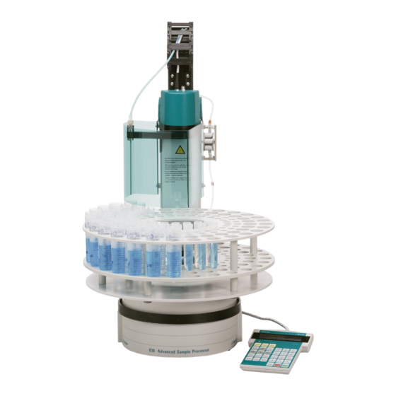
Metrohm 838 Advanced Sample Processor Manuals
Manuals and User Guides for Metrohm 838 Advanced Sample Processor. We have
3
Metrohm 838 Advanced Sample Processor manuals available for free PDF download: Installation Instructions Manual, Manual, Technical Reference
Metrohm 838 Advanced Sample Processor Installation Instructions Manual (109 pages)
Advanced Sample Processor
Brand:
Metrohm
| Category:
Computer Hardware
| Size: 4 MB
Table of Contents
Table of Contents
3
Introduction
7
Instrument Description
7
Scope of Application of the 838 Advanced Sample Processor
7
Instrument Models and Available Versions
8
Table 1 Instrument Models
8
Figure 1 Models 2.838.0X10 Without Injection Valve
8
Figure 2 Models 2.838.0X20 with Injection Valve
8
Table 2 Available Versions
9
Information about this Installation Instructions
10
Note
10
Notation and Pictograms
10
Parts and Controls
11
Overall View
11
Figure 3 Overall View
11
Rear Panel
12
Figure 4 Rear Panel
12
Connections
13
Injection Valve
13
Figure 5 Connection Panel
13
Figure 6 Injection Valve
13
Peristaltic Pump
14
Sensors of the Advanced Sample Processor
14
Figure 7 Peristaltic Pump with 2 Tubing Cartridges
14
Figure 8 Magnet Sensor for Rack Code
14
Safety Notes
15
General
15
Electrical Safety
15
Personal Protection
16
Figure 9 Safety Guard (Example Shown. 6.2751.0Xx for Transfer Robotic Arm)
16
Installation
17
Installation Flowchart
17
Figure 17 Fitting the Ultrafiltration Cell
17
Figure 18 Fitting the Dialysis Cell
17
Table 5 Sample Racks
18
Instrument Setup
19
Setup
19
Mains Connection
19
Figure 10 Mains Connection Socket
19
Fitting the Accessories
20
Connecting the Keypad
20
Connecting the Swing Head
20
Figure 11 Connecting the Keypad
20
Figure 12 Connecting the Swing Head
20
Fitting the Retention Plate
21
Fitting the Needle or Tubing
21
Figure 13 Fitting the Retention Plate
21
Figure 14 Fitting the Needle
21
Fitting the Filtration Cell Holder or Dosino Holder
22
Figure 15 Filtration Cell Holder
22
Figure 16 Dosino Holder
22
Fitting the Ultrafiltration Cell
23
Fitting the Dialysis Cell
26
Figure 19 Fitting the Dialysis Cell into the 6.2057.010 Holder
27
Fitting the Dosino
28
Figure 20 Fitting the Dosino
28
Figure 21 Threaded Adapter GL 45 (6.1618.020)
28
Tubing Connections
29
Figure 22 Fitting Pump Tubing
29
Pump Tubings
31
Table 3 Pump Tubings
32
Connection of the Ultrafiltration Cell
33
Figure 23 Connecting the Ultrafiltration Cell
33
Connecting the Dialysis Cell
35
Figure 24 Capillary Connections for Dialysis
35
Inserting Capillaries or Tubings
40
Fitting the Stand Bracket
40
Figure 25 Inserting Capilliaries or Tubings
40
Figure 26 Stand Bracket
40
Connecting Pumps
41
Connector Dosing Drives and Stirrers
41
Figure 27 MSB Connections
41
Installing the Catch Pan
42
Sample Racks
42
Figure 28 Catch Pan
42
Figure 29 Fitting the Sample Rack
42
Fitting the Safety Guard/Splash Guard
43
Figure 30 Fitting the Safety Guard
43
Connecting External Instruments
44
General Information on Interface Connections
44
Serial Connections (RS232)
45
Remote Interface
45
Connection to Metrohm IC Systems
46
IC System Remotely Controlled by PC
46
Metrohm IC Systems
46
Table 4 MIC Systems
46
Modular Anionic System with Chemical Suppression
47
Figure 31 MIC-2 Interconnection with Anionic System with Chemical Suppression
47
Modular Anionic System with Chemical Suppression and Sample Dilution
48
Figure 32 MIC-2 Interconnection with Anionic System with Chemical Suppression and Sample Dilution
48
Capillary Connections for Sample Dilutions
50
Figure 33 Capilliary Connections for Sample Dilutions
50
Equipping the Work Head of the Mixing Container
51
Figure 34 Equipping the Mixing Container
51
Modular Anionic System with Chemical Suppression and Ultrafiltration of the Samples
52
Figure 35 MIC-2 Interconnection with Anionic System with Chemical Suppression
52
Modular Anionic and Cationic System with Chemical Suppression47
53
Figure 36 MIC-3 Interconnection with Modular Anionic and Cationic System with Chemical Suppression
53
Anionic System with Chemical Suppression and Dialysis
54
Figure 37 MIC-7 Interconnection with Anionic System with Chemical Suppression and Dialysis
54
Modular System with 817 Bioscan for the Sugar Analysis
58
Figure 38 MIC-8 Interconnection with Modular System with 817 Bioscan for Sugar Analysis
58
Connection to 761 Compact IC or 790 Personal IC
59
Figure 39 Interconnection with the 761 Compact IC Via PC (RS232 Only)
59
Figure 40 Interconnection with Compact Systems Via Remote Connection (PC-Controlled)
60
Connection to Metrohm VA Systems
62
Connection to a Metrohm 797 VA Computrace
62
Figure 41 Interconnection with 797 VA Computrace
62
Modular System for Automatic Analysis of Electroplating Baths57
63
Accessories for Sample Volumes Greater than 10 Ml
63
Figure 42 MVA-13 Connection to an Analysis System for Electroplating Baths
63
Figure 43 Accessories for Larger Sample Volumes
63
Sample Racks
65
Metrohm Standard Sample Racks
65
Magnetic Codes
66
Service, Maintenance, Faults
67
Servicing
67
Care and Maintenance
67
Exchanging Pump Tubings
67
Replacing the Filtration Membrane
69
Replacing the Dialysis Membrane
71
GLP Validation - Diagnosis
72
Validation / GLP
72
Annex
73
Filtration
73
Selection of Possible Sample Types
73
Table 6 Filtering Various Samples
73
Filter Working Life
74
Filter Membrane Selection
74
Table 7 Selection of the Filtration Membrane
75
Technical Data
76
Channel Peristaltic Pump
76
Pump Connections
76
Injection Valve
76
Keypad with LCD Display
76
Interfaces
77
MSB Connections
77
Swing Head Connection
77
Lift
77
Turntable
77
Stirrer Connection (DIN Socket)
77
Mains Connection
77
Figure 44 Remote Interface
77
Safety Specification
78
Electromagnetic Compatibility (EMC)
78
Ambient Temperature
78
Dimensions and Material
79
Standard Equipment
80
Metrohm 838 Advanced Sample Processor
80
Keyboard (Optional)
97
Dosing Drive and Units
97
Rührer
97
Sample Racks and Vessels
98
Swing Head
99
Connecting Cables
101
Filtration and Dialysis Accessories
101
Pump Tubing
102
Needles and Tubings
103
Warranty
104
Declaration of Conformity
105
Quality Management Principles
106
Index
107
Advertisement
Metrohm 838 Advanced Sample Processor Manual (101 pages)
Brand:
Metrohm
| Category:
Laboratory Equipment
| Size: 1 MB
Table of Contents
Table of Contents
5
1 Introduction
9
Information about These Instructions for Use
10
Note
10
Notation and Pictograms
10
2 Operation
11
Operating Principles
11
Display
11
Keypad
12
Fig. 1 Key Pad
12
The Keys
13
Instrument Dialog
19
Fig. 2 Dialog Arrangement
20
Data Input
21
Fig. 3 Selection List
21
Text Input
22
Fig. 4 Text Input
23
Configuration
24
Miscellaneous
24
Tower Settings
26
Rackdefinitionen
28
Dosing Units
31
RS232 Settings
32
Composition of a Method
33
Run Sequences and Method Parameters
33
Fig. 5 Sample Series
34
Sample Processor Settings
35
Stirrer Settings
36
Dosing Drive Settings
37
Behavior During Timeout
38
Manual Stop Options
39
Programming of Sequences
40
LEARN Mode
40
TRACE-Funktion
41
Commands
42
Sample Processor Commands
42
Switching Components
46
Dosing Drive Control
47
Communication Commands
49
Auxiliary Commands
53
Managing Methods
54
User-Defined Methods
54
POWERUP Method
55
Run Control
56
Manual Operation
57
Turning the Sample Rack / Positioning the Samples
57
Moving the Lift
57
Setting the Sample Position
58
Pump Control
58
Switching the Stirrers
58
Dosing Device Control
59
Display Interface Signals
59
Interface Control
60
External Pump Control
61
Switching the Injection Valve
61
Rack Initialization
61
Dosing and Liquid Handling
62
Dosimats and Dosinos
62
Fig. 6 Dosino 800 with Dosing Units
62
Fig. 7 Dosing Unit from below
63
Liquid Handling Functions
67
Fig. 8 Dosing Unit - Ports
67
The DOS Command
68
Pictograms
68
Liquid Handling Functions in Detail
69
3 Appendix
72
Sample Racks
72
Metrohm Standard Sample Racks
72
Magnet Codes
73
Rack Data
73
The Remote Interface
76
Output Lines
76
Input Lines
76
SCN Command
77
CTL-Befehl
77
LEARN Mode
78
Setting Lift and Robotic Arm Positions
78
Rack Adjustment
79
Parametrizing Sequence Commands
79
Disabling Keypad Functions
80
Disable Whole Keypad
80
Disable Configuration
80
Disable Parameter
80
Disable Method Storage Functions
81
Disable Display
81
Swing Head Settings
82
Error Messages
84
Initializing the Working Memory
86
Standard Methods
88
Method "LAT
89
Methode "MLAT
91
Method "DT
94
Method "VA
96
4 Index
98
Metrohm 838 Advanced Sample Processor Technical Reference (46 pages)
Advanced Sample Processor
Brand:
Metrohm
| Category:
Laboratory Equipment
| Size: 0 MB
Table of Contents
Table of Contents
2
1 The Metrohm Remote Control Language
5
General Rules
5
Call up of Objects
6
Triggers
7
Status Messages
8
Detailed Status Conditions
8
Error Messages
9
2 The Remote Control Tree
14
Overview
14
Mode - Method Parameters
15
Configuration
18
Info - Instrument Data
21
Setup - Instrument Setup
23
Usermeth - User Defined Methods
25
Assembly - Instrument Components
26
Diagnose - Instrument Diagnosis
29
3 Properties of the RS 232 Interface
30
Data Transfer Protocol
30
Handshake
31
Pin Assignment
34
What Can You Do if Data Transfer Fails
36
4 The Metrohm Remote Interface
37
Pin Assignation of the Remote Interface
37
The Remote Socket
39
Standard Allocation of Remote Lines in Metrohm Measuring and Titration Instruments
40
The Standard Remote Lines
41
Wiring of the Metrohm Standard Remote Cable
42
5 Technical Specifications
43
Keypad
43
Interfaces
43
MSB Connections
43
Channel Peristaltic Pump
43
Pump Connectors
44
Injection Valve
44
Swing Head Connector
44
Lift
44
Turntable
44
Advertisement
Advertisement
Related Products
Metrohm 832 KF Thermoprep
Metrohm 892 Professional Rancimat
Metrohm 893
Metrohm 858
Metrohm 856
Metrohm 848 Titrino plus
Metrohm 804 Ti Stand
Metrohm 806
Metrohm 863
Metrohm 859 Titrotherm
Metrohm Categories
Laboratory Equipment
Measuring Instruments
Security Sensors
Control Unit
Medical Equipment
More Metrohm Manuals
Login
Sign In
OR
Sign in with Facebook
Sign in with Google
Upload manual
Upload from disk
Upload from URL