Sign In
Upload
Manuals
Brands
McQuay Manuals
Remote Control
MicroTech II
McQuay MicroTech II Manuals
Manuals and User Guides for McQuay MicroTech II. We have
8
McQuay MicroTech II manuals available for free PDF download: Operation Manual, Installation Manual, Installation And Maintenance Manual, Operation & Maintenance Manual
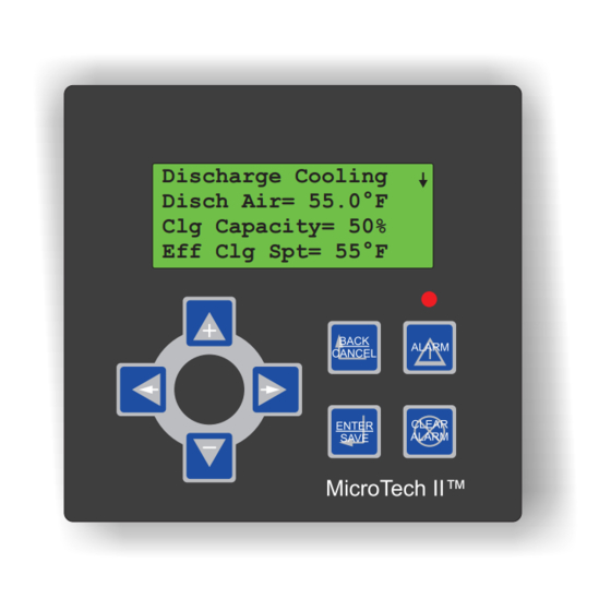
McQuay MicroTech II Operation Manual (136 pages)
Chiller System Manager (CSM) Hardwired Chillers
Brand:
McQuay
| Category:
Controller
| Size: 2.6 MB
Table of Contents
Table of Contents
2
Figures
4
Tables
5
Limited Warranty
6
Notice
6
Reference Documents
7
Revision History
7
CSM Software ID
7
Figure 1. Key to Software Identification
7
Chiller Unit Controller Software Compatibility
8
Table 1. Chiller Unit Controller Program Code Software Compatibility
8
Introduction
9
Figure 2. System Architecture
9
Getting Started
11
Connecting to the CSM
11
PC Requirements
11
Connecting Your PC to the CSM
11
Changing the Csm's IP Address and Date/Time
13
Figure 3. Enter Network Password
14
Figure 4. Niagara Web Administration
15
Connecting to the Csm's User Interface
16
Figure 5. Csm's User Interface Main Screen (Http://<Ip Address>)
17
Connecting to the Csm's User Interface Remotely Using a Modem
18
Using the Csm's User Interface
18
Figure 6. Example of a Configuration Screen (Main > Configuration > System Control)
19
Password Protection
20
Configuring User Accounts
20
Figure 7. User Admin Screen (Main > Configuration > BAS Config > USER ADMIN-Button)
20
User Account Categories
21
Table 2. Default Passwords
21
Table 3. User Admin (Main > Configuration > BAS Config > USER ADMIN-Button)
21
Connecting Chillers and Remote I/O to the CSM
22
On Works
22
Figure 8. Device Addressing (Main > Configuration > Device Addressing)
22
Commissioning a Chiller to a CSM Chiller Number
23
Table 4. Device Addressing (Main > Configuration > Device Addressing)
23
Commissioning a Remote I/O Module to a CSM Remote I/O Letter
24
Figure 9. Service Pin Location on the Microtech II Chiller LON WORKS Communication Module
24
Setting up the Csm's Chiller Data
25
Table 5. Chiller Setup (Main > Configuration > Chiller Setup)
25
Communication Loss Control at the Chiller
26
Setting up the Csm's I/O
27
Table 6. I/O Config (Main > Configuration > I/O Config)
27
Chiller Unit Controller Settings
30
Table 7. Chiller Unit Controller Setup Variables
31
Configuring the Chiller System Manager
32
System Control
32
CSM Control Mode
32
Table 8. System Control (Main > Configuration > System Control)
32
Rapid Restart
33
Low Ambient Lockout
33
Chiller Sequencing Control
34
Sequence Order
34
Figure 10. Chiller Sequence Order Table (Main > Configuration > Chiller Seq)
34
Table 9. Chiller Seq - Chiller Sequencing Order (Main > Configuration > Chiller Seq)
34
Sequencing Logic
36
Table 10. Chiller Seq - Chiller Sequencing Logic (Main > Configuration > Chiller Seq)
36
Figure 11. Typical Primary-Only System
38
Figure 12. Typical Primary-Secondary System
39
Special Sequencing Logic
40
Designating a Standby Chiller
42
Sequencing Chillers with Series-Piped Evaporators
42
Figure 13. Chiller System with Evaporators Piped in the Series/Parallel Configuration
43
Table 11. Example of a Typical Sequence Order with Series-Piped Chillers
43
Stage-Up Inhibiting
44
Load Limiting Control
45
Demand Limiting
45
Table 12. Load Limiting (Main > Configuration > Load Limiting)
45
Figure 14. Screw Chiller Demand Limiting
46
Load Balancing
47
Figure 15. External Signal Demand Limiting Function
47
Soft Loading
48
Figure 16. Soft Load Limit Function
48
Chilled Water Temperature Control
49
Table 13. Chilled Water Supply Temp (Main > Configuration > Chilled Water Supply Temp)
49
Temperature Control
50
Figure 17. CSM Leaving Evaporator Water Temperature Setpoint Flow Chart
51
Figure 18. Typical System with Isolated Chillers
52
Setpoint Reset
52
Figure 19. Return Water or Outdoor Air Reset (English)
53
Figure 20. Return Water or Outdoor Air Reset (SI)
54
Figure 21. External Reset (English)
55
Figure 22. External Reset (SI)
55
Cooling Tower Control
56
Table 14. Clg Tower Control (Main > Configuration > Clg Tower Control)
56
Figure 23. Typical Condenser Water Loop
59
Tower Staging Logic
59
Figure 24. Tower Stage Table (Main>Configuration>Clg Tower Control>Tower Stage Table)
60
Table 15. Actual Cooling Tower Staging
60
Figure 25. Tower Staging Only
62
Figure 26. Tower Staging with Low-Limit Controlled Bypass Valve
63
Figure 27. Tower Staging with Intrastage Controlled Bypass Valve
63
Tower Bypass Valve Control
65
Figure 28. Initial Tower Bypass Valve Position (English)
66
Figure 29. Initial Tower Bypass Valve Position (SI)
66
Chilled Water Flow Control
67
Table 16. Load Flow Control (Main > Configuration > Load Flow Control)
67
Figure 30. Configuration 1: Constant-Speed Single Pump
69
Figure 31. Configuration 2: Constant-Speed Lead/Standby Pump Set
70
Figure 32. Configuration 3: Constant-Speed Sequenced Pumps
70
Figure 33. Configuration 4: Variable-Speed Single Pump
70
Figure 34. Configuration 5: Variable-Speed Lead/Standby Pump Set
71
Figure 35. Configuration 6: Multiple Variable-Speed Pumps
71
Figure 36. Configuration 7: Primary-Only System
71
Pump Logic: Lead/Standby (Auto Lead, Pump 1 Lead, Pump 2 Lead)
72
Pump Logic: Single Pump
72
Pump Logic: Sequenced Constant-Speed Pumps
74
Figure 37. Example of Pump Sequence Order Table (Main > Configuration > Load Flow Control)
75
Pump Logic: Multiple Variable-Speed Pumps
77
Pump Speed Control
79
Loop Bypass Valve Control
80
Scheduling
80
Table 17. Sched (Main > Configuration > Sched)
81
Figure 38. Menu of Schedules (Main > Configuration > Sched > Schedule Icon)
82
Weekly Scheduling
82
Figure 39. Weekly Schedule (Main > Configuration > Sched > Schedule Icon > Weekly)
83
Holiday Scheduling
83
Figure 40. Calendar (Main > Configuration > Sched > Schedule Icon > Calendar)
84
Special-Event Scheduling
84
Figure 41. Special Event Schedule (Main>Configuration>Sched>Schedule Icon>Special Events)
85
Timed Override
85
Bacnet Scheduling
86
External Time Clock
86
Modbus Scheduling
86
Optimal Start
86
Table 18. Optimal Start (Main > Configuration > Optimal Start)
87
Figure 42. Optimal Start Time Line
88
Table 19. Optimal Start Time Increments (in Minutes)
88
BAS Communication
90
Bacnet Settings
90
Table 20. BAS Config - Bacnet (Main > Configuration > BAS Config)
90
Modbus Settings
91
Alarm Notification
91
Table 21. BAS Config - Modbus (Main > Configuration > BAS Config)
91
Physical Alarm Outputs
92
Table 22. Configuring Physical Alarm Outputs (Main > Configuration > Alarms)
92
Table 23. Configuring E-Mail Alarm Notification (Main > Configuration > Alarms)
92
E-Mail Alarm Notifications
93
Table 24. Configuring Bacnet Alarm Notification (Main > Configuration > Alarms)
94
Bacnet Alarm Notifications
95
Saving Your CSM Database Configuration
95
Saving the Database on the CSM
95
Saving the Csm's Configured Database Externally
95
Operator's Guide
97
Chiller System Status
97
CSM Operating State
98
Figure 43. System Status (Main > System Status)
98
Stage-Up Status
101
Stage-Down Status
101
System Capacity
102
Temperatures
102
Figure 44. Chilled Water Temperature Sensor Locations
102
Monitoring Chiller Status
103
Figure 45. Condenser Water Temperature Sensor Locations
103
Figure 46. Chiller Status (Main > System Status > Chiller Status)
104
Status (Chiller Run Mode)
104
Alarm
105
Chiller Run Time (Op Hours)
105
Clear Alarm
105
Chiller Data
106
Comp
106
Load Limiting Status
106
Chilled Water Distribution System Status
107
Cooling Tower Status
107
Override of the Chiller System Manager's Control
107
Local Override of a Chiller
107
Free Cooling BAS Network Override
108
Alarm Monitoring and Control
108
Acknowledging Alarms on the CSM
108
Figure 47. Acknowledging Alarms (Main > View Alarms)
108
Clearing CSM Alarms
109
Clearing Chiller Alarms
109
CSM Alarms and Their Effect on System Control
109
Table 25. CSM Alarms
109
Fault Alarms
111
Problem Alarms
112
Warning Alarms
116
Troubleshooting
118
Using Status Leds
118
Figure 48. Main Board Layout
118
Ethernet Port
119
Heartbeat
119
Lon Port
119
Serial Ports
119
Troubleshooting the Pc's Connection to the CSM
119
Checking the IP Address and Subnet Mask of Your Computer
120
Determining the Csm's IP Address and Subnet Mask
120
Figure 49. Performing the "Ipconfig" Command at the DOS Prompt
120
Figure 50. IP Address Read from a Hyperterminal Boot Sequence
122
Table 26. DB-9 to RJ-45 Null Modem Adapter Pin Assignments
122
Pinging the CSM from Your Computer
123
Checking Internet Explorer Settings
124
Figure 51. Performing the "Ping" Command at the DOS Prompt
124
Figure 52. Important Microsoft Internet Explorer Options
125
Appendix A: Hardwired Chiller Control
126
Setting up the Csm's Additional Chiller Data for a Hardwired Chiller
126
Table 27. Hardwired Chiller Config (Main > Configuration > Chiller Setup)
126
Chiller % RLA from a Hardwired Chiller
127
Figure 53. External Demand Limiting Function Signal
128
Hardwired Chiller - Chilled Water Temperature Control
128
Hardwired Chiller - Load Limiting Control
128
Hardwired Chiller Unit Controller Settings
129
Figure 54. Hardwired Chiller Leaving Water Temperature Setpoint Reset (English)
129
Figure 55. Hardwired Chiller Leaving Water Temperature Setpoint Reset (SI)
129
Hardwired Chiller Sequence of Operation
130
Unavailable and Available Hardwired Chillers
130
Chiller Startup
130
Table 28. Chiller Unit Controller Setup Variables
130
Chiller Shutdown
131
Hardwired Chiller Alarms
131
Chiller Fault Alarms
131
Chiller Problem Alarms
132
CSM Alarms Available for Hardwired Chillers
132
Table 29. CSM Alarms Available for Hardwired Chillers
132
Chiller Data
133
Hardwired Chiller - Communication Loss Control at the Chiller
133
Index
134
Advertisement
McQuay MicroTech II Operation Manual (109 pages)
Applied Rooftop Unit Controller Space Comfort Control (SCC) Used with McQuay models: RPS, RFS, RCS, RPR, RFR, RDT, RDS, RAR and RAH
Brand:
McQuay
| Category:
Controller
| Size: 2.44 MB
Table of Contents
Table of Contents
2
Introduction
4
Getting Started
6
Using the Keypad/Display
6
Menu Structure
6
Display Format
10
Password Protection
10
Keypad Functions
11
Keypad/Display Exercises
11
Keypad/Display Menu Reference
13
System Summary
13
Airflow
16
Temperature
17
Humidity
23
Schedules
24
Setup/Service
26
Active Alarms
38
Previous Alarms
42
Operator's Guide
43
Determining Unit Status
43
Unitstatus
43
Clg Capacity
43
Htg Capacity
43
Clg Status
43
Htg Status
44
Auto/Manual Operation
45
Ctrl Mode
45
Appl Mode
45
Occupancy
46
Occ Mode
46
Occ Src
47
Bypass Time (Tenant Override)
48
Emergency Override
48
Scheduling
48
Setting Controller Date and Time
49
Internal Daily Scheduling
49
Holiday Scheduling
49
One Event Scheduling
49
Optimal Start
50
External Time Scheduling
51
Network Time Scheduling
51
Alarm Monitoring
51
About Alarms
51
Remote Alarm Indication
52
Local Alarm Indication (Keypad/Display)
53
Remote Alarm Clearing
54
Configuring Remote Alarm Output
54
Setting Alarm Limits
56
Unit Configuration/Service Parameters
56
Calibrate Mode
56
Zone (Space) Temperature Sensor
56
Miscellaneous Service Parameters
57
Control Timer Settings
58
Manual Output Control
59
Description of Operation
61
Operating States and Sequences
61
About Operating States
61
Operating State Descriptions
61
Operating State Sequence Chart
64
Startup Control
64
Before Startup
64
Fan Startup
65
Heat/Cool Changeover
65
Temperature Control
66
0-30% Outdoor Air Damper Control
68
Minimum Ventilation Control
68
Economizer
68
Temperature Control
68
Economizer Changeover Method
69
Minimum Ventilation Control
70
Cooling: Multistage
72
Temperature Control
72
Low Ambient Cooling Lockout
73
Compressor Staging
73
Condenser Fan Control
76
Circuit Pumpdown
76
Cooling: Modulating
77
Temperature Control
77
Heating: Multistage
78
Temperature Control
78
Morning Warm-Up Control
79
High Ambient Heating Lockout
79
Discharge Air Low Limit Control
80
Heating: Modulating
80
Temperature Control
80
Morning Warm-Up Control
83
High Ambient Heating Lockout
84
Discharge Air Low Limit Control
84
Dehumidification
85
Enabling Dehumidification
85
Dehumidification Cooling Operation
85
Dehumidification Heating Operation
86
Energy Recovery
86
Enthalpy Wheel Control
86
Exhaust Fan Control
87
Energy Recovery Bypass Damper Control
88
Return Fan Capacity Control
88
Direct Building Static Pressure Control
88
Return Fan Direct Position Control
89
SAF/RAF Differential OA Reset
89
Unoccupied Control
89
Unoccupied Heating (Night Setback)
89
Unoccupied Cooling (Night Setup)
90
Purge
90
Alarm Control
91
Faults
91
Problems
92
Warnings
97
Microtech II DDC Features
99
Direct PID Method
99
Cascaded PID Method
99
PID Control Parameters
100
Period
100
Proportional Band and Integral Time
100
Adjusting PID Control Parameters
100
Correcting System Instability ("Hunting")
100
Correcting System "Sluggishness
101
Software Identification and Configuration
102
Main Control Board (MCB) Configuration
102
Main Control Board (MCB) Data Archiving
103
Keypad/Display Objects
103
Troubleshooting
105
McQuay MicroTech II Installation Manual (58 pages)
Chiller System Manager (CSM)
Brand:
McQuay
| Category:
Control Unit
| Size: 1.29 MB
Table of Contents
Table of Contents
2
Figures
3
Tables
4
Notice
4
Reference Documents
4
Revision History
5
Introduction
6
Figure 1. System Architecture
6
Applying the CSM
8
Typical Chilled Water System
8
Chiller Evaporator Configuration
8
Figure 2. Typical Chilled Water System
8
Figure 3. Parallel Configurations
9
Figure 4. Series/Parallel Configurations
9
Figure 5. Combination Configurations
9
Secondary Pump/Decoupler Line Configuration
10
Figure 6. Common Primary Pump with Separate Isolation Valves
10
Figure 7. Fixed-Speed Secondary Pump
10
Figure 8. Variable-Speed Secondary Pump
10
Loop Bypass Configuration
11
Figure 9. Lead/Standby Secondary Pumps
11
Figure 10. Sequenced Secondary Pumps
11
Figure 11. Pressure-Controlled Loop Bypass
11
General Description
12
Panel Location and Mounting
13
Unpack the CSM Panel
13
Physical Installation
13
Tools Required
13
Mounting
13
Figure 12. Mounting Guide
14
Figure 13. Mounting Detail
15
Removing and Replacing the Cover
16
Removing the Cover of a CSM
16
Replacing the Cover of a CSM
16
Sensor Installation
16
Immersion Water Temperature Sensor
16
Figure 14. Immersion Sensor
17
Figure 15. Brass Thermowell
17
Outdoor Air Temperature And/Or Relative Humidity Sensor
18
Figure 16. Outdoor Air And/Or Relative Humidity Sensor
18
Field Wiring
19
Power Wiring
19
About the CSM Transformer
19
Making the Power Connection to the CSM Transformer
19
Table 1. 120 VAC Models Building Power Termination
19
Ethernet Communications to the User Interface and Bacnet
20
LON WORKS Communications to Chillers and Remote I/O Modules
20
Table 2. International Models - 240 VAC Models Building Power Termination
20
Table 3. Examples of Possible Ethernet Hardware
20
Free Topology Networks
21
Figure 17. Singly Terminated Free Topology
21
Free Topology Restrictions
22
Bus Topology Networks
22
Bus Topology Restrictions
22
Figure 18. Combining Network Segments with a Repeater
22
Figure 19. Bus Network Topology
22
Network Cable Termination
23
Qualified Cables
23
Anaiog/Digital Inputs and Outputs Wiring
23
Onboard I/O Wiring
24
Table 4. Analog/Digital Inputs and Outputs
24
Figure 20. Thermistor Wiring
25
Temperature Inputs
25
0-10 VDC Inputs or 4-20 Ma Inputs
26
Figure 21. Analog Input 0-10VDC Wiring
26
Figure 22. Analog Input 4 to 20 Ma Wiring
27
Analog Input Cable Specifications
28
Digital Inputs
28
Digital Outputs
29
Figure 23. Digital Input Wiring
29
Figure 24. CSM Field Wiring Schematic
30
Remote I/O Wiring
31
Analog Inputs
31
Digital Inputs
32
Analog Outputs
32
Digital Outputs
33
Figure 25. CSM Remote I/O Modules a and B Field Wiring Schematic
35
Figure 26. CSM Remote I/O Modules C and D Field Wiring Schematic
36
Figure 27. CSM Remote I/O Modules E and F Field Wiring Schematic
37
Figure 28. CSM Remote I/O Modules G and H Field Wiring Schematic
38
Modems
39
Internal Modem
39
External Modem
39
Table 5. External Modem Hardware
39
Using the Admin Tool to Configure the Csm/Modem
40
About the Admin Tool
40
Configuring the CSM for Your Modem
40
Table 6. External Modem Modular Adapter Assembly Pin Assignments
40
Table 7. Modem Configuration Parameters (Ras.properties)
41
Initial Checkout and Troubleshooting
43
Checking the Heartbeat LED
43
About the Battery
43
Figure 29. Main Board Layout
44
Appendix A: Hardwired Chiller Control
45
Figure 30. Typical Hardwired Chiller Field Wiring Diagram
46
Hardwired Chiller Remote I/O Module Analog Inputs
47
Chiller % RLA (AI 1)
47
Chillers with % RLA Output
47
Figure 31. Direct % RLA Signal from Chiller
47
Chillers Without % RLA Output
48
Figure 32. Measuring Compressor Amps with a Current Output Current Transducer
48
Table 8. Signal Averaging Device Specification
48
Chiller Leaving Evaporator and Leaving Condenser Water Temperatures (AI 3 and AI 4)
49
Table 9. Current Transducer Specification
49
Table 10. Temperature Sensor Specification
49
Hardwired Chiller Remote I/O Module Digital Inputs
50
Evaporator and Condenser Flow Proving (DI 1 and DI 2)
50
Hardwired Chiller Alarms (DI 3 and Optionally DI 4)
50
Hardwired Chiller Remote I/O Module Analog Outputs
50
Hardwired Chiller Leaving Water Temperature Setpoint Reset (AO 1)
50
Hardwired Chiller Load Limiting (AO 2)
51
Hardwired Chiller Remote I/O Module Digital Outputs
51
Evaporator and Condenser Pump Control (Relay 1)
51
Evaporator and Condenser Pump Control (Relay 2 and Relay 3)
51
Transformer Usage
51
Table 11. Voltage to Current Converter (0-10 VDC to 4-20 Ma) Specification
51
Table 12. Hardwired Chiller's Hardware Transformer Usage
52
Figure 33. Hardwired Chiller's Possible Hardware Requirements
53
Maintenance
54
Cleaning
54
Required Battery Maintenance
54
Replacing the Battery
54
Parts List
55
Table 13. Standard Replacement Parts
55
Warranty
56
Warranty Return Material Procedure
56
Replacement Parts
56
Index
57
Advertisement
McQuay MicroTech II Installation And Maintenance Manual (48 pages)
Vertical Self-Contained Systems Unit Controller
Brand:
McQuay
| Category:
Controller
| Size: 6.36 MB
Table of Contents
Table of Contents
2
Introduction
3
General Description
4
Component Data
4
Main Control Board (MCB)
5
Analog Inputs Terminal Blocks
6
Binary Inputs Terminal Blocks
6
Binary Outputs Terminal Blocks
6
RS-485 Communications Terminal Block
6
Power Supply Terminals
6
Keypad/Lcd Display Connection
6
Communication Modules
6
Plug-In Bacnet/Ip Communications Module
6
Plug-In Bacnet MS/TP Communications Module
6
Lonworks® Communication Modules
7
RS-232 Connection Port
7
15 VDC Supply Connection
7
Main Control Board Leds
8
Auxiliary Control Boards (Ccb1And CCB2)
8
Analog Inputs Terminal Block (J8)
9
Binary Inputs Terminal Blocks (J9 and J10)
9
Binary Outputs Terminal Block
10
RS-485 Communications Module
10
Power Supply Terminals (J1)
10
J7 Terminal Block
10
J2 Terminal Block
10
Main Control Board (MCB) Output Relays and Triacs
10
Auxiliary Control Boards (CCB1 and CCB2) Output Relays
10
Keypad/Display
10
Temperature Sensors
11
Pressure Transducers
11
Humidity Sensors
11
Actuators
11
Adjustable Frequency Drives (Afds)
11
Field Wiring
12
Field Output Signals
12
Outside Air Damper
12
Fan Operation Output
12
Remote Alarm Output
12
VAV Box Output
13
Cooling-Only Units
13
Cooling-Only Units with Field Supplied Heat
13
Units with Staged Heat
13
Units with Modulating Heat
14
Pump Start Output
14
Field Analog Input Signals
14
Zone Temperature Sensor Packages
14
Zone Sensor Without Remote Setpoint Adjustment
14
Zone Sensor with Remote Setpoint Adjustment
14
Tenant Override (Timed)
15
External Discharge Air Reset Signal
15
Field Actuator Feedback
16
Field 100% OA Damper Actuator
16
Humidity Sensors
17
Humidity Sensor-Discharge Air Control (DAC) Unit
17
Field Binary Input Signals
18
Manual Cooling and Heating Enable
18
Cooling Enable
18
Heating Enable
18
Manual Unit Enable
18
External Time Clock or Tenant Override
18
Miscellaneous Output Signals
18
Service Information
19
Controller Inputs
19
Analog Inputs-Main Control Board (MCB)
19
Analog Inputs-Auxiliary Control Boards (CCB1 and CCB2)
21
Binary Inputs-Main Control Board (MCB)
21
Binary Inputs-Auxiliary Control Boards (CCB1 and CCB2)
21
CCB1 and CCB2
22
Controller Outputs
23
Binary Outputs-Main Control Board (MCB)
23
Binary Outputs-Auxiliary Control Boards (CCB1 and CCB2)
24
Ccb1 & Ccb2
24
Compressors-2 Stages
24
Compressors-3 Stages
25
Compressors-4 Stages
25
Small Compressors & 1 Large Compressor-5 Stages
25
Small Compressors & 2 Large Compressors-6 Stages
25
Compressors-6 Stages
26
Software Identification and Configuration
27
Main Control Board (MCB) Configuration
27
Main Control Board (MCB) Data Archiving
28
Keypad/Display Objects
28
Typical Wiring Diagrams
29
Test Procedures
37
Troubleshooting Main Control Board (MCB)
37
MCB Battery
37
MCB Data Archiving
37
MCB "Cold" Reboot
37
MCB LED Power-Up Sequence
38
MCB LED Startup Error Codes
39
Battery Test
40
Flash CRC Tests
40
SRAM Test
41
Communication Port Tests
41
IP Register Test
41
Troubleshooting Auxiliary Control Boards (Ccb1And CCB2)
41
Hardware Check
41
RS-485 Communication Module Status Leds
41
Troubleshooting Keypad/Display
42
Keypad/Display Power up Initialization
42
Troubleshooting Temperature Sensors
43
Troubleshooting Communications Cards
43
Bacnet/Ip Module
44
Bacnet MS/TP Module
44
Lonmark Module
44
Troubleshooting Static Pressure Transducers
44
Troubleshooting Refrigerant Pressure Transducers
46
Parts List
47
McQuay MicroTech II Operation & Maintenance Manual (32 pages)
Unit Ventilator Controls for AAF® -HermanNelson® Classroom Unit Ventilators
Brand:
McQuay
| Category:
Remote Control
| Size: 2.17 MB
Table of Contents
Table of Contents
2
Abbreviations Table
3
Safety Information
4
Introduction
5
Getting Started
5
Using the Local User Interface (LUI)
5
2-Digit 7-Segment Display
5
On/Stop Button and LED
5
Fan Button
6
Mode Button
6
Arrow Buttons
6
Func Button
6
Viewing Actual Temperature (IAT)
6
Using the LUI to Adjust Setpoint Offset
6
LUI Security Levels
6
Changing LUI Security Level
6
Why Can't I Use the Mode or Fan Button, or Adjust Setpoint Offset
6
LUI Menu Reference
7
Changing an LUI Menu Item
7
Description of Operation
9
State Programming
9
UVC Unit Modes
10
Off Mode
10
Night Purge Mode
10
Fan Only Mode
11
Emergency Heat Mode (Super State)
11
Full Heat State
11
Cant Heat State
12
Auto Mode
12
Heat Mode (Super State)
12
Heat State
13
Low Limit State
13
Cant Heat State
13
Cool Mode (Super State)
14
Econ State
15
Econ Mech State
15
Mech State
16
Cant Cool State
16
DA Heat State
16
Low Limit State
16
Active Dehumidify State
17
Software Model 04)
17
Special Purpose Unit Modes
17
Pressurize Mode
17
Depressurize Mode
17
Purge Mode
17
Shutdown Mode
17
Energy Hold off Mode
17
UVC Unit Mode Priority
17
Occupancy Modes
18
Occupied Mode
19
Unoccupied Mode
19
Standby Mode
19
Bypass Mode
19
Networked Occupancy Sensor Capability
19
Unit-Mounted Time-Clock
19
Unit-Mounted Tenant Override Switch
19
Remote Wall-Mounted Sensor Tenant Override Switch
19
Remote Wall-Mounted Sensor Status LED
19
Space Temperature Setpoints
19
LUI Setpoint Offset Adjustment
20
Adjustment (Optional)
20
Remote Wall-Mounted Sensor with 55°F to 85°F Adjustment (Optional)
20
Effective Setpoint Calculation Examples
20
PI Control Loops
21
Discharge Air Temperature Control
21
PI Control Parameters
22
Proportional Band
22
Integral Time
22
Indoor Air Fan Operation
23
Auto Mode
23
Occupied, Standby and Bypass Operation
23
Unoccupied Operation
23
Cycle Fan
23
Off Delay
23
Outdoor Air Damper Operation
23
Minimum Position
23
Economizer Operation
23
Temperature Comparison Economizer
23
Temperature Comparison with Enthalpy Comparison Economizer (Optional)
24
Networked Space Humidity Sensor Capability
24
Networked Outdoor Humidity Sensor Capability
24
CO 2 Demand Controlled Ventilation (Optional)
24
Networked Space CO Sensor Capability
24
ASHRAE Cycle II
24
Compressor Operation
24
Compressor Envelope
24
Compressor Cooling Lockout
25
Minimum on and off Time
25
Compressor Start Delay
25
Outdoor Air Fan Operation
25
Floating-Point Actuator Auto-Zero, Overdrive and Sync
25
External Binary Inputs
25
External Binary Input 1
25
Unoccupied Input Signal
25
Dewpoint/Humidity Input Signal (Optional, Software Model 04)
25
External Binary Input 2
25
Remote Shutdown Input Signal
26
External Binary Input 3
26
Ventilation Lockout Input Signal
26
Exhaust Interlock Input Signal
26
External Binary Outputs
26
External Binary Output 1
26
Lights On/Off Signal
26
External Binary Output 2
26
Fault Signal
26
External Binary Output 3
26
McQuay MicroTech II Installation And Maintenance Manual (52 pages)
Vertical Self-contained Systems Unit Controller, Used with McQuay models: SWP and SWT
Brand:
McQuay
| Category:
Controller
| Size: 3.09 MB
Table of Contents
Table of Contents
2
Introduction
3
General Description
5
Component Data
5
Main Control Board (MCB)
6
Communication Cards
7
Auxiliary Control Boards (Ccb1And CCB2)
9
Main Control Board (MCB) Output Relays and Triacs
11
Auxiliary Control Boards (Ccb1And CCB2) Output Relays
11
Keypad/Display
11
Temperature Sensors
12
Pressure Transducers
12
Humidity Sensors
12
Actuators
12
Variable Frequency Drives (Vfds)
12
Field Wiring
13
Field Output Signals
13
Outside Air Damper
13
Fan Operation Output
13
Remote Alarm Output
13
VAV Box Output
14
Staged Cooling Outputs
15
Pump Start Output
15
Field Analog Input Signals
15
Zone Temperature Sensor Packages
15
Tenant Override (Timed)
16
External Discharge Air Reset Signal
16
Field Actuator Feedback
17
Humidity Sensors
18
Field Binary Input Signals
19
Manual Cooling and Heating Enable
19
Manual Unit Enable
19
External Time Clock or Tenant Override
19
Miscellaneous Output Signals
19
Service Information
20
Controller Inputs
20
Analog Inputs-Main Control Board (MCB)
20
Analog Inputs-Auxiliary Control Boards (CCB1 and CCB2)
22
Binary Inputs-Main Control Board (MCB)
23
Binary Inputs-Auxiliary Control Boards (CCB1 and CCB2)
23
Controller Outputs
25
Binary Outputs-Main Control Board (MCB)
25
Binary Outputs-Auxiliary Control Boards (CCB1 and CCB2)
27
2-Compressors/2-Stages
27
3-Compressors/3-Stages
27
4-Compressors/4-Stage
28
3-Small Compressors & 1-Large Compressor/5-Stage
28
2-Small Compressors & 2-Large Compressors/6-Stage
28
1-Small Compressor & 3-Large Compressors/6-Stage
29
6-Compressors/6-Stage
29
Software Identification and Configuration
30
Main Control Board (MCB) Configuration
30
Main Control Board (MCB) Data Archiving
32
Keypad/Display Objects
32
Typical Wiring Diagrams
33
Test Procedures
41
Troubleshooting Main Control Board (MCB)
41
SRAM Test
45
Troubleshooting Auxiliary Control Boards (Ccb1And CCB2)
45
Troubleshooting Keypad/Display
46
Troubleshooting Temperature Sensors
47
Troubleshooting Communications Cards
48
Troubleshooting Static Pressure Transducers
48
Troubleshooting Refrigerant Pressure Transducers
50
Parts List
51
McQuay MicroTech II Installation And Maintenance Manual (16 pages)
Chiller Unit Controller LonWorks Communication Module
Brand:
McQuay
| Category:
Controller
| Size: 0.4 MB
Table of Contents
Table of Contents
2
Figures
2
Revision History
3
Reference Documents
3
General Information
4
Description
4
Figure 1. Microtech II Lonworks Communications Module (Component Side)
4
Application
5
Component Data
5
Figure 2. Building Automation System
5
8-Pin Header
6
Figure 3. Microtech II Lonworks Communications Module Major Components
6
Light Emitting Diodes (Leds)
6
Lonworks Network Connector
6
Service Pin
6
Lonmark Profile Software
7
Neuron
7
Transceiver
7
Specifications
7
Installation
8
Mounting
8
Mounting a Microtech II Lonworks Communications Module
8
Figure 4. Serial Card Slot Location on Unit Controller
9
Figure 5. Serial Card Slot Detail
9
Figure 6. Network Cable Routing and Connections
10
Figure 7. Network Connection Detail
10
Replacing an Existing Microtech II Lonworks Communications Module
11
Unit Setup for Network Control
11
Integration
12
Connecting to the Network
12
Network Topology
12
Figure 8. Singly Terminated Free Topology Networks
12
Figure 9. Combining Network Segments with a Repeater
13
Figure 10. Doubly Terminated Network Topology
13
Physical Network
14
Addressing and Establishing Communications
15
Lonworks Network Addressing
15
Commissioning the Network
15
External Interface File (XIF)
15
Configuring the Unit Controller
15
Service Information
16
Test Procedures
16
Replaceable Parts List
16
Network Connection Plug
16
Replacement Kit
16
McQuay MicroTech II Installation And Maintenance Manual (13 pages)
Brand:
McQuay
| Category:
Chiller Control System
| Size: 0.47 MB
Table of Contents
Table of Contents
2
Figures
2
Revision History
3
Reference Documents
3
Limited Warranty
4
General Information
5
Description
5
Application
5
Figure 1. Modbus Communication Module - RS-485 (Component Side)
5
Component Data
6
Modbus Connector
6
8-Pin Header
6
Figure 2. Modbus Communication Module Major Components
6
Installation
7
Mounting
7
Mounting a Modbus Communication Module
7
Figure 3. Serial Card Slot Location on Unit Controller
8
Figure 4. Serial Card Slot Detail
8
Figure 5. Network Cable Routing and Connections
9
Figure 6. Network Connection Detail
9
Replacing an Existing Modbus Communication Module
10
Unit Setup for Network Control
10
Integration
11
Connecting to the Network
11
Network Topology
11
Addressing and Establishing Communications
11
Network Address and Baud Rate
11
Configuring the Unit Controller
11
Service Information
13
Test Procedures
13
Replaceable Parts List
13
Network Connection Plug
13
Replacement Kits and Parts
13
Advertisement
Related Products
McQuay MicroTech III
McQuay MicroTech III RAH
McQuay MicroTech III RDS
McQuay MicroTech III RCS
McQuay MicroTech III RDT
McQuay MicroTech III RFS
McQuay MicroTech III RPS
McQuay MicroTech III SWP
McQuay MicroTech III SWT
McQuay MicroTech 2000
McQuay Categories
Air Conditioner
Chiller
Heat Pump
Controller
Air Handlers
More McQuay Manuals
Login
Sign In
OR
Sign in with Facebook
Sign in with Google
Upload manual
Upload from disk
Upload from URL