Sign In
Upload
Manuals
Brands
LS ELECTRIC Manuals
Control Unit
XGT Series
LS ELECTRIC XGT Series Manuals
Manuals and User Guides for LS ELECTRIC XGT Series. We have
14
LS ELECTRIC XGT Series manuals available for free PDF download: User Manual, Installation Manual
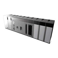
LS ELECTRIC XGT Series User Manual (804 pages)
Programmable Logic Control
Brand:
LS ELECTRIC
| Category:
Controller
| Size: 22 MB
Table of Contents
Table of Contents
12
Chapter 1 Introduction
26
Features of XG5000
26
System Requirements for XG5000
28
Installation of XG5000
29
Installation of USB Device Driver
35
Confirmation of Installed USB Device Driver
39
Chapter 2 Basic Application
48
Screen Configuration
48
Menu Configuration
49
Tool Box
56
Status Display Line
62
Change View Window
62
Application of Dialog Box
65
Open/Close Project
66
Open Project
66
Close Project
66
Save Project
66
Convenient Edit Functions
67
Cut-Paste
67
Copy - Paste
68
Drag and Drop
70
Edit Window Zoom-In, Zoom-Out
73
Options
75
XG5000 Option
75
XG5000 Common Editor
77
XG5000 Color Options
78
Online Options
80
LD Option
83
LD Font/Color Option
84
SFC Option
85
SFC Font/Color
87
ST Option
88
ST Font/Color
90
Project Configuration
92
Project File Management
94
New Project
94
Open Project
98
Open from PLC
98
Save Project
99
Save as
100
Open KGLWIN File
103
KGLWIN Project Conversion Rules
104
Confirm Converted File
113
Project Item
115
Add Item
115
Import Item from File
125
Export to File
128
Item Register Information
130
Change Program Sequence
132
Data Memory
132
Compare Project
141
Project Password
144
Set Password
144
Change Password
145
Delete Password
147
Program Block Password
149
Set Password
149
Change Password
150
Delete Password
152
Setup of Integrated Project Network
155
Network Configuration
155
Deletion of Network
160
Deletion of Communication Module
161
Deletion of P2P
164
Setup of High-Speed Link
166
Chapter 4 Variable/Comment
172
Variable/Comment
173
View Device
173
View Flag
174
Variable/Comment Edit
177
Variable/Comment Register
177
Copy, Cut, Delete, Paste
179
Insert Line
183
Delete Line
185
Automatic Fill
186
Drag and Drop
188
Undo/Redo
189
Export to File
190
U Device Automatic Register
191
Preview
198
Print
200
Convenient Functions
200
Sharing Variable
204
Saving Variable/Comment
204
CSV File Structure
206
Import External Variable in XG-PD
208
XGK Automatic Variable
211
Global Variable
211
Device Comment
212
Registering Global Variable
213
Registering Local Variable
216
Adding EXTERNAL Variable
217
Chapter 5 LD Edit
222
Limits
222
Program Edit
222
Edit Tools
222
Input Contact Point
224
Input or Contact Point
225
Input Variable/Device
227
Input Line
229
Input Coil
230
Input Application Instruction
231
Input Comment
236
Input Label
238
Insert Cell
240
Insert Line
241
Delete Factor
242
Delete Cell
242
Delete Line
243
Copy/Cut/Paste
244
Drag and Drop
246
Undo and Redo
249
Change Columns
250
LD View Properties
252
Program View
253
IL Program View
253
Program Magnification Change
254
View Device
254
View Variable
255
View Device/Variable
255
View Device/Comment
255
Optimize Program
257
Block Mask Instruction
259
Bookmark
261
Go to
265
Chapter 6 IL Edit
270
Screen Configuration
270
IL Window
270
Instruction Input Window
271
Limits
271
Program Edit
272
Overwrite/Insert Mode
272
Input Instruction
274
Input Application Instruction
275
Input Rung Comment
276
Change Instruction
278
Insert Line
279
Delete Line
280
Paste, Copy, Cut
281
Undo/ Redo
283
Program View
284
Change Program Magnification
284
View Device
284
View Variable
285
View Device, Variable
285
View Device, Comment
286
Additional Edit Function
287
Block Mask Instruction
287
Bookmark
289
Go to
291
Go to Step
291
Go to Label
293
Go to Rung Comment
294
Go to END Instruction
296
Chapter 7 Programming Convenience
298
Cross Reference
298
View All Device
298
Output Cross Reference Instantly
300
Check Duplicated Coil Instantly
302
Used Device
305
Execute Used Device
305
View Device Uses
307
Check Program
309
Check Program Setting
309
Check Result Trace
314
Logic Error
315
Grammar Error
317
Chapter 8 Find/Replace
328
Find Device
328
Find Next Device
332
Find Text
336
Find Next Text
339
Find All Text
340
Replace Device
342
Replace Device
346
Replace All Device
349
Replace Text
355
Replace All Text
360
Find Again
364
Chapter 9 Parameters
366
Basic Parameters
366
I/O Parameters
372
Base Module Information Setting
374
Module Information Setting Based on Slots
375
I/O Parameter Edit Function
378
Detailed Module Information Setting
383
I/O Parameter Print Function
393
Chapter 10 Online
396
Connect Options
396
Local Connect Setting
396
Remote 1 Connect Setting
399
Remote 2 Connect Setting
402
Connect/Disconnect
403
Connect
403
Write
408
Read
411
Change Mode
412
Compare to PLC
413
Reset PLC
420
Clear PLC
422
Clear Memory
423
Clear Latch
424
PLC Information
428
CPU Information
428
CPU Performance
429
Password
431
PLC RTC Setting
433
PLC History
435
Error Log
435
Change Mode History
436
Shut down Log History
437
System Log
438
PLC Error/Warning
439
Flash Memory Setting
442
Forced I/O Setting
444
Skip I/O
451
Fault Mask
460
Module Changing Wizard
463
Custom Events
470
Example
470
Event Setting
474
Event History
483
Chapter 11 Monitoring
488
Monitoring
488
Start/Stop Monitoring
488
Change Current Value
488
Pause Monitoring
490
LD Program Monitoring
493
Variable Monitoring
497
Register Monitoring
498
View
506
Operation of Monitoring
509
Find
510
Print
510
Shortcut Keys
511
Alignment
511
System Monitoring
513
Basic Application
513
Connect/Disconnect
514
System Synchronization
514
All I/O Modules ON/OFF
515
Selected I/O Modules ON/OFF
515
Change Current Value
516
Information Display of Power Module
516
Information Display of CPU Module
517
Information Display of Communication Module
518
Information of Special Module
519
Start/Stop Monitoring
520
Special Module Monitoring
520
Save
521
Open
522
Move Base
522
Preview
523
Device Monitoring
524
Basic Application
524
Device Areas
525
Data Format and Display Items
525
Edit Data
540
Save Device
541
Open Device
543
Data Value Setting
545
Clear Data
546
Write to PLC
547
Read from PLC
548
Write Selected Area on PLC
549
Start/Stop Monitoring
550
Change Current Value
551
PLC Type Settings
552
Screen Zoom-In/Zoom-Out
552
Automatic Width/Height Adjustment
553
Properties
553
Page Setting
554
Special Module Monitoring
555
Trend Monitoring
559
Example
559
Setting Trend Monitoring
562
Setting Graph
564
Setting Graph Window
567
Graph Function
568
Data Traces
574
Connect
576
Setting Trace
576
Setting Graph
580
Trace
582
Simulation
582
Graph Function
584
File Function
584
View Function
585
PID Monitor
587
Basic Instructions
587
Save File
589
Open File
591
Setting/Adjustment of Loop Name
593
Add/Delete Selected Loop
594
Print/Print Preview
595
Connection to PLC
595
Write Loop Data to PLC
596
Write All Data to PLC
596
Read Loop Data from PLC
596
Read All Data from PLC
597
Monitor Start/End
597
Change Current Value During Monitoring
598
Graph
599
Graph Related Function
599
Edit Function
601
Advertisement
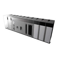
LS ELECTRIC XGT Series User Manual (1111 pages)
XGI CPU Module
Brand:
LS ELECTRIC
| Category:
Control Unit
| Size: 32 MB
Table of Contents
Revision History
7
Chapter 1 Overview
26
Chapter 2 System Configuration
34
Product List
36
Basic System
42
Network System
47
Remote I/O System
48
General Specifications
49
Chapter 3 CPU Module
50
Performance Specification
51
Name of each Part and Function
55
Program Instruction
58
Operation Processing During Momentary Power Failure
59
Program Execution
60
Parameter Setting
64
Basic Parameter
64
Run Mode
74
Stop Mode
75
Operation Mode Change
76
Program Memory
77
Menu Configuration
81
Self-Diagnosis Function
90
I/O Module Check Function
90
Remote Functions
98
Forced I/O On/Off Function
99
Saving Operation History
102
External Device Error Diagnosis
104
I/O Module Skip
106
Changing Module During Operation
107
I/O No. Allocation Method
108
Chapter 6 Local Ethernet Function
110
Ntp Client
116
Socket Service
138
Packet Capture
146
Operation Mode
151
Memory Card Folder Structure
165
File Commands
170
File Write
173
File Rename
183
Pid Control
191
PID Control Operation
192
PID Function Block
197
PID Flag Configuration
202
Common Bit Area
204
Individual Data Area
207
Hardware Configuration
216
Program Example1
220
Cascade Operation
234
Web Server Function
238
How to Use Web Server
241
Dash Board Configuration
242
Chapter 10 I/O Module
257
Point AC110V Input Module
266
Point AC220V Input Module
267
Point Relay Output Module
270
Point Triac Output Module
272
Chapter 11 Power Module
297
Selection Method
297
Specifications
299
Part Names
300
Chapter 13 Installation and Wiring
305
Installation Environment
305
Handling Precautions
307
Attachment/Detachment of Module
312
Wiring Precautions
314
Power Wiring
314
I/O Module Wiring
316
Grounding Wiring
316
Cable Specification for Wiring
317
Chapter 14 Maintenance and Repair
318
Maintenance and Inspection
318
Daily Inspection
319
Periodic Inspection
320
Requirements for Conformance to EMC Directive
321
EMC Standard
321
Control Panel
322
Requirement to Conform to the Low-Voltage Directive
325
Chapter 16 Troubleshooting
327
Action When Power LED Is off
329
Action When ERR LED Is Blinking
330
Action When I/O Module Does Not Work Normally
332
Questionnaire for Troubleshooting
335
Chapter 1 Motion Control Operation
339
Motion Parameter
342
Axis Parameter
350
Ethercat Communication
373
What Is Ethercat
373
Chapter 2 Motion Function Block
386
Axis Status
386
Monitor Commands
635
Chapter 3 Motion Control Function
646
Interpolation Control
647
Speed Control
652
Torque Control
653
Single-Axis Position Control
667
Single-Axis Speed Control
673
Single-Axis Torque Control
675
Switching Control
679
Linear Interpolation Control
684
Manual Control
719
Other Functions
729
LS ELECTRIC XGT Series User Manual (258 pages)
Brand:
LS ELECTRIC
| Category:
Controller
| Size: 6 MB
Table of Contents
Table of Contents
12
Chapter 1 Introduction
18
Guide to Use this Manual
18
Features
19
Terminology
22
Chapter 2 System Configuration
27
XGB System Configuration
27
Product List
28
Classification and Type of Product Name
30
Classification and Type of Main Unit
30
Classification and Type of Expansion Module
31
Classification and Type of Special Module
32
Classification and Type of Communication Module
33
Classification and Type of Option Module
34
System Configuration
35
Cnet I/F System
35
Ethernet System
38
Chapter 3 General Specifications
39
General Specifications
39
Chapter 4 CPU Specifications
41
Performance Specifications
41
Names of Part and Function
43
Power Supply Specifications
44
Calculation Example of Consumption Current/Voltage
47
Battery
49
Battery Specification
49
Chapter 5 Program Configuration and Operation Method
51
Program Instruction
51
Program Execution Methods
51
Operation Processing During Momentary Power Failure
52
Scan Time
53
Scan Watchdog Timer
54
Program Execution
55
Configuration of Program
55
Program Execution Methods
55
Interrupt
57
Operation Mode
71
RUN Mode
71
STOP Mode
72
DEBUG Mode
72
Change Operation Mode
76
Memory
77
Program Memory
77
Data Memory
78
Data Retain Area Setting
78
Data Memory Map
80
Chapter 6 CPU Functions
81
Type Setting
81
Parameter Setting
82
Basic Parameter Setting
82
I/O Parameter Setting
83
Self-Diagnosis Function
85
Saving of Error Log
85
Troubleshooting
86
Remote Functions
87
Forced Input/Output on and off Function
88
Force I/O Setup
88
Direct Input/Output Operation
90
Diagnosis of External Device
91
Allocation of Input/Output Number
92
Online Editing
94
Reading Input/Output Information
98
Monitoring
99
RTC Function
105
How to Use
105
Exernal Memory Module
107
Memory Module Specification
107
Memory Module Structure
107
How to Use Memory Module
108
How to Use When Password Is Set
112
Clear All PLC
115
Password Setting Per Program Block
116
Chapter 7 Input/Output Specifications
119
Introduction
119
Digital Input Specifications of Main Unit
126
XEC-DR32H / XEC-DN32H Input Unit (Source/Sink Type)
126
XEC-DR64H / XEC-DN64H Input Unit (Source/Sink Type)
127
Digital Output Specification of Main Unit
128
XEC-DR32H Output Unit
128
XEC-DR64H Output Unit
129
XEC-DN32H Output Unit (Sink Type)
130
XEC-DP32H Output Unit (Source Type)
131
XEC-DN64H Output Unit (Sink Type)
132
XEC-DP64H Output Unit (Source Type)
133
Digital Input Module Specification
134
Point DC24V Input Module (Source/Sink Type)
134
Point DC24V Input Module (Sink/Source Type)
135
Point DC24V Input Module (Source/Sink Type)
136
Point AC110V Input Module
137
Digital Output Module Specifications
138
Point Relay Output Module
138
Point Transistor Output Module (Sink Type)
140
Point Transistor Output Module (Sink Type)
141
Point Transistor Output Module (Source Type)
143
Point Transistor Output Module (Source Type)
145
Combined Module Digital Input Specification
146
Point DC24V Input Part (Source/Sink Type)
146
Point DC24V Input (Source/Sink Type)
147
Combined Module Digital Output Specification
148
Point Relay Output Part
148
Point Transistor Output (Sink Type)
149
IO Wiring by Using Smart Link Board
150
Smart Link Board
150
Advertisement
LS ELECTRIC XGT Series User Manual (364 pages)
Programmable Logic Control Ethernet Module
Brand:
LS ELECTRIC
| Category:
Control Unit
| Size: 11 MB
Table of Contents
Safety Instructions
4
Revision History
8
Chapter 2 Product Specifications
28
General Specifications
28
Performance Specifications
29
Structure and Characteristics
33
Test Operation
52
System Diagnosis
77
E-Mail Service
215
Chapter 7 Server Service
228
Modbus Server
241
Ethernet / IP Server
245
Chapter 8 Additional Functions
290
Remote Communication
290
Chapter 9 Troubleshooting
300
Troubleshooting by Error
328
Chapter 10 EMC Standard
330
Requirement to Conform to the Low-Voltage Directive
333
ASCII Code Table
355
Warranty
362
LS ELECTRIC XGT Series User Manual (258 pages)
Brand:
LS ELECTRIC
| Category:
Control Unit
| Size: 6 MB
Table of Contents
Safety Instructions
4
Revision History
8
Chapter 1 Overview
15
General Specifications
22
Chapter 2 Product Configuration
23
Performance Specifications
24
Structure and Characteristics
27
Product Installation
32
System Diagnosis
57
Chapter 5 Server Service
100
Chapter 6 Additional Functions
132
Remote Communication
132
Chapter 7 Troubleshooting
166
Chapter 7 Toubleshooting
166
Troubleshooting by Error
187
EMC Standard
190
System Warning
212
ASCII Code Table
222
Function Block
226
Warranty
256
Environmental Policy
256
LS ELECTRIC XGT Series User Manual (154 pages)
Pnet Slave I/F Module
Brand:
LS ELECTRIC
| Category:
Control Unit
| Size: 6 MB
Table of Contents
Table of Contents
10
Chapter 1 Overview
14
How to Use the User's Manual
14
Characteristics of Product
16
Characteristics of Pnet Remote I/F Module
16
Characteristics of Pnet Slave I/F Module
17
Product Configuration
18
Product Configuration of the Pnet Remote I/F Module
18
Product Configuration of the Pnet Slave I/F Module
20
Software to Use the Product
21
Software Check Point
21
Xg5000
21
Check of Version
22
Version Compatibility List
23
Pnet Remote I/F Module Compatibility List
23
Pnet Slave I/F Module Compatibility List
23
Notice in Using
24
Chapter 2 Product Specification
26
General Specifications
26
Communication Module Specification
27
Pnet Remote I/F Module Specification
27
Pnet Slave I/F Module Specification
28
Communication Cable Specification
29
Profibus-DP Cable Specification
29
Terminating
30
Pnet Terminating
30
Chapter 3 System Configuration
32
Notices in Selecting Module
32
Names of each Part (Pnet Remote I/F Module)
33
Basic System Configuration
33
Names and Functions of each Part
33
Available Product List
35
Names of each Part (Pnet Slave I/F Module)
37
Basic System Configuration
37
Names and Functions of each Part
37
System Configuration Example
39
Pnet System (GMWIN)
39
Pnet System (XG5000)
40
Chapter 4 Communication Programming
42
How to Set Master Module
42
High-Speed Link
42
Xg5000'S Link Parameter Setting
43
High-Speed Link Communication Status Flag Information (XGT)
45
How to Register XGT Profibus-DP Remote Module
47
Create New Project
47
Set IO Parameter
48
How to Set Pnet Slave I/F Module Parameter
52
High-Speed Link Parameter Setting
52
High-Speed Link Communication Diagnosis
54
Sycon Parameter Setting
55
Chapter 5 Profibus-DP Communication
62
Overview
62
Communication Specification
62
Basic Performance
63
Overview
63
Operation by High-Speed Link
63
Procedure to Establish Pnet Communication
64
I/O Data Communication
65
Tool for Communication Setting
67
Communication Setting by Sycon
67
High Speed Link Setting
84
High Speed Link Setting in GMWIN
84
High-Speed Link Parameter Setting in KGLWIN
91
High Speed Link Setting in XG5000
94
How to Set GSD and Downloading Procedure
103
Chapter 6 Installation and Wiring
104
Installation
104
Installation Environment
104
Notices in Installing Profibus-DP Module
105
Notices in Handling
106
Wiring
110
LS ELECTRIC XGT Series User Manual (126 pages)
Programmable Logic Control
Brand:
LS ELECTRIC
| Category:
Control Systems
| Size: 6 MB
Table of Contents
Table of Contents
10
Chapter 1 Overview
12
Overview
12
Features
13
Product Components
14
Indication of Type Names
14
The Number of Installation Available - Units by Cpus
14
Software for Using Products
15
Confirms for Software
15
Xg5000
15
Confirmation of Versions
16
Chapter 2 Specification
18
General Specification
18
Performance Specification
19
Name in each Part
20
Cable Standards
22
UTP Cable
22
Chapter 3 Installation and Test Operation
26
Installation Environment
26
Cautions When Handling
27
The Order for Setting up Products Till Running
28
I/O Allotment and Device Information
29
I/O Allotment
29
Available Device Area Per CPU Series
35
Installation of Products
36
Installation of XGL-EIPT
36
Test Operation
38
Directions When Configuring Systems
38
Chapter 4 System Configuration
40
Configuration of a Usable System
40
System Configuration Using a Switch
40
System Configuration Not Using a Switch
40
Configuration of an Unusable System
41
System Configuration Using a Switch
41
Configuration of a Ring System (Configuration of a XGL-EIPT Ring)
41
Chapter 5 Installation of Software and Communication Parameters
42
Installation and Execution of Software
42
Installation of XG5000
42
Installation of USB Device Drive
45
Confirmation on the Installation of USB Device Driver
48
How to Register Communication Modules
56
In Case of Offline
56
In Case of Online
58
In Case of Reading Parameter Stored in PLC
60
How to Set-Up Modules
61
Chapter 6 EIP Service
64
Ethernet/Ip Communication Method
64
Ethernet/Ip Terms
64
EDS File
64
Periodic Communication (Implicit) System
65
Aperiodic Communication (Explicit) System
66
EIP Service
67
Tag Setup
68
Setup of Periodic/Non-Periodic Communication Service
70
Periodic Client Communication Service
70
Setup of Non-Periodic Client Communication Service
77
Periodic Server Communication Service
79
XG5000 Set-Up
81
Communication with Rockwell 1756-ENBT Communication Module
83
LS ELECTRIC XGT Series User Manual (100 pages)
Programmable Logic Control
Brand:
LS ELECTRIC
| Category:
Control Unit
| Size: 1 MB
Table of Contents
Table of Contents
11
Chapter 1 Introduction
18
Part1. System
18
Features
20
Terminology
22
Chapter 2 System Configuration
36
Table of Products Configuration
36
Classification and Type of Product Name
38
XGB 'U' Type's System Configuration
42
Chapter 3 Specifications
48
Names and Functions of each Part
48
General Specifications
51
Power Specifications
52
Battery
55
Performance Specifications
57
Chapter 4 Installation and Wiring
62
Parameter & Operation Data
62
Attachment/Detachment of Modules
68
Wire
73
Chapter 5 Maintenance
80
Maintenance and Inspection
80
Daily Inspection
81
Periodic Inspection
81
Basic Procedure of Troubleshooting
82
Chapter 6 Troubleshooting
82
Troubleshooting
82
Troubleshooting Questionnaire
88
Troubleshooting Examples
89
Error Code List
93
Chapter 7 EMC Standard
96
Requirements for Conformance to EMC Directive
96
Requirement to Conform to the Low-Voltage Directive
99
LS ELECTRIC XGT Series User Manual (62 pages)
Programmable Logic Control RAPIEnet+ PC Card
Brand:
LS ELECTRIC
| Category:
Control Systems
| Size: 2 MB
Table of Contents
Safety Instructions
4
Revision History
8
Table of Contents
10
Chapter 1 Overview
13
Guide to Use this Manual
13
Characteristics
14
Easy Installation and Access
14
Flexibility in System Configuration
14
Names of Part and Function
15
Xol-Rcpua
15
PCB Configuration
16
Terminology
17
General Term
17
Ethernet Term
17
Chapter 2 System Configuration
22
Product Configuration
22
XOL-RCPUA System Configuration
23
Overview
23
Example of System Confuguration
23
Software for XOL-RCPUA
24
Chapter 3 Product Specifications
25
General Specifications
25
Performance Specifications
26
Chapter 4 Product Installation and Trial Operation
27
Installation
27
Preparation for Operating
27
Setting Sequence for Operation
27
Installation Method
30
Installation of XOL-RCPUA on the PC
30
XOL-RCPUA Communication Unit
31
Test Operation
33
Precautions for System Configuration
33
Check Items before Trial Operation
33
Cautions for Network Configuration
34
Cautions When Connecting to a Network
35
Use Ring Network
35
Use Line Network
36
XG5000 Program
37
CPU Type Setting
37
XOL-RCPUA Connection
38
RTC Setting
39
System Diagnosis
41
Running the Diagnostics
41
Types of Diagnostic Functions
42
PC Application
44
Setting of Server
44
Setting of Client
45
Chapter 5 Troubleshooting
46
Confirmation by LED of Module
46
Module Error by XG5000
47
Error Check in XG5000
47
Troubleshooting by Error
48
Troubleshooting
48
LS ELECTRIC XGT Series User Manual (69 pages)
XGB Rnet I/F Module
Brand:
LS ELECTRIC
| Category:
Control Unit
| Size: 4 MB
Table of Contents
Table of Contents
8
Chapter 1 Introduction
10
What Is Rnet
10
Characteristics of the Module
11
Information for Module Operation
12
Configuration of for Rnet
13
Chapter 2 Specifications
14
General Specifications
14
Performance Specifications
15
Part Names and Structure
18
Cable Specifications
20
Chapter 3 Installation and Test Operation
22
Installation
22
Precautions for Installation
22
Materials Necessary for Installation
22
From Setting to Operation
23
Chapter 4 System Configuration
24
System with Rnet I/F Module Used
24
Mixed Configuration 1 between XBL-RMEA + Repeater + Rnet Slave
24
Mixed Configuration 2 between XBL-RMEA + Repeater + Rnet Slave
25
Chapter 5 High-Speed Link Setting
26
Introduction
26
How to Use XG5000
27
High-Speed Link Editing
28
Read and Write of High-Speed Link
34
Enable Link
36
System Diagnosis
37
Chapter 6 Communication Program
44
Example Program
44
Chapter 7 Troubleshooting
49
Symptoms and Management by LED Status
49
System Diagnosis in XG5000
50
Communication Module Information
50
High-Speed Link
50
Diagnosis of Communication Module through XG5000
52
Trouble Shooting for Respective Error
53
XG5000 Abnormal Connection
53
Communication Error with Master Module
54
Appendix
55
List of Flags
55
Special Register for Data Link
55
Special Relays
57
Terminology
65
External Dimensions
67
LS ELECTRIC XGT Series User Manual (68 pages)
Machine Interface
Brand:
LS ELECTRIC
| Category:
Recording Equipment
| Size: 2 MB
Table of Contents
Table of Contents
8
Chapter 1 Start
9
Special Features of the XP-Remote
9
System Requirements for Executing the XP-Remote
11
Installation of the XP-Remote
12
Chapter 2 Introduction and Demonstration of the XP-Remote
17
Introduction of the XP-Remote
17
Demonstration
19
Chapter 3 XP-Remote Configuration
23
Screen Configuration
23
Menu Configuration
25
Toolbar Configuration
28
Chapter 4 Project
29
New Connection
29
Close
35
Exit
36
Chapter 5 Online
37
Synchronous Screen Mode
37
Asynchronous Screen Mode
40
Request Control Authority
43
Release Control Authority
45
Request Control Authority from the XGT Panel
46
Chapter 6 Screen
47
Go to Screen of XGT Panel
47
Go to Start Screen
48
Go to Previous Screen
49
Go to Current Screen No.+1
50
Go to Current Screen No.-1
51
Screen Conversion Combo Box
52
Fix Screen Size to XGT Panel Size
53
Adjust Screen Size to Frame Size
53
Full Screen
54
Chapter 7 Tools
55
Screen Capture
55
Upload Backup Files
56
Chapter 8 Restriction
61
Restriction
61
Difference in Movement between XP-Remote and XGT Panel
62
Appendix 1. Problem Solving
65
Problem Type
65
Communication Problems
66
Control Right Problems
67
LS ELECTRIC XGT Series User Manual (58 pages)
Rnet I/F Module
Brand:
LS ELECTRIC
| Category:
Control Unit
| Size: 3 MB
Table of Contents
Table of Contents
10
Chapter 1 Overview
12
Introduction
12
Characteristics
13
Product Information
14
Components List
14
Max. Installation Number of Modules
15
Chapter 2 Specifications
16
General Specifications
16
Performance Specifications
17
Structure and Characteristics
20
Terminating Resistor
24
Chapter 3 Installation and Test Operation of the Product
26
Precautions for Installation
26
From Setting to Operation
26
Chapter 4 System Configuration
28
System Configuration of Network
28
XGL-RMEA/B + Smart I/O
28
Chapter 5 High-Speed Link Setting
30
Introduction
30
How to Use XG5000
31
High-Speed Link Editing
35
Read and Write of High-Speed Link
40
System Diagnosis
41
High-Speed Link Information
46
Chapter 6 Program Example
48
XG5000 Program
48
Appendix
52
Terminology
52
List of HS Link Flags
53
External Dimensions
55
LS ELECTRIC XGT Series User Manual (56 pages)
Diagnostic Digital I/O Module
Brand:
LS ELECTRIC
| Category:
I/O Systems
| Size: 2 MB
Table of Contents
Table of Contents
12
Diagnostic Digital Input Module
14
Features of Diagnostic Digital Input / Output Module
14
Diagnostic Digital Output Module
15
Cautions for Selecting Module
16
Chapter 2 Specifications and Functions
20
General Specifications
20
Performance Specifications
21
Performance Specifications of Diagnostic Digital Input Module (XGI-D21D)
21
Performance Specifications of Diagnostic Digital Output Module (XGQ-RY1D)
22
Names and Functions of Parts
23
Names and Functions of Parts of Diagnostic Digital Input Module (XGI-D21D)
23
Names and Functions of Parts of Diagnostic Digital Output Module (XGQ-RY1D)
24
Functions of Diagnostic Digital I/O Module
25
Functions of Diagnostic Digital Input Module
25
Functions of Diagnostic Digital Input Module
29
Chapter 3 Installation and Wiring
36
Installation
36
Installation Environment
36
Cautions for Handling
37
Attachment/Detachment of Modules
40
Wiring
42
I/O Device Wiring
42
Specifications of Wiring Cable
42
Wiring for Diagnostic Digital Input Module (XGI-D21D)
43
Wiring for Diagnostic Digital Output Module (XGQ-RY1D)
44
Chapter 4 Troubleshooting
46
Basic Troubleshooting Procedure
46
Troubleshooting
47
Cases
49
Trouble Types and Measures of Input Circuit
49
Trouble Types and Measures of Output Circuit
50
Appendix 1 Dimensions
52
LS ELECTRIC XGT Series Installation Manual (2 pages)
Programmable Logic Controller
Brand:
LS ELECTRIC
| Category:
Controller
| Size: 0 MB
Advertisement
Related Products
LS ELECTRIC XGL-RMEA
LS ELECTRIC XGL-RMEB
LS ELECTRIC XGL-EFMFB
LS ELECTRIC XGL-EH5T
LS ELECTRIC XGL-EFMT
LS ELECTRIC XGL-EFMF
LS ELECTRIC XGL-PSRA
LS ELECTRIC XGL-PSEA
LS ELECTRIC XGI-CPUZ3
LS ELECTRIC XGI-CPUZ5
LS ELECTRIC Categories
Controller
Control Unit
DC Drives
Servo Drives
Inverter
More LS ELECTRIC Manuals
Login
Sign In
OR
Sign in with Facebook
Sign in with Google
Upload manual
Upload from disk
Upload from URL