LS ELECTRIC XGT Series User Manual
Xgb rnet i/f module
Hide thumbs
Also See for XGT Series:
- User manual (1111 pages) ,
- Installation manual (2 pages) ,
- User manual (258 pages)
Table of Contents
Advertisement
Quick Links
Advertisement
Table of Contents
Troubleshooting

Related Manuals for LS ELECTRIC XGT Series


Summary of Contents for LS ELECTRIC XGT Series
- Page 1 Programmable Logic Control XGB Rnet I/F Module XGT Series XBL-RMEA GOL-RR8T...
- Page 2 Table of Content Before using the product … For your safety and effective operation, please read the safety instructions thoroughly before using the product. ► Safety Instructions should always be observed in order to prevent accident or risk with the safe and proper use the product.
- Page 3 Table of Content Safety Instructions for Design Process Caution Design the analog input / output signal or pulse input / output line at least 100mm away from high voltage line or power line so that it is not affected by noise or magnetic field change.
- Page 4 Table of Content Safety Instructions for Wiring Process Warning Prior to wiring works, make sure that every power is turned off. If not, electric shock or damage on the product may be caused. Caution Check rated voltages and terminal arrangements in each product prior to its wiring process.
- Page 5 Table of Content Safety Instructions for Test-Operation and Maintenance Warning Don’t touch the terminal when powered. Electric shock or abnormal operation may occur. Prior to cleaning or tightening the terminal screws, let all the external power off including PLC power.
- Page 6 Revision History Revision History Version Date Contents Chapter V 1.0 ’15.09 First edition V 1.1 ’19.06 GOL-RR8T Module added CH1, 2, 4, A.3 Corporate Identity Changed (LSIS → LS ELECTRIC) V1.2 ’20.06 Entire V1.3 ’21.03 Cable specifications updated...
- Page 7 About User’s manual Thank you for purchasing PLC of LS ELECTRIC Co., Ltd. Before use, make sure to carefully read and understand the User’s Manual about the functions, performances, installation and programming of the product you purchased in order for correct use and importantly, let the end user and maintenance administrator to be provided with the User’s Manual.
-
Page 8: Table Of Contents
◎ Contents ◎ Chapter 1 Introduction……………………………………………………………………………… 1-1 ~ 1-4 1.1 W hat is Rnet………………………………………………………………………… 1-1 1.2 Characteristics of the Module …………………………………………………………… 1-2 1.3 Information for Module Operation ………………………………………………………… 1-3 1.4 Configuration of for Rnet ………………………………………………………………… 1-4 Chapter 2 Specifications …………………………………………………………………………… 2-1 ~ 2-8 2.1 General Specifications ……………………………………………………………………... - Page 9 Chapter 7 Troubleshooting…………………………………………………………………………7-1 ~ 7-6 7.1 Symptoms and Management by LED Status…………………………………………… 7-1 7.2 System Diagnosis in XG5000……………………………………………………………… 7-1 7.2.1 Communication module information…………………………………………… 7-2 7.2.2 High-speed link…………………………………………………………………… 7-3 7.3 Diagnosis of Communication Module through XG5000………………………………… 7-4 7.4 Trouble shooting for Respective Error…………………………………………………… 7-5 7.4.1 XG5000 abnormal connection …………………………………………………...
-
Page 10: Chapter 1 Introduction
Chapter 1 Introduction Chapter 1 Introduction 1.1 What is Rnet? This manual of Rnet I/F module is prepared to describe XGB of dedicated remote net (here in after referred to as Rnet I/F module). XGB Rnet I/F module is composed of data link layer and physical layer in OSI 7 layers. -
Page 11: Characteristics Of The Module
Chapter 1 Introduction 1.2 Characteristics of the Module Rnet Master I/F module has features as follows; Rnet I/F module ▶ LS dedicated network ▶ Convenient with High-speed link parameters setting is available. ▶ Reduced wiring, easy installation ▶ Smart I/O + Rnet system configuration is available. ▶... -
Page 12: Information For Module Operation
3) Please refer to below User Manuals to write communication program with Rnet I/F module. XGB Instruction Manual / XEC Instruction Manual XG 5000 User Manual LS ELECTRIC Rnet master User Manual Other company’s User Manual which is related to Rnet master XGB Main Unit User Manual... -
Page 13: Configuration Of For Rnet
Chapter 1 Introduction 1.4 Configuration of Smart I/O for Rnet 1) Rnet I / F products are as follows. Classific- Connection Model Product code Description Remarks ation cable Master Twisted pair XGB Rnet master XBL-RMEA 47230204 module (electric) module Master Twisted pair XGT Rnet master XGL-RMEB... -
Page 14: Chapter 2 Specifications
* Authorized time: 11 ㎳ Impact IEC61131-2 immunity * Pulse wave : Sign half-wave pulse (Each 3 times in X,Y,Z directions) Square wave AC: ±1,500V LS ELECTRIC impulse noise DC: ±900V Standard Static electric Voltage : 4kV IEC 61131-2, discharging... -
Page 15: Performance Specifications
Chapter 2 Specifications Performance Specifications 1) Performance specifications Performance specifications of Rnet master I/F module are as described below. Item Specifications 1Mbps Transmission Speed (Rnet I/F modules common) Max. Tx distance Max. 750m Connection Cable Twisted pair shielded cable Master station 1[station no:0(fixed)] + Maximum stations Slave stations up to 31[station no:1~63], Note 1) Network... - Page 16 Chapter 2 Specifications 2) GOL-RR8T Performance Specifications - Communication Specifications Item GOL-RR8T Communication method Rnet Communication ports (Master : Slave) 1 : 8 Max. Slave stations / All repeaters 32 Stations XGL-RMEB XBL-RMEA Number of Max. slaves when using repeater /a Network 63 Stations 31 Stations Max.
- Page 17 Chapter 2 Specifications - Power Specifications Items Specifications reference Input voltage range DC20.4~28.8V(-15%, +20%) Rated voltage DC24V Input current 1A or less Input +DC28.8V, Max.load Inrush current 70A peak or less Input Input +DC28.8V, Max.load Efficiency 60% or more Input +DC28.8V, Max.load Permitted Input +DC28.8V, Max.load momentary...
-
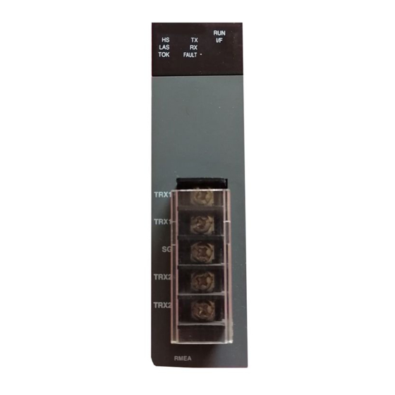
Page 18: Part Names And Structure
Chapter 2 Specifications 2.3 Part names and Structure 1) XBL-RMEA (1) LED display Status LED display description Normal Completion of initializing. Green Error Fatal error is occurred. Flickering Normal Normal status of interface in Main unit. Yellow Error Error status of interface in Main unit . Normal status of downloaded parameters from Normal XG5000 and High-speed link is normally... - Page 19 Chapter 2 Specifications 2) GOL-RR8T (1) LED Display SILK display LED Description Normal DC 24V power is connected normally. Error DC 24V power is not connected. LINK IN port is working normally Blink Normal (Rnet master must be connected to LINK IN.) LINK Error...
-
Page 20: Cable Specifications
Chapter 2 Specifications 2.4 Cable Specifications 1) Cable specifications - For fixed system Designations Type A Type B 135~160Ω(freq. 3~20MHz) 100~130Ω(freq. > 100kHz) Impedance Capacity < 30 pF/m < 60 pF/m < 110 Ω Resistance Conductor Area > 0.34 mm (22 AWG) >... - Page 21 Chapter 2 Specifications 2.5 Terminating Resistor 1) How to install terminating resistor Be sure to install the terminating resistor on the both ends of the line. (Rnet I/F module and last slave node) Connect Rnet I/F module with TRX2+ and TRX2- and Smart I/O Rnet module with TRX2+ and TRX2-. ...
-
Page 22: Chapter 3 Installation And Test Operation
Chapter 3 Installation and Test Operation Chapter 3 Installation and Test Operation 3.1 Installation 3.1.1 Precautions for installation For system configuration through Rnet Master I/F module, carefully make sure of the following items prior to installation. 1) Check the basic factors necessary for system configuration so to select an appropriate communication module. -
Page 23: From Setting To Operation
Chapter 3 Installation and Test Operation From Setting to Operation The sequence of the product from installation to operation will be described below. After the product installation is complete, install and configure the system to be operated as specified in the following sequence. -
Page 24: Chapter 4 System Configuration
Chapter 4 System Configuration Chapter 4 System Configuration 4.1 System with Rnet I/F module used Communication system between Rnet I/F modules can be configured as shown below. In order to connect with LS inverter, Rnet I/F option module shall be installed on the applicable product to make the communication available. -
Page 25: Mixed Configuration 2 Between Xbl-Rmea + Repeater + Rnet Slave
Chapter 4 System Configuration 4.1.3 Mixed configuration 2 between XBL-RMEA + repeater + Rnet slave... -
Page 26: Chapter 5 High-Speed Link Setting
Chapter 5 High-speed Link Setting Chapter 5 High-speed Link Setting 5.1 Introduction High-speed link specifies the Send/Receive device area and data size between CPU module and the communication module by XG5000. High-speed link can be set the function as shown below. Description High-speed Link Module type... -
Page 27: How To Use Xg5000
Chapter 5 High-speed Link Setting 5.2 How to use XG5000 XG5000 usage for Rnet I/F module is as shown below. XG5000 execution (1) I/O Sync Read Rnet I/F module information (a) Mode chage to stop (b) [Online] [Diagnosis] [I/O Info] (c) Clink I/O Sync (2) High-speed link setting 1) Connects High-speed link and Rnet I/F module. -
Page 28: High-Speed Link Editing
Chapter 5 High-speed Link Setting 5.3 High-speed Link Editing 5.3.1 Project screen XG5000 is executed as shown below. [Standard window] The parameter in XG5000 is as shown below. Basic setting High-speed link [Parameter window] Rnet I/F module is set in High-speed link window. It can use the High-speed link up to maximum 2. One High-speed link is available per one Rnet I/F module. - Page 29 Chapter 5 High-speed Link Setting 5.3.2 How to use High-speed link window Parameter is specified at High-speed link window as shown below. There are 2 kinds of parameter setting, Communication module setting and High-speed link block setting. High-speed link Parameter setting Communication module setting Select Click...
- Page 30 Chapter 5 High-speed Link Setting 1) Communication module setting parameter Communication module parameter setting is as shown below. Parameter Setting item Description Module type Rnet Communi- . Setting range: 0 note1 Base No cation Setting range: 1 ~ 11 module note1 Slot No It is different from type of main unit.
- Page 31 Chapter 5 High-speed Link Setting 2) Parameter of High-speed link block setting High-speed link block setting parameter is as shown below. (1) High-speed link editing window. Classification High-speed link block setting window Block editing Each entry of speed link setting windows is as follows. Classification Contents Index...
- Page 32 Chapter 5 High-speed Link Setting (2) High-speed link block editing Head address of Send/Receive address can be edited in High-speed block. Select index to edit and please set Read area & Save area. Classification Description Screen After If you complete setting uploaded about Read area and Save the data...
- Page 33 Chapter 5 High-speed Link Setting (3) How to use High-speed link block editing tool The editing tool and usage of High-speed link block is as shown below. Screen 1: Right mouse (right click) button of a selected area. Undo Undo edited index block. Redo Redo edited index block.
-
Page 34: Read And Write Of High-Speed Link
Chapter 5 High-speed Link Setting 5.4 Read and Write of High-speed Link The screen is used for read/write of High-speed link’s parameter. Configuration of menu Description 1) It can read for each High-speed parameter. - Select “Online” “Read” to read network parameter and program. - Page 35 Chapter 5 High-speed Link Setting Configuration of menu Description 1) It can read for each High-speed parameter. - Select “Online” “Write” to Write network parameter and program. Read/Write of High-speed link parameter not affect to CPU’s Run mode. If High-speed link parameter is written to CPU module, CPU module saves the data. If CPU module is exchanged, High-speed link parameter has to backup from CPU module.
-
Page 36: Enable Link
Chapter 5 High-speed Link Setting 5.5 Enable Link You need to enable the link for actual data communication of the downloaded HS link data. Configuration Description 1) Select “Online” “Enable Link” on the menu. Then, “Enable Link” screen appears. 2) Check the item you want to enable and click “Write”. -
Page 37: System Diagnosis
Chapter 5 High-speed Link Setting 5.6 System Diagnosis System diagnosis provides the information of Rnet Slave I/F module system. The System diagnosis screen is as shown below. Menu bar System diagnosis window Click right mouse button, then you can see the menu as below. It describes the menu of system diagnosis. - Page 38 Chapter 5 High-speed Link Setting Menu Screen configuration and description Base number of communication module which is connected with High- HS (High- Base no. speed link. Standard speed) link information Slot number of communication module which is connected with High- Slot no.
- Page 39 Chapter 5 High-speed Link Setting Menu Screen configuration and description Auto- Scanning Base no. Base number used for Rnet module Basic Info Slot no. Slot number used for Rnet module Link type Link type of Diagnosis I/F module. Station number of slave modules in same network with Rnet master Station no.
- Page 40 Chapter 5 High-speed Link Setting 5.7 High-speed Link Information High-speed link swaps the data between master module and all slave modules. It provides the flag of High-speed link operation status classified by individual station or total station. It is useful when checking the reliability of Transmission/Reception data and finding cause of error.
- Page 41 Chapter 5 High-speed Link Setting 1-3 Use flag by Normally Open Contact Use flag in ladder program 2-1 XG-5000 Monitor window Right Click Register in Variable/Comment Register in Variable/Comment Select PLC, Program 5-16...
- Page 42 Chapter 5 High-speed Link Setting Select Flags Select flag Flag type Select among the System/High-speed link/P2P/PID. List Select High-speed link It is showed the list of all High-speed links. Select list Parameter It means High-speed link number. The selected number number is only displayed in List.
- Page 43 Chapter 5 High-speed Link Setting Monitoring of flag and device’s value is as shown below. Flag monitor - Select variable in Variable/Comment screen and then Drag/Drop the variable to Variable Monitoring Window. The value is appeared in variable Monitoring Window. 5-18...
-
Page 44: Chapter 6 Communication Program
Chapter 6 Communication Program Chapter 6 Communication Program 6.1 Example Program Basic configuration of example and setting value is as shown below. Setting Classification Description phase Base No. Slot No. Station No. 0 (fixed) Communication 1Mbps (fixed) speed setting Communication 50ms period setting M100... - Page 45 Chapter 6 Communication Program Configuration of system...
- Page 46 Chapter 6 Communication Program XBL-RMEA(Rnet Master Module) Setting [ XG5000 1 phase ] Make a new project Menu : Project New Project Phase Item Screen configuration and setting description After typing Project name, select CPU series, CPU type. And then click OK Make a new project [ XG5000 2 phase] Connection setting between PC with CPU module...
- Page 47 Chapter 6 Communication Program [ XG5000 4 phase ] I/O Sync Menu : Online Diagnosis I/O Information Phase Item Screen configuration and setting description Online Change Mode Stop and then do I/O Sync I/O Sync [ XG5000 5 phase ] High-speed link setting Phase Item Screen configuration and setting description...
- Page 48 Chapter 6 Communication Program [ XG5000 6 phase ] Module type, Read area/Save area setting Phase Item Screen configuration and setting description Select send, receive mode Communication module setting High-speed link block after Read area/Save area setting [ XG5000 7 phase ] Write Network parameter Menu : Online ...
-
Page 49: Chapter 7 Troubleshooting
Chapter 7 Trouble shooting Chapter 7 Troubleshooting This chapter is to describe various errors that may occur in system operation, their causes and actions to take against. 7.1 Symptoms and Management by LED Status It shows the symptoms of communication module by LED status and the management. (When High-speed link is enabled) ○:LED Off, ◐: LED Flickering, ●: LED On LED status... -
Page 50: System Diagnosis In Xg5000
Chapter 7 Trouble shooting 7.2 System Diagnosis in XG5000 It shows the diagnosis item in XG5000. Diagnosis item Description Communication It displays the standard information of communication module. module information High-speed link It displays the flag information of High-speed link. [Table 7.2] System diagnosis in XG5000 It diagnoses the system by [Online] –... - Page 51 Chapter 7 Trouble shooting 7.2.2 High-speed link [Figure 7.2] High-speed link High-speed link diagnosis Classification Classification Description (Main item) (Sub item) Base no. Base number of attached module Slot no. Slot number of attached module Standard information Master station Master station number Communication method Slave’s communication method Normal: All station is a normal communication.
-
Page 52: Diagnosis Of Communication Module Through Xg5000
Chapter 7 Trouble shooting 7.3 Diagnosis of Communication Module through XG5000 It can monitor the communication status by XG5000. Connect to CPU port and [Online] – [PLC History] – [PLC Errors/Warnings]. [Figure 7.5] Detailed information of PLC history If hardware error or CPU interface error is occurred, communication module’s LED operates abnormally. -
Page 53: Trouble Shooting For Respective Error
Chapter 7 Trouble shooting 7.4 Trouble shooting for Respective Error 7.4.1 XG5000 abnormal connection XG-5000 abnormal connection Correct the serial cable’s port Communication serial port set correct? applicable to communication module. Close another program’s serial port. Another program using the communication serial port? Try again SyCon connection. -
Page 54: Communication Error With Master Module
Chapter 7 Trouble shooting 7.4.2 Communication error with Master module Communication error with Master module High-speed link’s Correct High-speed link’s parameters parameter set correctly? applicably to slave. (Refer to CH5) Any errors in communication Check power of communication modules. supply module? (Refer to Ch2.3) Slave station number duplicated? Correct slave station number. -
Page 55: Appendix
Appendix A.1 List of Flags A.1.1 Special register for data link [Table 1] List of communication flags based on HS link No. HS link No. 1 ~ 12 Keyword Type Detail Description Displays all stations normally operated as specified in HS link parameter, which will be On if 1.There is no RUN mode error in all stations specified in parameter... - Page 56 Appendix Note HS link No. L area address Notes L000500~L00099F Compared with HS link of 1 in [Table 1], other HS link station number’s L001000~L00149F flag address will be simply calculated as follows; L001500~L00199F L002000~L00249F Calculation formula: L002500~L00299F L003000~L00349F L area address = L000000 + 500 x (HS link No.
-
Page 57: Special Relays
Appendix A.1.2 Special relays Device 1 Device 2 Type Variable Function Description F0000 DWORD _SYS_STATE Mode & Status PLC mode & run status displayed. F00000 _RUN RUN status. F00001 _STOP STOP STOP status. F00002 _ERROR ERROR ERROR status. F00003 _DEBUG DEBUG DEBUG status. - Page 58 Appendix Device 1 Device 2 Type Variable Function Description DWORD _CNF_ER F0002 System error Serious error in system reported. F00020 _CPU_ER CPU error CPU configuration error found. F00021 _IO_TYER Module type error Module type is not identical. Module installation F00022 _IO_DEER90 Module is displaced.
- Page 59 Appendix Device 1 Device 2 Type Variable Function Description HS link – parameter 10 error F00051 _HS_WAR10 HS link 10 F00052 _HS_WAR11 HS link 11 HS link - parameter11 error F00053 _HS_WAR12 HS link 12 HS link - parameter12 error F00054 _P2P_WAR1 P2P parameter 1...
- Page 60 Appendix Device 1 Device 2 Type Variable Function Description F0011 WORD _LOGIC_RESULT Logic result Logic result displayed. F00110 _LER Calculation error ON for 1 scan if calculation in error. F00111 _ZERO Zero flag ON if calculation result is 0. F00112 _CARRY Carry flag ON if Carry found during calculation.
- Page 61 Appendix Device 1 Device 2 Type Variable Function Description F0050 WORD _SCAN_MAX Max. scan time Max. scan time displayed F0051 WORD _SCAN_MIN Min. scan time Min. scan time displayed F0052 WORD _SCAN_CUR Present scan time Present scan time displayed. PLC’s time information (Month/Year) F0053 WORD _MON_YEAR Month / Year...
- Page 62 Appendix Device 1 Device 2 Type Variable Function Description Slot number with discordant module type F0090 WORD _IO_TYER_N Discordant slot displayed. Slot number with displaced module F0091 WORD _IO_DEER_N Displaced slot displayed. F0092 WORD _FUSE_ER_N Fuse blown slot Slot number with fuse blown displayed. Slot number with module Read/Write F0093 WORD...
- Page 63 Appendix Device 1 Device 2 Type Variable Function Description F0127 WORD _IO_RWER7 Module RW 7 error Added base step 7 module Read/Write error F0128 WORD _IO_IFER_0 Module IF 0 error Main base module interface error F0129 WORD _IO_IFER_1 Module IF 1 error Added base step 1 module interface error F0130 WORD _IO_IFER_2...
- Page 64 Appendix Device 1 Device 2 Type Variable Function Description _USER_STAU F1025 WORD User contact point User contact point Initialization F10250 _INIT_DONE Initialization complete displayed. complete External serious Serious error information in external equipment F1026 WORD _ANC_ERR error information displayed. External slight Slight error information in external equipment F1027 WORD _ANC_WAR...
-
Page 65: Terminology
Appendix A.2 Terminology 1) Fieldbus Fieldbus is an industrial network system for real-time distributed control. It is a way to connect instruments in a manufacturing plant. Fieldbus works on a network structure which typically allows daisy-chain, star, ring, branch, and tree network topologies. Previously, computers were connected using RS-232 (serial connections) by which only two devices could communicate. - Page 66 Appendix 7) Smart I/O Smart I/O is a slave communication module including I/O function. Smart I/O is useful when you want to control long distance Digital I/O and analog I/O without no additional CPU and I/O modules. Therefore, Smart I/O can help you reduce installation and maintenance costs. It also provides open networks which are compatible with other manufacturer modules.
-
Page 67: External Dimensions
Appendix A.3 External Dimensions 1) XBL-RMEA Unit: mm 2) GOL-RR8T Unit: mm A-13... - Page 68 3. Since the above warranty is limited to PLC unit only, make sure to use the product considering the safety for system configuration or applications. Environmental Policy LS ELECTRIC Co., Ltd supports and observes the environmental policy as below. Environmental Management About Disposal LS ELECTRIC’...
- Page 69 ■ Headquarter ■ Overseas Subsidiaries • LS ELECTRIC Japan Co., Ltd. (Tokyo, Japan) LS-ro 127(Hogye-dong) Dongan-gu, Anyang-si, Gyeonggi-Do, 14119, Korea Tel: 81-3-6268-8241 E-Mail: jschuna@lselectric.biz • LS ELECTRIC (Dalian) Co., Ltd. (Dalian, China) ■ Seoul Office Tel: 86-411-8730-6495 E-Mail: jiheo@lselectric.com.cn •...
Need help?
Do you have a question about the XGT Series and is the answer not in the manual?
Questions and answers