LS ELECTRIC XGT Series User Manual
Pnet slave i/f module
Hide thumbs
Also See for XGT Series:
- User manual (1111 pages) ,
- Installation manual (2 pages) ,
- User manual (58 pages)
Table of Contents
Advertisement
Quick Links
Advertisement
Table of Contents
Troubleshooting

Related Manuals for LS ELECTRIC XGT Series


Summary of Contents for LS ELECTRIC XGT Series
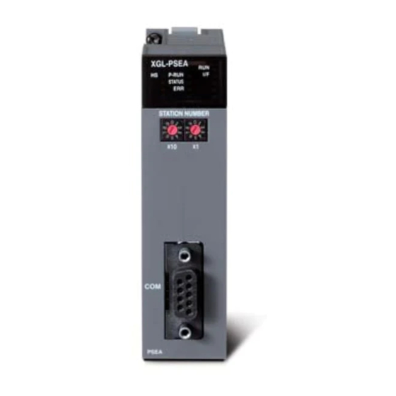
- Page 1 Programmable Logic Control Pnet Slave I/F Module XGT Series XGL-PSRA XGL-PSEA...
- Page 2 Safety Instruction Before using the product … For your safety and effective operation, please read the safety instructions thoroughly before using the product. ► Safety Instructions should always be observed in order to prevent accident or risk with the safe and proper use the product.
- Page 3 Safety Instruction Safety Instructions for design process Warning Please install a protection circuit on the exterior of PLC so that the whole system may operate safely regardless of failures from external power or PLC. Any abnormal output or operation from PLC may cause serious problems to safety in whole system. Install protection units on the exterior of PLC like an interlock circuit that deals with opposite operations such as emergency stop, protection circuit, and forward/reverse rotation or install an interlock circuit that deals with high/low limit under its position controls.
- Page 4 Safety Instruction Safety Instructions for design process Caution I/O signal or communication line shall be wired at least 100mm away from a high-voltage cable or power line. Fail to follow this instruction may cause malfunctions from noise Safety Instructions on installation process Caution ...
- Page 5 Safety Instruction Safety Instructions for wiring process Warning Prior to wiring works, make sure that every power is turned off. If not, electric shock or damage on the product may be caused. After wiring process is done, make sure that terminal covers are installed properly ...
- Page 6 Safety Instruction Safety Instructions for test-operation and maintenance Warning Don’t touch the terminal when powered. Electric shock or abnormal operation may occur. Prior to cleaning or tightening the terminal screws, let all the external power off including PLC power. If not, electric shock or abnormal operation may occur. ...
- Page 7 Safety Instruction Safety Instructions for waste disposal Caution Product or battery waste shall be processed as industrial waste. The waste may discharge toxic materials or explode itself.
- Page 8 5.5.2 ’14.09 XG5000 V4.0 UI Update V1.3 Format and contents modification according to the change of company name V1.4 ’20.05 (LSIS -> LS ELECTRIC) ’21.02 “Blank Module” related content added V1.5 4-15 ’21.12 Digital / Analog I/O module added V1.6...
- Page 9 About User’s Manual Thank you for purchasing PLC of LS ELECTRIC Co., Ltd. Before use, make sure to carefully read and understand the User’s Manual about the functions, performances, installation and programming of the product you purchased in order for correct use and importantly, let the end user and maintenance administrator to be provided with the User’s Manual.
-
Page 10: Table Of Contents
Table of Content ◎ Contents ◎ Chapter 1 Overview 1.1 How to use the user’s manual ................................1-1 1.2 Characteristics of Product ................................. 1-3 1.2.1 Characteristics of Pnet remote I/F module ..........................1-3 1.2.2 Characteristics of Pnet slave I/F module ..........................1-4 1.3 Product configuration .................................. - Page 11 Table of Content Chapter 4 Communication Programming 4.1 How to Set Master Module ................................4-1 4.1.1 High-speed Link ..................................4-1 4.1.2 XG5000’s Link Parameter Setting ............................4-2 4.1.3 High-speed Link communication status flag information (XGT) ..................4-4 4.2 How to register XGT Profibus-DP remote module ........................4-6 4.2.1 Create new project .................................
- Page 12 Table of Content Chapter 7 Maintenance and Repair 7.1 Repair and Check ................................... 7-1 7.2 Daily Check ...................................... 7-1 7.3 Regular Check ....................................7-2 Chapter 8 Trouble Shooting 8.1 Basic Procedure of Trouble Shooting ............................8-1 8.2 Trouble Shooting ..................................... 8-2 8.2.1 Action method when RUN LED is OFF ..........................
- Page 13 Table of Content...
-
Page 14: Chapter 1 Overview
Chapter 1 Overview Chapter 1 Overview 1.1 How to use the user’s manual This User’s Manual provides the information such as product specification, performance and operation method needed to use PLC System composed of Pnet remote I/F module. The User’s Manual is composed of as follows. CHAP.1 Overview Describes the configuration of the user’s manual, product characteristics and terminology CHAP.2 Product Specification... - Page 15 Chapter 1 Overview If you want to write programs, refer to the following manuals. • GLOFA PLC Instruction manual • GLOFA PLC GMWIN user manual • GLOFA PLC GM3/4 user manual • GLOFA PLC GM6 user manual • MASTER-K Instruction •...
-
Page 16: Characteristics Of Product
Chapter 1 Overview 1.2 Characteristics of Product 1.2.1 Characteristics of Pnet remote I/F module The characteristics of Pnet remote I/F module are as follows. (1) Product design based on International Electrotechnical Commission (IEC 61131) (GLOFA series in common) Easy support to programming device ... -
Page 17: Characteristics Of Pnet Slave I/F Module
Chapter 1 Overview 1.2.2 Characteristics of Pnet slave I/F module The characteristics of Pnet slave I/F module are as follows. (1) Supports open network by adopting a communication protocol of international standard. (2) Available to communicate with the master module at long distance (3) Available to set up to 98 stations (4) Helpful in reducing installation and maintenance cost (5) Diverse system configuration and easy maintenance... -
Page 18: Product Configuration
Chapter 1 Overview 1.3 Product configuration 1.3.1 Product configuration of the Pnet remote I/F module Digital I/O module Name Model Contents Remark • DC 24V input, 8 points (current source / sink input) XGI-D21A • DC 24V Diagnosis input, 8 points (Current source / sink input) Note1) XGI-D21D •... - Page 19 Chapter 1 Overview Analog I/O module Name Model Contents Remark • Voltage input: 4 channels XGF-AV4A • Voltage input: 8 channels XGF-AV8A • Current input: 4 channels XGF-AC4A • Current input: 8 channels XGF-AC8A • Voltage/Current input: 8 channels XGF-AD8A Analog input •...
-
Page 20: Product Configuration Of The Pnet Slave I/F Module
Chapter 1 Overview 1.3.2 Product Configuration of the Pnet slave I/F module System configuration of the Pnet slave module note1) note2) Available CPU Installation position Max. installation numbers Remark XGI-CPUU/CPUH Main base ~ expansion 7 XGI-CPUS Main base ~ expansion 3 XGI-CPUE Main base ~ expansion 1 XGK-CPUU/CPUH... -
Page 21: Software To Use The Product
Chapter 1 Overview 1.4 Software to use the product Here describe on main programming tool and other software to use the Pnet slave I/F module. For more specific program and application of communication, refer to the followings. 1.4.1 Software check point Classification Product Communication setting tool... -
Page 22: Check Of Version
Chapter 1 Overview 1.4.3 Check of version Before using the Pnet slave I/F module, check the version of module. (1) Check through XG5000 Here describes on how to read communication module information by online connection to communication module. If interface with CPU is normal, it is available to get the following information. (a) Execute the XG5000. -
Page 23: Version Compatibility List
1.5 Version Compatibility List 1.5.1 Pnet Remote I/F Module Compatibility List The following table indicates compatible list of LS ELECTRIC Profibus-DP master module to use Pnet remote I/F module. Before applying the system, refer to the following list. Available Module Classification Ref. -
Page 24: Notice In Using
Chapter 1 Overview 1.6 Notice in Using When installing this device, notice the followings for the reliability and safety. Category Classification Contents • When installing this device, maintain the temperature between 0~55 °C Condition • Do not exposure it to direct light. Temperature •... - Page 25 Chapter 1 Overview 1-12...
-
Page 26: Chapter 2 Product Specification
Peak acceleration: 147 m/s (15G) Shock Duration: 11ms IEC61131-2 resistance Half-sine, 3 times each direction per each axis AC: 1,500V Square wave LS ELECTRIC DC: 900V Impulse noise standard Electrostatic IEC61131-2 4.0kV (Contact discharge) discharge IEC61000-4-2 Radiated... -
Page 27: Communication Module Specification
Chapter 2 Product Specification 2.2 Communication Module Specification 2.2.1 Pnet remote I/F module specification Item Specification Standard EN50170 / DIN 19245 Interface RS-485(electric) Media access Polling Topology Bus method Modulation method Communication interface Auto baud rate Master/Slave Slave Max. station count per network 100 stations (including master and repeater) Max. -
Page 28: Pnet Slave I/F Module Specification
Chapter 2 Product Specification 2.2.2 Pnet slave I/F module specification Item Specification Standard EN50170 / DIN 19245 Interface RS-485(electric) Media access Polling Topology Bus method Modulation method Communication interface Auto baud rate Master/Slave Slave Max. station count per network 99 stations (including master and repeater) Max. -
Page 29: Communication Cable Specification
Chapter 2 Product Specification 2.3 Communication Cable Specification 2.3.1 Profibus-DP cable specification Cable specification Classification Contents BELDEN cable:: Product name : 3077F, 3079A Cable Tomas cable : Product name : Profibus-DP UNITRONIC-BUS L2/FIP/BUS Type BC (Bare copper) Insulation PE (Polyethylene) Insulation 0.035 (inch) -
Page 30: Terminating
Chapter 2 Product Specification 2.4 Terminating 2.4.1 Pnet Terminating Connection Connector Cable connection unit Terminating switch A1 B1 A2 B2 A1 B1 A2 B2 ON : termination OFF: No termination <Terminal connection> <Branch connection>... - Page 31 Chapter 2 Product Specification...
-
Page 32: Chapter 3 System Configuration
Chapter 3 System Configuration Chapter 3 System Configuration This chapter describes the method of system configuration and characteristics. 3.1 Notices in Selecting Module Here describes the notices in selecting digital I/O module which is used for Remote I/O. 1) Digital input types contain the current sink input and current source input In case of DC input module, as the wiring method of external input power is different according to such input types, make sure of selecting the input module considering the spec. -
Page 33: Names Of Each Part (Pnet Remote I/F Module)
Chapter 3 System Configuration 3.2 Names of Each Part ( Pnet Remote I/F module) 3.2.1 Basic System Configuration Communicates with master and controls expansion I/O module through Backplane Bus Pnet …… master Profibus-DP communication Backplane bus Pnet remote DI/DO DI/DO DI/DO DI/DO AI/AO AI/AO AI/AO AI/AO DI/DO DI/DO DI/DO AI/AO module SLOT... - Page 34 Chapter 3 System Configuration Item Name Normal Abnormal LED indication contents Module normal (Normal operation of system O/S) O/S is not operating (O/S operation error by H/W error) Pnet communication normal P-RUN Not connected with master or not communicating with master System configuration of master is same as I/O configuration of slave so communication is normal...
-
Page 35: Available Product List
Chapter 3 System Configuration 3.2.3 Available Product List Power module list Model Specification XGP-ACF1 AC100V - AC240V, 3A XGP-ACF2 AC100V - AC240V, 6A XGP-AC23 AC200V - AC240V, 8.5A XGP-DC42 DC24V, 6A Base list Model Specification Remark XGB-M04A 4-slot main base ※... - Page 36 Chapter 3 System Configuration Analog module list XGF-AV4A Voltage input: 4 channels XGF-AV8A Voltage input: 8 channels XGF-AC4A Current input: 4 channels XGF-AC8A Current input: 8 channels XGF-AD8A Voltage/current input: 8 channels Analog input XGF-AD4S Voltage/current input: 4 channels, insulation between channels Voltage/current input: 4 channels(2-wire input), XGF-AW4S insulation between channels...
-
Page 37: Names Of Each Part (Pnet Slave I/F Module)
Chapter 3 System Configuration 3.3 Names of Each Part ( Pnet Slave I/F module) 3.3.1 Basic System Configuration Communicates with master and controls expansion I/O module through CPU Pnet …… Master Profibus-DP communication Pnet slave DI/DO DI/DO DI/DO AI/AO AI/AO AI/AO AI/AO DI/DO DI/DO DI/DO AI/AO module SLOT... - Page 38 Chapter 3 System Configuration 2) LED Item Name Normal Abnormal LED indication contents Initialization complete and normal operation (Normal operation of system O/S) Heavy trouble (O/S operation error by H/W error) Master configuration and slave parameter are identical and data communication is normal P-RUN Data communication between the master and the slave is not being executed.
-
Page 39: System Configuration Example
Chapter 3 System Configuration 3.4 System Configuration Example 3.4.1 Pnet System (GMWIN) Pnet remote module XGL-PSRA Other company PLC Load Load Load Load... -
Page 40: Pnet System (Xg5000)
Chapter 3 System Configuration 3.4.2 Pnet system (XG5000) Pnet remote module XGL-PSRA Other company PLC Load Load Load... - Page 41 Chapter 3 System Configuration 3-10...
-
Page 42: Chapter 4 Communication Programming
Chapter 4 Communication Programming Chapter 4 Communication Programming 4.1 How to Set Master Module Describes how to set master module to use Pnet remote module For more detail, refer to master module’s user manual. 4.1.1 High-speed Link High-speed Link is used when other station’s data or information is periodically exchanged at every specific time. By referring to the changing data of its own station or other station periodically, it enables to utilize the data to the system effectively and communicates by setting the simple parameter. -
Page 43: Xg5000'S Link Parameter Setting
Chapter 4 Communication Programming 4.1.2 XG5000’s Link Parameter Setting When using XGT Pnet master module, it is easy to set device region and date size to communicate between CPU module and Communication module (Master module and Slave module) by using XG5000. (1) Pnet High-speed Link setting Contents Contents High-speed Link... - Page 44 Chapter 4 Communication Programming (2) How to use XG5000 How to use XG5000 for Pnet I/F Module is as follows. Execute XG5000 Read information of Pnet I/F module (a) Read I/O Information (b) High-speed Link Setting 1) Comnication module setting 1) Connect Pnet I/F module read from I/O information a) Comnication module setting: Pnet with High-speed Link.
-
Page 45: High-Speed Link Communication Status Flag Information (Xgt)
Chapter 4 Communication Programming 4.1.3 High-speed Link communication status flag information (XGT) Communication Flag List corresponding to High-speed Link Number High-speed Link No.1~12. Keyword Type Contents Contents Explanation It indicates normal status of all stations which operate according to parameter set in the High-speed Link. If the following condition is met, It would be turned On. - Page 46 Chapter 4 Communication Programming Note High-speed L Region Link Reference Address Number Number L000500~L00099F When [Table 1]’s High-speed Link is 1, other Flag address number is as follows according to simple calculation. L001000~L00149F L001500~L00199F ∗Calculation: L region address number = L000000 + 500 X (High-speed Link L002000~L00249F Number-1) L002500~L00299F...
-
Page 47: How To Register Xgt Profibus-Dp Remote Module
Chapter 4 Communication Programming 4.2 How to register XGT Profibus-DP remote module In order to use XGT Profibus-DP remote module, you have to register an extended module parameter by using Extended Adapter. 4.2.1 Create new project Select “File – New File” and then select “XGL-PSRA” at Adapter type. After connecting USB cable to XGT Profibus-DP remote module, turn on the power. -
Page 48: Set Io Parameter
Chapter 4 Communication Programming 4.2.2 Set IO parameter If I/O parameter is different with actual system configuration in main base, XGT Profibus-DP remote module indicates “Module type mismatch” error. At this time, STATUS LED is off. I/O synchronization Open “I/O information” at “Online” and check whether I/O information matches actual system configuration. The following figure is I/O information where TR output modules are in slot 0 and 1, XGF-DV8A in slot 2, XGF- AD4S in slot 3. - Page 49 Chapter 4 Communication Programming If I/O information matches actual module configuration, click “I/O synchronization button” and match I/O information. If “module mismatch error” appears, check whether ERR LED is off or not. Check whether all modules are registered at project window. Analog module parameter setting To set a detail parameter on the module, double-click the module at project window.
- Page 50 Chapter 4 Communication Programming Digital I/O module parameter setting If you double-click the digital I/O module, for output module, emergency output setting window appears and for input module, input filter setting window appears as follows. Emergency output sets output status in case of remote module error. If emergency output is “Clear”, output becomes ‘0’...
- Page 51 Chapter 4 Communication Programming Write parameter After completing the parameter setting, download parameter through “Online – Write Parameter”. If downloading is complete, complete message appears. Note 1) Parameter is saved in flash memory permanently. 2) Emergency parameter is applied when communication with master is not normal. 3) Emergency output data is not maintained when power is off.
-
Page 52: How To Set Pnet Slave I/F Module Parameter
Chapter 4 Communication Programming 4.3 How to set Pnet slave I/F module parameter In order to use the XGT Profibus-DP slave module, you have to register high-speed link parameter by using XG5000. 4.3.1 High–Speed link parameter setting Execute the XG5000 and create new project After selecting CPU type, click the right mouse button while cursor is on the base where Pnet slave is installed and set communication module as follows. - Page 53 Chapter 4 Communication Programming In the project window, select High-speed link tap and High speed link. Set the module type as “Pnet Slave” and set “Communication period” and “Output data setup in case of emergency” [Figure 4.3.3] Communication module settings Select a High-speed link block and set up TX, RX items The following figure is block setup transmitting 2-word data of M0000 and receiving 2-word data of M0100.
-
Page 54: High-Speed Link Communication Diagnosis
Chapter 4 Communication Programming 4.3.2 High-speed Link Communication Diagnosis You can check the data communication status through the LED in the communication module When you want to monitor detailed High-speed link data for each block, monitor the High-speed link service at the system monitor window. -
Page 55: Sycon Parameter Setting
Chapter 4 Communication Programming 4.3.3 Sycon Parameter Setting Describes how to set up the parameter of the slave module with SyCon 1) Module parameter setting Double-click the slave station at the main screen of SyCon as follows. Configuration window of the slave station appears as follows. Select the module in the middle box and click “Append Module”... - Page 56 Chapter 4 Communication Programming Note If there is empty slot in XGL-PSRA, [Blank Module] should be added at that location. 4-15...
- Page 57 Chapter 4 Communication Programming 2) Slave parameter setting In order to set up the parameter of the slave station, click “Parameter Data” at the configuration window. Then “Parameter Data” window appears Parameter data consists of 6-byte data. Click “Common” button to check the meaning of the each parameter item 0~2-byte are parameter on DPV1.
- Page 58 Chapter 4 Communication Programming Diagnostic parameter is the parameter on enabling diagnostic function. If you set this as “Enable”, when operation mode of the CPU module where slave station is installed is not “Run” or CPU module is error state, you can monitor CPU module status at the master station.
- Page 59 Chapter 4 Communication Programming Diagnostic information window of the slave station appears and informs that “Extended Diagnostic” occurs If you click “Ext. Diagnostic” button, detailed information of the slave station appears as follows. The following detailed information window informs that the CPU module where slave station is installed is “Stop” state.
- Page 60 Chapter 4 Communication Programming "I/O parameter error " "Special module parameter error " "Special module parameter error " "Program error " "Program code error " "System watchdog error " "Base power error " "Scan watchdog error " "Base information error " "Timer index error "...
- Page 61 Chapter 4 Communication Programming 4-20...
-
Page 62: Chapter 5 Profibus-Dp Communication
Chapter 5 Profibus-DP Communication Chapter 5 Profibus-DP Communication 5.1 Overview Profibus is an open type field bus that the manufacturer selects independently to apply and manufacture (Vendor-independence). Also, It is used widely for processing automation. DP among them is the most frequently used Communication profile and the network suitable for FA environment of Field Level and also is suitable for master-slave communication between master automation machine and distribution slave I/O machine. -
Page 63: Basic Performance
Profibus-DP Master module is available to set as the following function. (1) Supports only High-speed Link communication. (2) Uses parameter setting in GMWIN/KGLWIN/XG5000 and Configuration Tool (LS ELECTRIC provided tool : SyCon, N Configurator). (3) Sets only sending/receiving area from GMWIN/KGLWIN/XG5000 high-speed link parameter setting. -
Page 64: Procedure To Establish Pnet Communication
Chapter 5 Profibus-DP Communication 5.3.3 Procedure to establish Pnet communication Master communicates Pnet expansion I/O module based on the downloaded setting information After writing parameter and checking, I/O data communication starts. If it fails when processing each step, diagnosis is executed. Initial sequence operation to establish communication is as follows. -
Page 65: I/O Data Communication
Chapter 5 Profibus-DP Communication 5.3.4 I/O Data Communication Expansion I/O modules are communicates with master by using backplane bus. Max. TRX data is 244 byte. XGL-PMEA, PMEC, Hneywell master (PMD Master) Pnet …… Input data master Output data Pnet remote module SLOT Backplane Bus... - Page 66 Chapter 5 Profibus-DP Communication 3) Slave I/F module refreshes data in TRX buffer through CPU module’s I/O image area and CPU module refreshes data in I/O image area through I/O module and backplane bus. XGL - PMEA , PMEC Pnet ……...
-
Page 67: Tool For Communication Setting
If using master module provided by LS ELECTRIC (G3/4/6L-PUEA/PUEB, XGL-PMEA), it is required to configure Profibus Network using SyCon and download the information to the corresponding master module. As Profibus Network Configuration Tool is different from each master module, if using LS ELECTRIC master module (G3/4/6L- PUEA/PUEB,XGL-PMEA), it is required to use only SyCon. - Page 68 Chapter 5 Profibus-DP Communication Insert the master at the top of window below If Insert Master window is open as the above figure, select COM-DPM/PKV20-DPM if the using master module is G3/4/6L-PUEA and click Add button in the middle. If using master module is G3/4/6L-PUEB, select COM- PB/PKV20-PB and click Add button in the middle.
- Page 69 Chapter 5 Profibus-DP Communication Master module setting If you click the right side of mouse on the inserted master module and select “Master Settings...” from the appeared popup window, the following window will be open. Select “Controlled release of the communication by the application program”...
- Page 70 Chapter 5 Profibus-DP Communication If using XGL-PSRA, select “XGL-PSRA” from the left side “Available slaves” and click “Add” button in the middle part. If there are several masters, select one from the right side “Master” and confirm “Station address” and “Description”, and then click “OK”...
- Page 71 Chapter 5 Profibus-DP Communication Slave Configuration Click the inserted slave icon with the right button of mouse and select “Slave configuration” from the appeared popup window. (or double-click the left button of mouse on the slave icon.) List box in the middle part shows all available modules. If you select the module having the necessary point and click “Append Module”...
- Page 72 Chapter 5 Profibus-DP Communication Device Allocation It is required to download the prepared configuration to the master module. In this case, click the left button of mouse and select master module icon to set which device to use. Select “Setting/Device Assignment...” from the menu. (1) Device Allocation (2) Driver Selection If driver selection window is open, select “CIF Serial Driver”.
- Page 73 Chapter 5 Profibus-DP Communication (3) Driver Selection of CIF Serial Driver ① Press the button “Connect ② If the corresponding COM1” to confirm if the module information is corresponding module indicated, check the information is indicated. “COM1” check box. ③ If everything ends normally without any error, press “OK”...
- Page 74 Chapter 5 Profibus-DP Communication Configuration Download If you select “Online/Download” from the menu, ‘Download’ begins to run. In this case, all LED shall be OFF and only “READY” LED shall be blinking. After downloading, all LED show its function. If you carry out ‘Download’ in the status that the communication between the current master and slave is open, the warning window with the message “if the download is done during the bus operation, the communication between the master and the slaves is stopped.”...
- Page 75 Chapter 5 Profibus-DP Communication 5.4.2 Communication Setting through N Configurator If you use LS ELECTRIC’s master module (XGL-PMEB), you can configure Profibus Network and download it by using N Configurator. Screen of N Configurator is as follows. Project explorer Device list...
- Page 76 Chapter 5 Profibus-DP Communication Master configuration There are master devices at the top of the device list. Select the master you want use as figure below. If you want to change the properties of master such as station number or description, press ““Master Properties” of “Configuration”...
- Page 77 Chapter 5 Profibus-DP Communication Slave configuration Slave configuration is available after master configuration. How to configure slave is same as that of master. Select the slave device you want to add in the device list as figure below. Basically the tool allocates station number in order when adding each device to topology. So if you want to change station number and properties of slave, user “Slave Properties”...
- Page 78 Chapter 5 Profibus-DP Communication For user parameter setting, “Slave Parameter Settings” window appears as figure below. 5-17...
- Page 79 Chapter 5 Profibus-DP Communication “Slave Module Settings” window is as follows. Double-click the actually configured module in the Module Selection area. If you select wrong module, double-click the module then the module is removed. 5-18...
- Page 80 Chapter 5 Profibus-DP Communication Bus parameter You can change the communication speed or communication parameter through network bus parameter setting. Generally, default value of communication parameter is used so we describe how to change communication speed. Since the master has the right to change network bus parameter, you should select the master in the topology. Then “Bus Parameters”...
- Page 81 Chapter 5 Profibus-DP Communication Configuration download and upload PROFIBUS DP master operates based on Network configuration data. For this, you should download the network configuration data to master. And you can read the downloaded configuration data from master (Upload function). Here Pnet I/F module of XGT PLC, XGL-PMEC is used for example.
- Page 82 Chapter 5 Profibus-DP Communication (2) Network Configuration download After configuring network in the topology, if you select “Download Image” item of “Communication” menu, downloading will start. The figure below displays downloading status. Progress Bar operates in the status bar and Process Rate is displayed in the output window.
- Page 83 Chapter 5 Profibus-DP Communication (3) Network Configuration upload If you select “Upload Image” item of “Communication” menu, uploading will starts. At this time, project is created automatically. If uploading is complete, “Done” is displayed in the output window and Network Configuration read form master is displayed in the project topology window.
-
Page 84: High Speed Link Setting
Chapter 5 Profibus-DP Communication 5.5 High Speed Link Setting 5.5.1 High Speed Link Setting in GMWIN In the previous article, we explained the method to set Configuration and the method to download this to the master module. High-speed Link parameter setting should be done after downloading Configuration. And High-speed Link parameter is set by selecting link parameter from GMWIN project screen and setting the corresponding items. - Page 85 Chapter 5 Profibus-DP Communication 2) Link parameter setting If you select the corresponding parameter from parameter setting basic screen, the High-speed Link parameter setting initial screen will appear as shown in the following figure. Parameter setting initial screen is composed of two items such as ‘link set’ and ‘Entry list’. The setting method per each item and its function are as follows 3) High-speed Link setting “Link Set”...
- Page 86 Chapter 5 Profibus-DP Communication ● Network Type: It sets the installed communication module type and GLOFA Pnet should be set. ● Slot Num: It sets the position of the communication module. (0 ~ 7 slot). ● Self-station Num: The master module’ station no. shall be set in SyCon and the slave module’s station no. shall be set by rotary switch.
- Page 87 Chapter 5 Profibus-DP Communication Remark 1) The size of receive/transmit area is total I/O contact number made in SyCon. 2) The order of module is as follows. First, G4L-PUEA 1 and GPL-TR2A (16 points), GPL-TR4A (32 points), GPL-D22A (16 points) and when setting the transmit area as %MW0, the receiving area as %MW100, - Transmit area : %MW0 - Receive area : %MW100...
- Page 88 Chapter 5 Profibus-DP Communication Example of High-speed Link parameter setting of each station Station 1 Station 2 Station 3 Station 4 Station 5 send: 2 words sending: 2words sending: 2words receive: 2words receiving: 2words receiving: 2words (station 2) (station 1) (station 1) sending: 2words sending: 2words...
- Page 89 Chapter 5 Profibus-DP Communication High-speed Link information monitor screen (Variable registration) 5-28...
- Page 90 Chapter 5 Profibus-DP Communication (2) Link parameter monitor If you select ‘link parameter’ item from monitor menu of GMWIN online connection, ‘Select Link Parameter’ screen will appear as shown on the figure below. If the user selects the desired item from parameter number set by it and verify it, the High-speed Link parameter monitor screen will be open and the setting registration list will be monitored and indicated on the screen.
-
Page 91: High-Speed Link Parameter Setting In Kglwin
Chapter 5 Profibus-DP Communication 5.5.2 High-speed Link Parameter Setting in KGLWIN Profibus-DP master for MASTER-K also uses SyCon for the Configuration setting and the setting method is the same as that of GLOFA-GM. In case of MASTER-K, it should be required to set the High-speed Link parameter after downloading the Configuration to the master module and the High-speed Link parameter selects the parameter from KGLWIN project screen and set the corresponding item. - Page 92 Chapter 5 Profibus-DP Communication The High-speed Link item tab of the above figure means max. installation number of communication module according to PLC CPU type. The High-speed Link button as much as the available setting number shall be active and in this case, the High-speed Link no. is not related to the installed slot no. and the slot no. shall be set in the individual parameter setting screen and only one High-speed Link parameter is available to set for one communication module.
- Page 93 Chapter 5 Profibus-DP Communication Remark 1) The size of sending/receiving area is the total I/O contact number made in SyCon. 2) The order of setting is carried out as G4L-PUEA 1 and GPL-TR2A(16 points), GPL-TR4A(32 points), GPL-D22A(16 points) and when setting sending area as P000, the receiving area as P010, Sending area : P000 Receiving area : P010 Size of sending area : 6 bytes(total output contact number)
-
Page 94: High Speed Link Setting In Xg5000
Chapter 5 Profibus-DP Communication 5.5.3 High Speed Link Setting in XG5000 Operation sequence of High-speed link S/W applied Operation Details Execute XG5000 XG5000 File New File Set project name and type Create new file Set XG5000 connection XG5000Online connection settings XG5000... - Page 95 Chapter 5 Profibus-DP Communication High Speed Link Parameter Setting High-speed link parameter setting is set in High-speed link screen in XG5000. Sequence of settings, please refer to the Chapter 8.3. (1) Execution of XG5000 and creation of new file XG5000 is executed firstly Basic screen of XG5000 Item Contents...
- Page 96 Chapter 5 Profibus-DP Communication Items Description Connection method RS-232C, USB Connection Local/Remote connection setting option settings Connection steps Local: Connection of from PC to CPU Remote: Connection from PC to CPU via communication module Timeout time when 1~9 seconds communication failure Common Retried number when 1~9 times...
- Page 97 Chapter 5 Profibus-DP Communication (6) Communication module and Communication period setting If double-click the High-speed link, screen of Communication module settings and Communication cycle settings is opened. In this screen, communication module, communication and Output data setup in case of emergency settings period can be specified.
- Page 98 Chapter 5 Profibus-DP Communication (7) Config. Upload After “Setting of communication module and communication period” is complete, click the mouse cursor positioned on High-speed link window (right screen of XG5000), and select “Online” “Communication module setting” “Config. Upload (Dnet, Pnet)” to upload SyCon’s configuration file. (8) Setting of High-speed link block Double-click the applicable index number of Configuration file uploaded and designates the ‘Read area’...
- Page 99 Chapter 5 Profibus-DP Communication (9) Write the High-speed link parameter Click “Online” “Write” in XG5000, check the applicable High-speed link and then click [OK]. Screen of Write the parameter 5-38...
- Page 100 Chapter 5 Profibus-DP Communication (10) Enable of High-speed link Click “Online” “Link Enable” in XG5000, check the applicable High-speed link and then click [Write]. If High- speed link is enabled, on the module’s LED display High-speed LED will be On, when High-speed link starts. Screen of Link Enable 5-39...
- Page 101 Chapter 5 Profibus-DP Communication * Enable Link through flag It describes “Enable Link” method through flag. The following XG5000 version, CPU OS version is needed. Item Version XG5000 V3.61 or above XGR CPU V1.91 or above XGI CPU V3.4 or above XGK CPU V3.7 or above Flag list related with “Enable Link”...
- Page 102 Chapter 5 Profibus-DP Communication Flag Data type Device Description _HS8_REQ F10307 HS link 8 enable/disable request _HS9_REQ F10308 HS link 9 enable/disable request _HS10_REQ F10309 HS link 10 enable/disable request _HS11_REQ F1030A HS link 11 enable/disable request _HS12_REQ F1030B HS link 12 enable/disable request _HS1_REQ_NUM F10310 HS link 1 enable/disable setting...
-
Page 103: How To Set Gsd And Downloading Procedure
Chapter 5 Profibus-DP Communication 5.5.4 How to set GSD and downloading procedure Download expansion I/O module and Pnet remote I/O module information through GSD file Read the GSD file where information of our digital or analog I/O module is descried through the configuration tool supporting Pnet configuration The user can modify the parameter through configuration tool. -
Page 104: Chapter 6 Installation And Wiring
Chapter 6 Installation and Wiring Chapter 6 Installation and Wiring 6.1 Installation 6.1.1 Installation Environment This machine has a high reliability regardless of the environment to install. But cares should be taken to secure the reliability and the safety as follows. 1) Environment Condition (1) Install it to a water-proof and dust-proof control panel. -
Page 105: Notices In Installing Profibus-Dp Module
Chapter 6 Installation and Wiring 6.1.2 Notices in installing Profibus-DP module Profibus-DP Smart I/O can set max. 126 stations. (including master) But forXGL-PSRA, station number 0~99 is available. For XGL-PSEA, station number 0~98 is available (1) Check the basic factors necessary for the system configuration and select the proper communication module. (2) Prepare the cable and accessories such as tab, terminal resistance etc. -
Page 106: Notices In Handling
Chapter 6 Installation and Wiring 6.1.3 Notices in Handling Here it describes notices in handling from the opening of each unit and module to the installation. Do not drop or apply the strong impact. Do not remove the PCB from the case. It may cause failure. ... - Page 107 Chapter 6 Installation and Wiring In case the inductive load is connected to the output part, please connect the surge killer or diode to the load in parallel. Connect the cathode of diode to the ‘+’ side of the power. Induction load Output Surge killer...
- Page 108 Chapter 6 Installation and Wiring 2) Notices in installation Here it describes the notices in attaching the PLC to the control panel. (1) Sufficient distance is required to have well-ventilated room and facilitate the exchange of the basic unit and the extended module.
- Page 109 Chapter 6 Installation and Wiring (5) In case the equipment is installed in front of the PLC (inside the door) to avoid the effect of radiant noise or the heat, it is required to separate it more than 100mm and be install. And the left/right direction of the unit and the equipment should be separated more than 100mm and installed.
-
Page 110: Wiring
Chapter 6 Installation and Wiring 6.2 Wiring Describes the notices related to the wiring in case of using the system 6.2.1 Power Wiring 1) For power, please use AC100~240V power supply. 2) If the power variation is larger than the regular range, please connect a constant voltage transformer. 3) In order to prevent the noise from the power cable, it is required to twist the power cable densely if possible, and connect within the shortest distance. - Page 111 Chapter 6 Installation and Wiring 6) For the power cable, it is required to use a thick one (2mm ) to make the small falling down of the voltage. 7) The power cable is not allowed to approach closely to the main circuit (high voltage, convection current) cable, I/O signal cable and needs to separate more than 80mm apart.
-
Page 112: I/O Device Wiring
Chapter 6 Installation and Wiring 6.2.2 I/O Device Wiring 1) The spec. of I/O wiring cable is 0.18~2 mm and it is recommended to use the cable spec. (0.5mm ) conveniently. 2) Input cable and output cable should be separated for wiring. 3) I/O signal cable should be separated at least 80mm from main circuit cable of high voltage, high current when wiring. -
Page 113: Cable Specification For Wiring
Chapter 6 Installation and Wiring 4) Please use the electric wire for grounding more than 2 mm . Place the grounding point near this PLC if possible and shorten the length of the grounding cable. When connecting the extended base, please connect the extended connector accurately. ... -
Page 114: Chapter 7 Maintenance And Repair
Chapter 7 Maintenance and Repair Chapter 7 Maintenance and Repair To maintain the PLC in optimal status, please carry out daily check and regular check. 7.1 Repair and Check I/O module is usually composed of semiconductor microelectronic device and the life is semi- permanent. As the microelectronic device may occur the error caused by the ambient environment, it is required to check it periodically. -
Page 115: Regular Check
Chapter 7 Maintenance and Repair 7.3 Regular Check Check the following items 1~2 times every 6 months and take the necessary actions. Checking items Checking method Judgment basis Action 0 ~ 55℃ Temperature Adjust suitable for general Measure by Ambient thermometer/hygrometer. -
Page 116: Chapter 8 Trouble Shooting
Chapter 8 Trouble Shooting Chapter 8 Trouble Shooting Here it describes the contents of each error to be occurred while operating the system, the method to find the cause and the action. 8.1 Basic Procedure of Trouble Shooting It is important to use high reliable machine to increase the system reliability but it is important to take prompt action when trouble occurs as well. -
Page 117: Trouble Shooting
Chapter 8 Trouble Shooting 8.2 Trouble Shooting Here it describes the trouble finding method, the error code and the actions on the above by dividing them per phenomenon. Description of Trouble Action method when POWER LED is OFF. When POWER LED is Action method when ERR LED is on. -
Page 118: Action Method When Run Led Is Off
Chapter 8 Trouble Shooting 8.2.1 Action method when RUN LED is OFF Here it describes the action order when RUN LED is OFF while applying the power or during the operation. RUN LED is OFF Supply the power. Is the power being supplied? Is RUN LED ‘ON’? Meet the supply power within the Is the power voltage within... -
Page 119: Action Method When Err Led Is On
Chapter 8 Trouble Shooting 8.2.2 Action method when ERR LED is ON Here it describes the action order when ERR LED is on in case of power input, or when operation starts, or during operation. ERR LED is on Connect expansion adapter program and check the error code contents. -
Page 120: Action Method When I/O Part Does Not Work Normally
Chapter 8 Trouble Shooting 8.2.3 Action method when I/O part does not work normally. Here it describes the action order when I/O part does not work normally during operation, as shown on the program example below. When I/O part does not work normally, Is output LED of SOL1 ‘ON’? Measure SOL1 terminal... - Page 121 Chapter 8 Trouble Shooting Continue Is SWITCH1, 2 LED ‘ON’? Measure terminal Measure terminal voltage of SWITCH1, 2 by voltage of SWITCH1, 2 by the tester. the tester. Is the tightening status of Is the measured value Is the measured value terminal good? normal? normal?
-
Page 122: Action Method When Program Write Does Not Work
Chapter 8 Trouble Shooting 8.2.4 Action method when Program Write does not work Here it describes the action order when Program write does not work in the Master CPU. Program write does not work Put the key switch to remote STOP mode and run Program Is the key switch set as remote Write. -
Page 123: Sycon Connection Error
Chapter 8 Trouble Shooting 8.2.5 SyCon connection error SyCon connection error Set serial port properly Is serial port set properly? Close other program which is Is each serial port used by using serial port and try to other program? connect again Supply power to module Do you supply power to module? - Page 124 Chapter 8 Trouble Shooting 8.2.6 N Configurator connection error N Configurator connection error Set serial port properly Is serial port set properly? Close other program which is Is each serial port used by using serial port and try to other program? connect again Supply power to module Do you supply power to...
-
Page 125: Xg5000 Connection Error
Chapter 8 Trouble Shooting 8.2.7 XG5000 connection error XG5000 connection error Set serial port properly Is serial port set properly? Close other program which is Is each serial port used by using serial port and try to other program? connect again Supply power to module Do you supply power to module? -
Page 126: Communication Error With Master
Chapter 8 Trouble Shooting 8.2.8 Communication error with master Communication error with master Check HSL parameter parameter setting proper? Check the power of slave and Do you supply power to slave master module and master module? Check the slave module station Is slave station No. -
Page 127: Communication Error With Slave
Chapter 8 Trouble Shooting 8.2.9 Communication error with slave Communication error with slave Check HSL parameter parameter setting proper? Check the power of slave and Do you supply power to slave master module and master module? Check the slave module station Is slave station No. -
Page 128: Analog Module's Channel Error Diagnosis Function
Chapter 8 Trouble Shooting 8.2.10 Analog Module’s Channel Error Diagnosis Function (XGL-PSRA) Pnet remote I/F module can check the internal address or U device area of special module and diagnose error status by using Refresh access function of BPMC after processing I/O data. For our analog I/O module, it can detect the disconnection information and error type of analog I/O module If it finds the error, it sends the special frame (refer to S/W detailed design) for diagnosis to master. - Page 129 Chapter 8 Trouble Shooting (2) You can check the DEBUG mode status at right-top of screen. If here is no error information on analog input module channel of expansion base, no message appears at XGL-PSRA. This means normal communication status slot, icon “DIAG”...
- Page 130 Chapter 8 Trouble Shooting (4) For detailed channel diagnosis message, double-click PSRA. Then, diagnosis data related with channel appears. This data is displayed in accordance with protocol of standard Pnet diagnosis code. (5) Since one channel has 3 byte size, in the above case, it means error occurs at two channels. In the following information, meaning of the code is displayed in accordance with Pnet protocol standard.
- Page 131 Chapter 8 Trouble Shooting Limit on channel diagnosis (1) For channel diagnosis, up to 20 are supported simultaneously. If diagnosis more than 20 occurs, the recently occurred diagnosis message is displayed first. But in case of module detachment error (while Hot-Swap switch is not on), up to 19 channel diagnosis message are supported.
- Page 132 Chapter 8 Trouble Shooting Module detachment message appears with channel disconnection information as figure above PROFIBUNS standard diagnosis protocol Here it describes Pnet standard channel diagnosis code with example where disconnection occurs at CH7 of AV8A. Allocating 3 byte channel diagnosis code per channel is regulation in standard. Each byte has the following meaning. Means disconnection occurred at 6 slot analog input module Corresponding to 8, it means upper two bits are 11...
- Page 133 Chapter 8 Trouble Shooting Means diagnostic information occurred. Means it is analog input module Channel disconnection string message Means one channel is 1 word If several channel diagnosis occurs, 3 byte diagnostic information as many as channel diagnosis count appear. The following is case disconnection appears at CH6, 7, 8 of 6th slot analog input module.
- Page 134 Chapter 8 Trouble Shooting Module detachment diagnostic message Error information of module operates as Pnet standard id diagnosis message. Now, ID diagnosis data field consists of 3 byte. First byte means it is ID diagnosis field. Second and third bytes mean the slot number of module where diagnosis occurs.
- Page 135 Chapter 8 Trouble Shooting If we analyze the data in module diagnostic data area in accordance with Pnet standard, it is as follows. Specific message is displayed under that. Module has been detached at 2 slot. 8-20...
- Page 136 Chapter 8 Trouble Shooting Module has been detached at 11, 12 slot. The above figure means 2, 11, 12 slot module is detached. 8-21...
-
Page 137: Trouble Shooting Questionnaire
Chapter 8 Trouble Shooting 8.2.11 Trouble Shooting Questionnaire If the trouble occurs when using Pnet remote I/O module, fill in the following questionnaire and contact to the customer center by phone or by fax. In case of error related to special and communication module, use the questionnaire added to the user’s manual of the corresponding product 1. -
Page 138: Appendix
Appendix Appendix A.1 List of Flags A.1.1 List of Special Relays (F) Device 1 Device 2 Type Variable Function Description DWORD _SYS_STATE Mode & Status PLC mode & run status displayed. RUN status. F00000 _RUN F00001 _STOP STOP STOP status. F00002 _ERROR ERROR... - Page 139 Appendix Device 1 Device 2 Type Variable Function Description Compile code 1 Compile code 1 selected. F0001E _CB1 F0000 F0001F _CB2 Compile code 2 Compile code 2 selected. System error Serious error in system reported. DWORD _CNF_ER CPU error CPU configuration error found. F00020 _CPU_ER Module type error...
- Page 140 Appendix Device 1 Device 2 Type Variable Function Description HS link – parameter 5 error HS link 5 F0004C _HS_WAR5 HS link – parameter 6 error HS link 6 F0004D _HS_WAR6 HS link – parameter 7 error HS link 7 F0004E _HS_WAR7 HS link –...
- Page 141 Appendix Device 1 Device 2 Type Variable Function Description Repeat specific scan ON/OFF CLOCK 2 for specific scan F00102 _USR_CLK2 Repeat specific scan ON/OFF CLOCK 3 for specific scan F00103 _USR_CLK3 Repeat specific scan ON/OFF CLOCK 4 for specific scan F00104 _USR_CLK4 F0010...
- Page 142 Appendix Device 1 Device 2 Type Variable Function Description PUT/GET complete 6 Added base step 6 PUT / GET complete F0029 WORD _PUTGET_NDR6 PUT/GET complete 7 Added base step 7 PUT / GET complete F0030 WORD _PUTGET_NDR7 CPU type Information on CPU type displayed. F0044 WORD _CPU_TYPE...
- Page 143 Appendix Device 1 Device 2 Type Variable Function Description Increased if module’s block data serviced Block service F0074 DWORD _CA_CNT Increased if module’s block data service Block service LIMIT F0076 DWORD _CA_LIM_CNT abnormal. Increased if module’s block data service Block service F0078 DWORD _CA_ERR_CNT ERROR...
- Page 144 Appendix Device 1 Device 2 Type Variable Function Description F0116 WORD _FUSE_ER4 Fuse blown 4 error Added base step 4 Fuse blown error F0117 WORD _FUSE_ER5 Fuse blown 5 error Added base step 5 Fuse blown error F0118 WORD _FUSE_ER6 Fuse blown 6 error Added base step 6 Fuse blown error F0119...
- Page 145 Appendix Device 1 Device 2 Type Variable Function Description F0156 WORD _BASE_INFO6 Slot information 6 Added base step 6 slot information WORD _BASE_INFO7 Slot information 7 Added base step 7 slot information F0157 F0158 WORD _RBANK_NUM Used block number Presently used block number F0159 WORD _RBLOCK_STATE Flash status...
-
Page 146: List Of Communication Relays (L
Appendix A.1.2 List of Communication Relays (L) - Special register for data * HS link No. 1 Keyword Type Detail Description Displays all stations normally operated as specified in HS link parameter, which will be On if 1.There is no error with all stations specified in parameter in RUN mode HS link parameter No.1’s all stations L000000 _HS1_RLINK... - Page 147 Appendix P2P parameters: 1~8, P2P block: 0~63 Keyword Type Detail Description P2P parameter No.1, block No.00 P2P parameter No.1, block No.0 service complete L006250 _P2P1_NDR00 service complete normally normally P2P parameter No.1, block No.00 P2P parameter No.1, block No.0 service complete L006251 _P2P1_ERR00 service complete abnormally...
-
Page 148: List Of Link Device (N
Appendix A.1.3 List of Link device (N) - Device saving the size and contents about P2P number and block number - P2P No.: 1 ~ 8, P2P block: 0 ~ 63 Keyword Type Detail Description P2P parameter No.1, block No.00’s correspondent station No. saved P2P parameter No.1, block No.00’s N00000 _P1B00SN... - Page 149 Appendix Keyword Type Detail Description P2P parameter No.1, block N00051 _P1B01RS2 Word P2P parameter No.1, block No.01 area size 2 to read saved No.01 area size 2 to read N00052 ~ Device P2P parameter No.1, block _P1B01RD3 P2P parameter No.1, block No.01 area device 3 to read saved N00055 structure No.01 area device 3 to read...
-
Page 150: Dimension
Appendix A.2 Dimension XGL-PSEA XGL-PSEA A-13... - Page 151 Appendix A-14...
- Page 152 3. Since the above warranty is limited to PLC unit only, make sure to use the product considering the safety for system configuration or applications. Environmental Policy LS ELECTRIC Co., Ltd supports and observes the environmental policy as below. Environmental Management About Disposal LS ELECTRIC’...
- Page 153 Warranty and Environment Policy...
- Page 154 Tel: 1-949-333-3140 E-Mail: america@ls-electric.com Disclaimer of Liability LS ELECTRIC has reviewed the information in this publication to ensure consistency with the hardware and software described. However, LS ELECTRIC cannot guarantee full consistency, nor be responsible for any damages or compensation, since variance cannot be precluded entirely.
Need help?
Do you have a question about the XGT Series and is the answer not in the manual?
Questions and answers