LS ELECTRIC XGT Series User Manual
Rnet i/f module
Hide thumbs
Also See for XGT Series:
- User manual (1111 pages) ,
- Installation manual (2 pages) ,
- User manual (69 pages)

Related Manuals for LS ELECTRIC XGT Series


Summary of Contents for LS ELECTRIC XGT Series
- Page 1 LS ELECTRIC strives to maximize your profits in gratitude for choosing us as your partner. Programmable Logic Control Rnet I/F Module XGT Series XGL-RMEA XGL-RMEB GOL-RR8T...
- Page 2 Safety Instruction Before using the product … For your safety and effective operation, please read the safety instructions thoroughly before using the product. ► Safety Instructions should always be observed in order to prevent accident or risk by using the product properly and safely.
- Page 3 Safety Instruction Safety Instructions for design process Warning Please install a protection circuit on the exterior of PLC so that the whole system may operate safely regardless of failures from external power or PLC. Any abnormal output or operation from PLC may cause serious problems to safety in whole system.
- Page 4 Safety Instruction Safety Instructions for design process Caution I/O signal or communication line shall be wired at least 100mm away from a high-voltage cable or power line. Fail to follow this instruction may cause malfunctions from noise Safety Instructions on installation process Caution ...
- Page 5 Safety Instruction Safety Instructions for wiring process Warning Prior to wiring works, make sure that every power is turned off. If not, electric shock or damage on the product may be caused. After wiring process is done, make sure that terminal covers are installed properly before its ...
- Page 6 Safety Instruction Safety Instructions for test-operation and maintenance Warning Don’t touch the terminal when powered. Electric shock or abnormal operation may occur. Prior to cleaning or tightening the terminal screws, let all the external power off including PLC power. If not, electric shock or abnormal operation may occur. ...
- Page 7 Safety Instruction Safety Instructions for waste disposal Caution Product or battery waste shall be processed as industrial waste. The waste may discharge toxic materials or explode itself.
- Page 8 CH 5.2 ’14.11 V2.3 XG5000 V4.0 Tool UI Updated ’17.09 V2.4 XGL-RMEB Module added ’19.06 V2.5 GOL-RR8T Module added CH1, 2, 4, A.3 ’20.05 V2.6 Format and contents modification according to the change of company name (LSIS -> LS ELECTRIC)
- Page 9 About User’s Manual Thank you for purchasing PLC of LS ELECTRIC Co., Ltd. Before use, make sure to carefully read and understand the User’s Manual about the functions, performances, installation and programming of the product you purchased in order for correct use and importantly, let the end user and maintenance administrator to be provided with the User’s Manual.
-
Page 10: Table Of Contents
Table of Content ◎ Table of Contents ◎ Chapter 1 Overview ---------------------------------------------------------------------------------------------------- 1-1 ~ 1-4 1.1 Introduction ----------------------------------------------------------------------------------------------------- 1-1 1.2 Characteristics ------------------------------------------------------------------------------------------------- 1-2 1.3 Product Information ------------------------------------------------------------------------------------------- 1-3 1.3.1 Components List -------------------------------------------------------------------------------------- 1-3 1.3.2 Max. Installation number of modules ------------------------------------------------------------ 1-4 Chapter 2 Specifications --------------------------------------------------------------------------------------------- 2-1 ~ 2-9 2.1 General Specifications --------------------------------------------------------------------------------------- 2-1 2.2 Performance Specifications --------------------------------------------------------------------------------- 2-2... - Page 11 Table of Content Chapter 6 Program Example --------------------------------------------------------------------------------------- 6-1 ~ 6-3 6.1 XG5000 program -------------------------------------------------------------------------------------------- 6-1 Appendix ----------------------------------------------------------------------------------------------------------------- A-1 ~ A-4 A.1 Term inology ---- ------ -------- -------- ------------- -------- -------- -------- ----- -------- -------- ----------- A-1 A.2 List of HS link flags ------------------------------------------------------------------------------------------- A-2 A.3 External Dimensions ----------------------------------------------------------------------------------------- A-4...
-
Page 12: Chapter 1 Overview
Chapter 1 Overview 1.1 Introduction This manual of Rnet I/F module is prepared to describe XGT series of dedicated remote net (hereinafter referred to as Rnet I/F module). XGT Rnet I/F module is composed of data link layer and physical layer in OSI 7 layers. Rnet system controls I/O data from the sensor of field level and manages the data conveniently for monitoring, troubleshooting and maintenance through LS HMI of PMU unit. -
Page 13: Characteristics
Chapter 1 Overview 1.2 Characteristics XGT Rnet I/F module has the following characteristics; Rnet I/F module ▶ LS dedicated network ▶ Convenient with High-speed link parameters setting is available ▶ Reduced wiring, easy installation ▶ Up to 12 units can be installed on 1 basic base ▶... -
Page 14: Product Information
Chapter 1 Overview 1.3 Product information 1.3.1 Components List Classific- Connection Model Product code Description Remarks ation cable Master Twisted pair XGT Rnet master XGL-RMEB 47200185 module (electric) module Master Twisted pair XGB Rnet master XBL-RMEA 47230204 module (electric) module Rack type G6L-RREA 46640104... -
Page 15: Max. Installation Number Of Modules
Chapter 1 Overview 1.3.2 Max. Installation number of modules The maximum installation number of modules is 12 regardless of base type (basic base and extension). For maximum performance of communication module, it is recommended to equip the module on basic base. The following table indicates available service type per each CPU. After due consideration of the number of communication modules, apply to the system configuration. -
Page 16: Chapter 2 Specifications
Chapter 2 Specifications Chapter 2 Specifications 2.1 General Specifications General specifications of XGT series are as below. Item Specification Related specifications Operating 0℃∼ +55℃ temperature Storage -25℃∼ +70℃ temperature Operating 5~95%RH, Non-condensing humidity Storage 5~95%RH, Non-condensing humidity For discontinuous vibration... -
Page 17: Performance Specifications
Chapter 2 Specifications 2.2 Performance Specifications Specifications for system configuration of Rnet I/F module are as described below. Please refer to the table below for system configuration. 1) XGL-RMEA/B Performance Specifications Item Specifications 1Mbps Transmission Speed (Rnet I/F modules common) Max. - Page 18 Chapter 2 Specifications 2) GOL-RR8T Performance Specifications - Communication Specifications Item GOL-RR8T Communication method Rnet Communication ports (Master : Slave) 1 : 8 Max. Slave stations / All repeaters 32 Stations XGL-RMEB XBL-RMEA Number of Max. slaves when using repeater /a Network 63 Stations 31 Stations Max.
- Page 19 Chapter 2 Specifications - Power Specifications Items Specifications reference Input voltage range DC20.4~28.8V(-15%, +20%) Rated voltage DC24V Input current 1A or less Input +DC28.8V, Max.load Inrush current 70A peak or less Input Input +DC28.8V, Max.load Efficiency 60% or more Input +DC28.8V, Max.load Permitted Input +DC28.8V, Max.load momentary...
-
Page 20: Structure And Characteristics
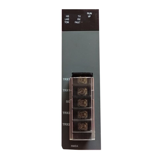
Chapter 2 Specifications 2.3 Structure and Characteristics 1) LED display - XGL-RMEA ◀ LED display ◀ Cable connection part SILK display LED Description Normal Normal Error Serious defect, Contact Customer Service Center Blinks Normal Normal On/Off Error Serious defect, Contact Customer Service Center Normal Normal Blinks... - Page 21 Chapter 2 Specifications XGL-RMEB ◀ LED display ◀ Cable connection part SILK display LED Description Normal Normal Error Serious defect, Contact Customer Service Center Blinks Normal Normal On/Off Error Serious defect, Contact Customer Service Center Normal Normal Blinks Standby Downloading parameters while High-speed Link enabled Fatal link failure occurs in high speed link service when high Error speed link is enabled...
- Page 22 Chapter 2 Specifications GOL-RR8T SILK display LED Description Normal DC 24V power is connected normally. Error DC 24V power is not connected. LINK IN port is working normally Blink Normal (Rnet master must be connected to LINK IN) LINK Error LINK IN port is malfunctioned or Rnet master signal has problem.
- Page 23 Chapter 2 Specifications 2) Cable connection part (1) Cable specifications - LS cables (Standard cable) LIREV-AMESB Designations Structure 2 * 0.64mm 22AWG Manufacturer LS Cables Conductor Cable type Shielded twisted pair Insulated 59Ω/km (normal temperature) Conductor resistance Voltage resistance (DC) 500 V/Min (normal temperature) Insulated resistance 1,000 MΩ/km or more...
-
Page 24: Terminating Resistor
Chapter 2 Specifications 2.4 Terminating resistor 1) How to install terminating resistor Be sure to install the terminating resistor on the both ends of the line. (Rnet I/F module and last slave node) Connect Rnet I/F module with TRX2+ and TRX2- and Smart I/O Rnet module with TRX2+ and TRX2-. ... - Page 25 Chapter 2 Specifications 2-10...
-
Page 26: Chapter 3 Installation And Test Operation Of The Product
Chapter 3 Installation and Test Operation of the Product Chapter 3 Installation and Test Operation of the Product 3.1 Precautions for Installation 3.1.1 Precautions for installation For system configuration through Rnet I/F module, carefully make sure of the following items prior to installation. - Page 27 Chapter 3 Installation and Test Operation of the Product...
-
Page 28: Chapter 4 System Configuration
Chapter 4 System Configuration Chapter 4 System Configuration 4.1 System Configuration of Network The communication system between Rnet I / F modules can be configured as follows In order to connect to LS inverter, Rnet I / F option module must be installed in LS inverter to enable communication. - Page 29 Chapter 4 System Configuration 4.1.3 Mixed configuration 2 between XGL-RMEA/B + repeater + Rnet slave...
-
Page 30: Chapter 5 High-Speed Link Setting
Chapter 5 High-speed Link Setting Chapter 5 High-speed Link Setting 5.1 Introduction High-speed link specifies the Send/Receive device area and data size between CPU module and the communication module by XG5000. High-speed link can be set the function as shown below. Description High-speed Link Module type... -
Page 31: How To Use Xg5000
Chapter 5 High-speed Link Setting 5.2 How to use XG5000 XG5000 usage for Rnet I/F module is as shown below. XG5000 execution 1) Project → New Project Creating New file for Rnet I/F module (1) Project name A) Writing the project name (2) PLC Series A) Selecting PLC series (3) CPU kind... - Page 32 Chapter 5 High-speed Link Setting 4) Write Parameter (Standard Settings, HS Link, P2P) Write of High-speed link parameter value of installed Rnet I/F module. 5) Enable Link (HS Link, P2P) Communication permission of installed Rnet I/F module.
- Page 33 Chapter 5 High-speed Link Setting * Enable Link through flag It describes “Enable Link” method through flag. The following XG5000 version, CPU OS version is needed. Item Version XG5000 V3.61 or above XGR CPU V1.91 or above XGI CPU V3.4 or above XGK CPU V3.7 or above Flag list related with “Enable Link”...
- Page 34 Chapter 5 High-speed Link Setting Flag Data type Device Description _HS9_REQ F10308 HS link 9 enable/disable request _HS10_REQ F10309 HS link 10 enable/disable request _HS11_REQ F1030A HS link 11 enable/disable request _HS12_REQ F1030B HS link 12 enable/disable request _HS1_REQ_NUM F10310 HS link 1 enable/disable setting _HS2_REQ_NUM F10311...
-
Page 35: High-Speed Link Editing
Chapter 5 High-speed Link Setting 5.3 High-speed Link Editing XG5000 is executed as shown below. [Standard window] The parameter in XG5000 is as shown below. Basic setting High-speed link [Parameter window] Rnet I/F module is set in High-speed link window. It can use the High-speed link up to maximum 12. - Page 36 Chapter 5 High-speed Link Setting 1) How to use High-speed link window Parameter is specified at High-speed link window as shown below. There are 2 kinds of parameter setting, Communication module setting and High-speed link block setting. High-speed link Parameter setting Communication module setting High-speed link block setting Remark...
- Page 37 Chapter 5 High-speed Link Setting 2) Communication module setting parameter Communication module parameter setting is as shown below. Parameter Setting item Description Module Rnet type Communication Setting range: 0 ~ 7 Base no. module Setting It is different from CPU module. Setting range: 0 ~ 11 Slot no It is different from type of base.
- Page 38 Chapter 5 High-speed Link Setting 3) Parameter of High-speed link block setting High-speed link block setting parameter is as shown below. Block window Select by mouse then module type setting screen is opened as shown below. Item Description 1.DC input 16points GRL-D22A/D22A(N) 2.DC input 32points GRL-D24A/D24A(N)
- Page 39 Chapter 5 High-speed Link Setting (3) How to use High-speed link block editing tool The editing tool and usage of High-speed link block is as shown below. Screen 1: click right mouse button of a selected area. Edit Block Changes the edited index block. Copy Block Copies the edited index block.
-
Page 40: Read And Write Of High-Speed Link
Chapter 5 High-speed Link Setting 5.4 Read and Write of High-speed Link The screen is used for read/write of High-speed link’s parameter. (Online menu → Read or Write) Configuration Description 1) High-speed link is available up to 12 for installed Rnet I/F module. -
Page 41: System Diagnosis
Chapter 5 High-speed Link Setting 5.5 System Diagnosis System diagnosis provides the information of Rnet I/F module system. The System diagnosis screen is as shown below. Menubar System diagnosis window It describes the menu of system diagnosis. 1) Communication module information Screen configuration and description Module kind Communication module type. - Page 42 Chapter 5 High-speed Link Setting 2) HS link Screen configuration and description Base no. Base number of communication module which is connected with High-speed link. Standard information Slot no. Slot number of communication module which is connected with High-speed link. 1: High-speed link parameters are communicate normally after power on.
- Page 43 Chapter 5 High-speed Link Setting 3) Auto-scan Menu Screen configuration and description Auto-scan Communication status of the slave module is displayed as shown below. 1) Connected communication : 2) Disconnected communication: But, it is not shown about GRL-TR4A which was produced before dated 2007 year during auto-scan.
- Page 44 Chapter 5 High-speed Link Setting 4) System Log Shows updated log information. Screen contents Base No. Base number of communication module Slot No. Slot number of communication module Link Type Display network type of connected communication module Select log area Select RunningLog or SystemLog 5-15...
- Page 45 Chapter 5 High-speed Link Setting 5) View Communication Module Log Indicates event and communication history occurred in communication module Screen contents Display all event history information related to communication Even History module History mode Main communication history information related to Comm log communication module Base No.
-
Page 46: High-Speed Link Information
Chapter 5 High-speed Link Setting 5.6 High-speed Link Information High-speed link swaps the data among master module and all slave modules. It provides the flag of High-speed link operation status classified by individual station or total station. It is useful when checking the reliability of Transmission/Reception data and finding cause of error. Flag kinds and usage is as shown below. - Page 47 Chapter 5 High-speed Link Setting Monitoring of flag and device’s value is as shown below. XG5000 Project window Global/Direct Variable Setting sequence XG5000 Monitor tap How to use - Select variable in Variable/Comment screen and then Drag/Drop the variable to Variable Monitoring Window.
-
Page 48: Chapter 6 Program Example
Chapter 6 Program Example Chapter 6 Program Example 6.1 XG5000 program The basic configuration and setting values of the example are as follows. Setting items Setting value Base No. Slot No. Station No. 0 (fixed) Comm Speed 1Mbps (fixed) High-Speed link setting High-Speed link 02 Comm period setting 200ms... - Page 49 Chapter 6 Program Example The high speed link parameter for the example system is set as follows. Used S/W Action Contents XG5000 XG5000 execute execute Project New project Create New project Set project name, CPU type XG5000 XG5000 Online Connection setting Select connection driver Connection setting XG5000...
- Page 50 Chapter 6 Program Example Select modules Set High-speed link block High speed link block after setting read area / save area Write High- Online Write : Check high speed links and write speed link blocks Online Set communication module Link enable : Enable High- Enable High- speed link speed link...
- Page 51 Chapter 6 Program Example...
-
Page 52: Appendix
Appendix Appendix A.1 Terminology 1) Master Module Rnet I/F module to be installed on I/O location of the basic base. 2) Slave Module (RSM : Rnet Slave Module) Rnet I/F module to be installed on CPU location of the basic base or Smart I/O Rnet. 3) Local Station Station directly connected with XG5000, XG5000 in the same network including CPU for user to download, monitoring and debug programs. -
Page 53: List Of Hs Link Flags
Appendix A.2 List of HS Link Flags Keyword Type Detail Description Displays all stations normally operated as specified in HS link parameter, which will be On if 1. There is no error with all stations specified in parameter HS link parameter in RUN mode No.1’s all stations 2. - Page 54 Appendix Notes HS link No. L area address Remarks Compared with HS link of 1 in [Table 1], other HS link station number’s L000500~L00099F L001000~L00149F flag address will be simply calculated as follows; L001500~L00199F L002000~L00249F Calculation formula: L002500~L00299F L area address = L000000 + 500 x (HS link No. – 1) L003000~L00349F L003500~L00399F In order to use HS link flag for program and monitoring, use the flag map...
-
Page 55: External Dimensions
Appendix A.3 External Dimensions 1) XGL-RMEA/B Unit: mm 2) GOL-RR8T Unit: mm... - Page 56 3. Since the above warranty is limited to PLC unit only, make sure to use the product considering the safety for system configuration or applications. Environmental Policy LS ELECTRIC Co., Ltd supports and observes the environmental policy as below. Environmental Management About Disposal LS ELECTRIC’...
- Page 57 Warranty and Environment Policy...
- Page 58 ■ Headquarter ■ Overseas Subsidiaries • LS ELECTRIC Japan Co., Ltd. (Tokyo, Japan) LS-ro 127(Hogye-dong) Dongan-gu, Anyang-si, Gyeonggi-Do, 14119, Korea Tel: 81-3-6268-8241 E-Mail: jschuna@lselectric.biz • LS ELECTRIC (Dalian) Co., Ltd. (Dalian, China) ■ Seoul Office Tel: 86-411-8730-6495 E-Mail: jiheo@lselectric.com.cn •...
Need help?
Do you have a question about the XGT Series and is the answer not in the manual?
Questions and answers