Sign In
Upload
Manuals
Brands
L-Card Manuals
Media Converter
ADC Series
L-Card ADC Series Manuals
Manuals and User Guides for L-Card ADC Series. We have
1
L-Card ADC Series manual available for free PDF download: User Manual
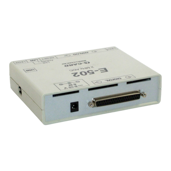
L-Card ADC Series User Manual (69 pages)
Measuring voltage converters
Brand:
L-Card
| Category:
Media Converter
| Size: 1 MB
Table of Contents
Table of Contents
4
Chapter 1. General Description
7
Order Information
8
Fig. 1-1. the Notation System of the E-502 Module
8
Distribution Kit
9
Appearance and Main Structural Elements
10
Fig.1-2. Front View (Front Panel)
10
Fig.1-3. Back View (Back Panel)
10
Chapter 2. Installation and Configuration
11
E-502 Configuration "By Default
11
Internal Construction Elements and E-502 Configuration
12
Fig. 2-1. Internal Configuration
12
Configuration of the DAC Outputs of the Connector Analog (DAC1/+15V/AGND/NC and DAC2/-15V/DGND/NC)
13
Configuration of the Resolution of the Active State of the Digital Outputs DO1
13
On the Digital Connector
13
Functions of the Status Leds on the Front Panel
13
Led1
13
Led2
14
LEDS Link and Activity (on LAN Connector) in Modifications E-502-P-EU
14
RESET Functions
14
Serial Number. E-502 Version Number. Module Identification in a Multi-Module Configuration
15
E-502 Application as a Part of User Programs
15
Software Installation
15
Ethernet Interface Configuration
15
Chapter 3. The Mechanism and Principle of Operation of E-502
16
Conventions
16
Convention on Numbering
16
The Assumption on the Concept of "Frequency
16
Introduction (General Information)
16
Operation Principle
17
Reference Frequency
18
ADC Channel
18
Digital Input Channel
19
Digital Output and DAC Channels
19
Fig. 3-1. Illustration of the Personnel Principle for Acquiring ADC Data
19
E-502 Synchronization General Principle
20
Fig. 3-2. Synchronization System Structure in E-502
21
Adjustment of the Ratio between the Time of Setting the Signal and the Resolution for each ADC Channel
22
Relative Switching Delays in ADC Channels
23
Fig. 3-3. the Principle of Obtaining ADC Data (in Detail)
23
Relative Delays of the ADC, DAC and I/O Channels
25
Fig.3-4. Synchronous I/O Diagram
25
Operation Principle and Function Circuit
27
Fig. 3-5. Block Diagram
27
All Functional Differences of E-502 and L-502
29
Chapter 4. Connection of Signals
30
DGND, AGND Circuits
30
GND, 0 V, GND_USB, CHASSIS Circuits
30
Fig. 4-1: Internal Connection of the "Common Wires" Circuits in E-502
30
E-502 Connectors Description
31
Connector Analog
31
Fig. 4-2: the Location of the "Common Wires" Circuits on the E-502 Board
31
Table 4-1: Connector Analog
32
Fig. 4-3: Connector Analog
32
Connector Digital
34
Fig. 4-4: Connector Digital
34
Table 4-2: Connector Digital
35
Fig. 4-5: Synchronization Scheme Master - Slave
37
Fig. 4-6: Synchronization Scheme Master - Two Slaves
37
Fig. 4-7: Example of a Two-Circuit Synchronization Scheme
38
Fig. 4-8: Example of a Grouped Connection of Digital Lines: Three Buses of 8 Bits each
38
JTAG Connectors of Blackfin Processor
39
Connectors JTAG and UART0 of the ARM Controller LPC-4333 (LPC-4337)
39
Fig. 4-9. Detailing of Signals on JTAG Blackfin JTAG ARM and UART0 Connectors
39
The Maximum Allowable Conditions at the Inputs and Outputs of Signal Lines
40
Table 4-3 Maximum Permissible E-502 Input/Output Conditions
40
Table 4-4 Maximum Permissible through Currents by Common Wires Circuits
40
ADC Input Operation Voltage Range
41
Preconditions for Correct Connection and Correct Settings of the Input of the ADC E-502
43
The Physical Causes of Possible Problems
43
Conditions for Correct E-502 Connection and Settings
43
Calculation of Total Load Power of E-502 Output Circuits
44
Chapter 5. Specifications
46
Adc
46
Limits of the Permissible Relative Basic Error of Measuring the AC Voltage
47
ADC Own Input Noise
47
ADC Inter-Channel Passing
48
Dac
48
AC Voltage Playback Error
48
Digital Inputs
49
Digital Outputs
50
Synchronization in E-502
50
Characteristics of Standard Interfaces
51
Power Supply System and Galvanic Isolation
52
Construction Specification
53
Environmental Conditions
53
Normal Conditions
53
Operating Conditions
53
Chapter 6. Connexion Samples
54
ADC Entry Point Connection
54
Connecting to the ADC Entry Point of Single-Phase Voltage Source
54
Connection to ADC Input with up to 16 Differential Voltage Sources
57
Connection to the ADC Input for the Case Where the Common Wire of the Signal
58
Sources Has a Offset Potential Ucm of Max. ± 1 V Relative to the AGND Circuit
58
Measurement of the Voltage Drop on the Circuit Section in the Differential Mode (up to 16- Channels)
58
Differential Connection of the Transformer (Throttle) Winding with Midpoint and Offset Potential with Respect to AGND
59
Example of Mixed Connection of Voltage Sources "With Common Ground" and Differential
59
Connecting a Power Supply to the ADC Input
59
The Coordinated Connection of Remote Sources of Current or Voltage through a Long Line with a Wave Impedance Zw
61
The Coordinated Connection of a Remote Voltage Source through a Pair of Long Line with a Wave Resistance Zw with Matching on the Signal Source Side
62
Connecting the DAC Outputs
63
Mode "With Common Ground" 2-Channel Output ±5 V
63
Single-Channel Differential Output ±10 V
63
Connecting the Digital Inputs and Outputs
64
Connecting the LED or the Optron Input. Option 1
64
Connecting the LED or the Optron Input. Option 2
64
Connecting a Contact to a Digital Input
64
Connect the Optron Output to the Synchronization Input
64
Chapter 7. Design Data
65
Circuit Plate Draft
65
Front Panel Draft
66
Back Panel Draft
66
List of Figures
68
Advertisement
Advertisement
Related Products
L-Card DAC Series
L-Card E-502-P-EU-D
L-Card E-502-P-EU-D-I
L-Card E-502-X-EU-X
L-Card E-502-X-U-D
L-Card E-502-X-U-X
L-Card E20-10
L-Card E20-10-1
L-Card E20-10-D
L-Card E20-10-D-1
L-Card Categories
Media Converter
More L-Card Manuals
Login
Sign In
OR
Sign in with Facebook
Sign in with Google
Upload manual
Upload from disk
Upload from URL