Keysight Technologies N9030B Manuals
Manuals and User Guides for Keysight Technologies N9030B. We have 12 Keysight Technologies N9030B manuals available for free PDF download: Service Manual, Getting Started And Troubleshooting Manual, Security Features And Document Of Volatility, Installation Note, Installation Notes

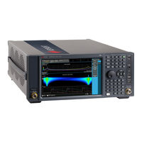
Keysight Technologies N9030B Service Manual (617 pages)
PXA Signal Analyzer
Brand: Keysight Technologies
|
Category: Measuring Instruments
|
Size: 37 MB
Table of Contents
Advertisement

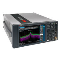
Keysight Technologies N9030B Getting Started And Troubleshooting Manual (93 pages)
Signal Analyzer
Brand: Keysight Technologies
|
Category: Measuring Instruments
|
Size: 4 MB
Table of Contents
Keysight Technologies N9030B Security Features And Document Of Volatility (58 pages)
Brand: Keysight Technologies
|
Category: Measuring Instruments
|
Size: 0 MB
Table of Contents
Advertisement

Keysight Technologies N9030B Installation Note (33 pages)
Signal Analyzer, Option BBA Analog Baseband IQ Inputs Upgrade Kit
Brand: Keysight Technologies
|
Category: Measuring Instruments
|
Size: 2 MB
Table of Contents

Keysight Technologies N9030B Installation Note (21 pages)
PXA Signal Analyzer, Option HL1 Microwave Preselector Bypass (MPB) and Low Noise Path (LNP)
Brand: Keysight Technologies
|
Category: Measuring Instruments
|
Size: 2 MB
Table of Contents

Keysight Technologies N9030B Installation Note (20 pages)
PXA Signal Analyzer
Brand: Keysight Technologies
|
Category: Measuring Instruments
|
Size: 3 MB
Table of Contents
Keysight Technologies N9030B Installation Notes (19 pages)
PXA Signal Analyzer
Brand: Keysight Technologies
|
Category: Measuring Instruments
|
Size: 0 MB
Table of Contents

Keysight Technologies N9030B Installation Note (17 pages)
PXA Signal Analyzer
Brand: Keysight Technologies
|
Category: Measuring Instruments
|
Size: 1 MB
Table of Contents

Keysight Technologies N9030B Installation Note (13 pages)
PXA Signal Analyzer
Brand: Keysight Technologies
|
Category: Measuring Instruments
|
Size: 1 MB

Keysight Technologies N9030B Installation Note (9 pages)
PXA Spectrum Analyzer, Option C35, 3.5 mm Input Connector Retrofit Kit
Brand: Keysight Technologies
|
Category: Measuring Instruments
|
Size: 0 MB
Table of Contents

Keysight Technologies N9030B Installation Note (10 pages)
PXA Signal Analyzer, Option CR3 Second IF Out/CRP Arbitrary IF Out/ALV Log Video Out
Brand: Keysight Technologies
|
Category: Measuring Instruments
|
Size: 0 MB

Keysight Technologies N9030B Installation Note (9 pages)
CXA and PXA Signal Analyzer
Brand: Keysight Technologies
|
Category: Measuring Instruments
|
Size: 0 MB
Advertisement
Related Products
- Keysight Technologies N9030A
- Keysight Technologies N9030AK-MTU
- Keysight Technologies N9030AK-MTP
- Keysight Technologies N9032B PXA
- Keysight Technologies N9038B
- Keysight Technologies N9000A
- Keysight Technologies N9020A
- Keysight Technologies N9010A Option 532
- Keysight Technologies N9010A Option 507
- Keysight Technologies N9000-90032