Sign In
Upload
Manuals
Brands
IEI Technology Manuals
Computer Hardware
PCIE-Q470
IEI Technology PCIE-Q470 Manuals
Manuals and User Guides for IEI Technology PCIE-Q470. We have
2
IEI Technology PCIE-Q470 manuals available for free PDF download: User Manual, Quick Installation Manual
IEI Technology PCIE-Q470 User Manual (90 pages)
Brand:
IEI Technology
| Category:
PCI Card
| Size: 6.8 MB
Table of Contents
Table of Contents
5
Introduction
12
Ntroduction
13
Figure 1-1: PCIE-Q470
13
Features
14
Connectors
15
Figure 1-2: Connectors
15
Dimensions
16
Figure 1-3: PCIE-Q470 Dimensions (MM)
16
Data Flow
17
Figure 1-4: Data Flow Diagram
17
Technical Specifications
18
Table 1-1: PCIE-Q470 Specifications
20
Packing List
21
Anti-Static Precautions
22
Unpacking Precautions
22
Packing List
23
Table 2-1: Packing List
23
Optional Items
24
Table 2-2: Optional Items
24
Connectors
25
Peripheral Interface Connectors
26
PCIE-Q470 Layout
26
Figure 3-1: Peripheral Interface Connectors
26
Peripheral Interface Connectors
27
External Interface Panel Connectors
28
Table 3-1: Peripheral Interface Connectors
28
Table 3-2: External Peripheral Connectors
28
Internal Peripheral Connectors
29
CPU 12V Power Connector
29
Figure 3-2: ATX CPU 12V Power Connector Location
29
Table 3-3: ATX CPU 12V Power Connector Pinouts
29
Battery Connector
30
Figure 3-3: Battery Connector Location
30
Chassis Intrusion Connector
31
Figure 3-4: Chassis Intrusion Connector Location
31
Table 3-4: Chassis Intrusion Connector Pinouts
31
Digital Input/Output Connector
32
Figure 3-5: Digital I/O Connector Location
32
Table 3-5: Digital I/O Connector Pinouts
32
EC Debug Connector
33
Figure 3-6: EC Debug Connector Location
33
Table 3-6: EC Debug Connector Pinouts
33
Fan Connectors (CPU)
34
Figure 3-7: CPU Fan Connector Location
34
Table 3-7: CPU Fan Connector Pinouts
34
Fan Connectors (System)
35
Figure 3-8: System Fan Connector Location
35
Table 3-8: System Fan (SYS_FAN1) Connector Pinouts
35
Audio Connector
36
Figure 3-9: Audio Connector Location
36
Table 3-9: Audio Connector Pinouts
36
Front Panel Connector
37
Figure 3-10: Front Panel Connector Location
37
Table 3-10: Front Panel Connector Pinouts
37
I 2 C Connector
38
Figure 3-11: I 2 C Connector Location
38
Table 3-11: I 2 C Connector Pinouts
38
Smbus Connector
39
Figure 3-12: Smbus Connector Location
39
Table 3-12: Smbus Connector Pinouts
39
LAN Link LED Connector
40
Figure 3-13: LAN LED Connector Locations
40
Table 3-13: LAN LED Connector Pinouts
40
A-Key Slot
41
Figure 3-14: M.2 A-Key (2230) Slot Location
41
Table 3-14: M.2 A-Key (2230) Slot Pinouts
42
B-Key Slot
43
Figure 3-15: M.2 B-Key (3042/3052/2242/2280) Slot Location
43
Table 3-15: M.2 B-Key (3042/3052/2242/2280) Slot Pinouts
44
M-Key Slot (on Solder Side)
45
Figure 3-16: M.2 M-Key (2242/2280) Slot Location
45
Table 3-16: M.2 M-Key (2242/2280) Slot Pinouts
46
On-Board Power Switch
47
DDR4 DIMM Slots
47
Figure 3-17: Power Button Location
47
SATA 6Gb/S Connectors
48
Figure 3-18: DDR4 DIMM Socket Locations
48
RS-232 Serial Port Connectors
49
Figure 3-19: SATA 6Gb/S Connector Locations
49
Table 3-17: SATA 6Gb/S Connector Pinouts
49
RS-422/485 Serial Port Connectors
50
Figure 3-20: RS-232 Serial Port Connector Location
50
Table 3-18: RS-232 Serial Port Connector Pinouts
50
Figure 3-21: RS-422/485 Serial Port Connectors Location
51
Table 3-19: RS-422/485 Serial Port Connectors Pinouts
51
Table 3-20: DB-9 RS-422/485 Pinouts
51
Flash SPI ROM Connector
52
Figure 3-22: Flash SPI ROM Connector Location
52
Table 3-21: Flash SPI ROM Connector Pinouts
52
Flash EC ROM Connector
53
Figure 3-23: Flash EC ROM Connector Location
53
Table 3-22: Flash EC ROM Connector Pinouts
53
SIM Card Slot
54
Figure 3-24: SIM Card Slot Connector Location
54
Table 3-23: SIM Card Slot Connector Pinouts
54
Internal USB 2.0 Connectors
55
Figure 3-25: Internal USB 2.0 Connector Locations
55
Table 3-24: Internal USB 2.0 Connector Pinouts
55
Internal USB 3.2 Gen 1 Connector (Type-A)
56
Figure 3-26: Internal USB 3.2 Gen 1 Connector Location
56
Table 3-25: Internal USB 3.2 Gen 1 Connector Pinouts
56
Internal USB 3.2 Gen 1 Connector
57
Figure 3-27: Internal USB 3.2 Gen 1 Connector Location
57
Table 3-26: Internal USB 3.2 Gen 1 Connector Pinouts
57
External Peripheral Interface Connector Panel
58
Figure 3-28: External Peripheral Interface Connector
58
External 2.5Gbe RJ-45 Connectors
59
Figure 3-29: LAN Location
59
Figure 3-30: LAN LED Location
59
Table 3-27: LAN Pinouts
59
Table 3-28: LAN LED Pinouts
59
External HDMI Connector
60
Figure 3-31: HDMI Connector
60
Table 3-29: HDMI Connector Pinouts
60
External USB 3.2 Gen 1 Connectors (Type-A)
61
Figure 3-32: USB 3.2 Gen 1 Connectors (Type-A)
61
Table 3-30: External USB 3.2 Gen 1 Connectors (Type-A) Pinouts
61
External USB 3.2 Gen 2 Connector (Type-C)
62
Figure 3-33: USB 3.2 Gen 2 Type-C Port Location
62
Table 3-31: USB 3.2 Gen 2 Type-C Port Pinouts
62
Installation
63
Anti-Static Precautions
64
Installation Considerations
64
Socket Lga1200 Cpu Installation
66
Figure 4-1: Disengage the CPU Socket Load Lever
66
Figure 4-2: Remove Protective Cover
67
Figure 4-3: Insert the Socket LGA1200 CPU
68
Figure 4-4: Close the Socket LGA1200
68
Socket Lga1200 Cooling Kit Installation
69
Figure 4-5: Cooling Kit Support Bracket
70
DIMM Installation
71
Figure 4-6: DIMM Installation
71
System Configuration
72
AT/ATX Power Mode Setting
72
Figure 4-7: AT/ATX Power Mode Switch Location
72
Table 4-1: AT/ATX Power Mode Switch Settings
72
BIOS Selection Switch
73
Figure 4-8: BIOS Switch Locations
73
Table 4-2: BIOS Switch Settings
73
Clear CMOS Button
74
Pcie X16 Channel Mode Setup
74
Figure 4-9: Clear CMOS Button Location
74
Table 4-3: Pcie X16 Channel Mode Setup
74
Flash Descriptor Security Override Jumper
75
Figure 4-10: Flash Descriptor Security Override Jumper Location
75
Table 4-4: Flash Descriptor Security Override Jumper Settings
75
USB Power Selection
76
Table 4-5: BIOS Options and Configured USB Ports
76
Table 4-6: USB Power Source Setup
76
Internal Peripheral Device Connections
77
SATA Drive Connection
77
Figure 4-11: SATA Drive Cable Connection
77
Figure 4-12: SATA Power Drive Connection
78
Software Installation
79
Driver Download
79
Figure 4-13: IEI Resource Download Center
79
Intel ® Amt Setup Procedure
81
A Regulatory Compliance
82
B Product Disposal
84
C Error Beep Code
86
Pei Beep Codes
87
Dxe Beep Codes
87
D Hazardous Materials Disclosure
88
Rohs II Directive (2015/863/EU)
89
China Rohs
90
Advertisement
IEI Technology PCIE-Q470 Quick Installation Manual (19 pages)
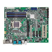
Full-size PICMG 1.3 CPU Card Supports 10th/11th Gen. LGA1200 Intel Core i9/i7/i5/i3, Pentium and Celeron Processors, Intel Q470, DDR4, HDMI, Dual Intel 2.5GbE, USB 3.2, SATA 6Gb/s, M.2, iAudio and RoHS
Brand:
IEI Technology
| Category:
Computer Hardware
| Size: 0.71 MB
Advertisement
Related Products
IEI Technology PCIE-9152
IEI Technology PCIE-Q350
IEI Technology PCIE-H610
IEI Technology PCIE-9452
IEI Technology PCIE-Q370-R11
IEI Technology PCIE-Q170-R10
IEI Technology PCIE-9650
IEI Technology PCISA-PV-D5251T
IEI Technology PCISA-LX
IEI Technology PCISA-BT-E38451
IEI Technology Categories
Motherboard
Touch Panel
Computer Hardware
Single board computers
Desktop
More IEI Technology Manuals
Login
Sign In
OR
Sign in with Facebook
Sign in with Google
Upload manual
Upload from disk
Upload from URL