Sign In
Upload
Manuals
Brands
IEI Technology Manuals
Computer Hardware
PCISA-LX
User Manuals: IEI Technology PCISA-LX PCISA CPU Card
Manuals and User Guides for IEI Technology PCISA-LX PCISA CPU Card. We have
1
IEI Technology PCISA-LX PCISA CPU Card manual available for free PDF download: User Manual
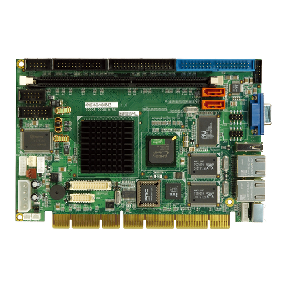
IEI Technology PCISA-LX User Manual (214 pages)
PCISA CPU CARD with AMD LX 800-500MHz processoe Audio, CRT, TTL LCD, and Dual LAN
Brand:
IEI Technology
| Category:
Computer Hardware
| Size: 6 MB
Table of Contents
Table of Contents
3
Introduction
15
Pcisa-Lx Cpu Card Overview
16
PCISA-LX Features
16
PCISA-LX Applications
16
PCISA-LX Benefits
16
Figure 1-2: PCISA-LX Solder Side Overview
17
Pcisa-Lx Overview
17
Figure 1-1: PCISA-LX Overview
17
PCISA-LX Connectors
18
Technical Specifications
19
Table 1-1: Technical Specifications
20
Detailed Specifications
21
Compatible Iei Backplanes
22
Board Dimensions
22
Cpu Support
22
Overview
22
System Chipset
23
Data Flow
25
Figure 2-1: Data Flow Block Diagram
25
Graphics Support
26
Table 2-1: Geode LX Graphics Processor Features
27
Pci Bus Interface Support
27
Memory Support
27
Super I/O
28
Ethernet
31
Drive Interfaces
32
SATA Drives
32
IDE HDD Interfaces
32
Floppy Disk Drive (FDD)
32
Serial Ports
32
Audio Codec
33
System Monitoring
34
Real Time Clock
34
Bios
35
Operating Temperature and Temperature Control
35
Power Consumption
35
Table 2-2: Power Consumption
35
Packaged Contents and Optional Accessory Items
36
Package Contents
36
Optional Accessory Items
36
Connectors and Jumpers
37
Figure 3-1: Connector and Jumper Locations
38
Peripheral Interface Connectors
38
PCISA-LX Layout
38
Peripheral Interface Connectors
39
External Peripheral Interface Connectors
40
Table 3-1: Peripheral Interface Connectors
40
Table 3-2: External Peripheral Interface Connectors
40
On-Board Jumpers
41
Internal Peripheral Connectors
41
AT Power Connector
41
Table 3-3: On-Board Jumpers
41
Table 3-4: at Power Connector Pinouts
42
ATX Power Button Connector
42
Figure 3-2: at Power Connector Location
42
Audio Connector (10-Pin)
43
Figure 3-3: ATX Power Button Connector Location
43
Table 3-5: ATX Power Button Connector Pinouts
43
Battery Connector
44
Figure 3-4: Audio Connector Location
44
Table 3-6: Audio Connector Pinouts
44
Table 3-7: Battery Connector Pinouts
45
Figure 3-5: Battery Connector Location
45
Compact Flash ® Connector
45
Figure 3-6: Compact Flash ® Connector Location
46
Table 3-8: Compact Flash ® Connector Pinouts
47
Fan Connector (+5V)
48
Figure 3-7: +12V Fan Connector Location
48
Table 3-9: +12V Fan Connector Pinouts
48
Floppy Disk Connector
49
Figure 3-8: 34-Pin FDD Connector Location
49
Table 3-10: 34-Pin FDD Connector Pinouts
50
GPIO Connector
50
IDE Connector
51
Figure 3-9: GPIO Connector Location
51
Table 3-11: GPIO Connector Pinouts
51
Figure 3-10: IDE Device Connector Location
52
Keyboard/Mouse Connector
53
Table 3-12: Primary IDE Connector Pinouts
53
LCD Inverter Power Connector
54
Figure 3-11: Keyboard/Mouse Connector Location
54
Table 3-13: Keyboard/Mouse Connector Pinouts
54
Table 3-14: Inverter Connector Pinouts
55
Figure 3-12: LCD Inverter Connector Location
55
LED Connector
55
Table 3-15: LED Connector Pinouts
56
Parallel Port Connector
56
Figure 3-13: LED Connector Location
56
Figure 3-14: Parallel Port Connector Location
57
Table 3-16: Parallel Port Connector Pinouts
57
Reset Button Connector
58
Figure 3-15: Reset Button Connector Location
58
Table 3-17: Reset Button Connector Pinouts
58
Serial Port (COM1) Connector
59
Figure 3-16: RS-232 Serial Port Connector Location
59
RS-232/422/485 COM Serial Port (COM2, COM3) Connector
60
Table 3-18: RS-232 Serial Port Connector Pinouts
60
SATA Drive Connectors
61
Figure 3-17: RS-232/422/485 Serial Port Connector Location
61
Table 3-19: RS-232/422/485 Serial Port Connector Pinouts
61
Suspend Power and PSON# Signal Connector
62
Figure 3-18: SATA Drive Connector Locations
62
Table 3-20: SATA Drive Connector Pinouts
62
Figure 3-19: Suspend Power and PSON# Signal Connector Location
63
Table 3-21: Suspend Power and PSON# Signal Connector Pinouts
63
Figure 3-20: TFT LCD LVDS Connector Location
64
TFT LCD LVDS Output Connector
64
TFT LCD TTL Output Connector
65
Table 3-22: TFT LCD LVDS Connector Pinouts
65
Figure 3-21: TFT LCD TTL Connector Location
66
USB Connectors
67
Table 3-23: TFT LCD TTL Connector Pinouts
67
External Peripheral Interface Connector Panel
68
Figure 3-22: USB Connector Location
68
Table 3-24: CN6 USB Port Connector Pinouts
68
Table 3-25: CN8 USB Port Connector Pinouts
68
Figure 3-23: PCISA-LX External Peripheral Interface Connector Panel
69
LAN Connectors
70
Table 3-26: LAN Pinouts
70
Mini-DIN 6 PS/2 Connector
71
Figure 3-24: RJ-45 Ethernet Connector
71
Table 3-27: RJ-45 Ethernet Connector Leds
71
USB Connector
72
Figure 3-25: Mini-DIN 6 PS/2 Connector
72
Table 3-28: Mini-DIN 6 PS/2 Connector
72
Table 3-29: USB Port Pinouts
73
Figure 3-26: VGA Connector
73
VGA Connector
73
Table 3-30: VGA Connector Pinouts
74
Installation
75
Anti-Static Precautions
76
Installation Considerations
76
Installation Notices
76
Unpacking
77
Unpacking Precautions
77
Checklist
78
Pcisa-Lx Cpu Card Installation
78
Purchasing the Memory Module
79
DIMM Module
79
Preinstalled Component
79
Components to Install
79
DIMM Module Installation
80
Figure 4-1: Installing the DIMM Module
80
Peripheral Device Connection
81
IDE Disk Drive Connector
81
Table 4-1: IEI Provided Cables
81
COM2-COM3 RS-232 Serial Port Installation
82
Figure 4-2: Connection of IDE Connector
82
TFT TTL LCD Installation
83
LCD Backlight Installation
83
TFT LVDS LCD Installation
83
Power Connection
83
Jumper Settings
84
AT Power Select Jumper
85
Figure 4-3: Jumper Locations
85
COM2 RS-422/485 Select Jumper
86
LCD Clock Jumper
86
Table 4-2: at Power Select Jumper Settings
86
Table 4-3: COM2 RS-/422/485 Select Settings
86
Table 4-5: LCD Voltage Setup Jumper Settings
87
LCD Voltage Select Jumper
87
Table 4-4: LCD Clock Jumper Settings
87
PCI VIO Voltage Select Jumper
88
Installing a Compact Flash ® Card
88
Table 4-6: PCI VIO Voltage Jumper Settings
88
Inserting the Cpu Card
89
Figure 4-4: Compactflash ® Card Installation
89
VGA Port Installation
90
USB Connection
90
Keyboard and Mouse Connection
90
Ethernet Connection
90
Rear Panel Connectors
90
Bios Settings
91
Starting Setup
92
Using Setup
92
Introduction
92
Getting Help
93
Unable to Reboot after Configuration Changes
93
Main BIOS Menu
93
Table 5-1: BIOS Navigation Keys
93
Save & Exit Setup
95
Exit Without Saving
95
Load Optimized Defaults
95
Set User Password
95
Set Supervisor Password
95
Load Fail-Safe Defaults
95
Standard Cmos Features
96
Date [Day MM:DD:yyyy]
96
Time [Hh/MM/Ss]
96
IDE Master and IDE Slave
96
Halt on [All, but Keyboard]
97
Drive a [1.44M, 3.5In]
97
Drive B [None]
97
IDE Primary Master/Slave
98
Base Memory
98
Extended Memory
98
Total Memory
98
IDE HDD Auto-Detection [Press Enter]
99
IDE Primary Master [Auto]
99
Cylinder
100
Capacity
100
Access Mode [Auto]
100
Advanced Bios Features
101
Head
101
Precomp
101
Landing Zone
101
Sector
101
Virus Warning [Disabled]
102
CPU Internal Cache [Enabled]
103
Quick Power on Self Test [Enabled]
103
Boot from LAN Control [Disabled]
103
SATA Boot ROM Control [Disabled]
104
Boot Device
104
Boot up Floppy Seek [Disabled]
105
Boot Other Device [Enabled]
105
Swap Floppy Drive [Disabled]
105
Boot up Numlock Status [On]
106
Gate A20 Option [Fast]
106
Typematic Rate Setting [Disabled]
106
Typematic Rate (Chars/Sec) [6]
106
Typematic Delay (Msec) [250]
107
Security Option [Setup]
107
OS Select for DRAM > 64MB [Non-OS2]
108
Security Option [Setup]
108
Small Logo (EPA) Show [Disabled]
109
Advanced Chipset Features
110
CPU Frequency [500Mhz]
110
Memory Frequency [Auto]
110
CAS Latency [Auto]
111
Interleave Select [LOI]
111
Video Memory Size [8M]
111
Onboard USB1.1 [Enabled]
112
Onboard USB2.0 [Enabled]
112
Flat Panel Configuration [Press Enter]
112
Onboard Audio [Enabled]
112
Output Display [Panel & CRT]
112
Flat Panel Configuration
113
Flat Panel Type [Auto]
113
Resolution [800 X 600]
114
Data Bus Type [9 - 24 Bits, 1 Ppc]
114
Refresh Rate [60Hz]
114
LP Active Period [Free Running]
115
SHFCLK Active Period [Free Running]
115
VSYNC Polarity Active [Low]
115
HSYNC Polarity [Low]
115
Integrated Peripherals
116
On-Chip IDE Channel 1 [Enabled]
116
Drive PIO Mode [Auto]
116
IDE UDMA [Auto]
117
IDE DMA Transfer Access [Enabled]
117
IT8888 ISA Decode IO [Press Enter]
117
Onboard Serial Port 1 [3F8/IRQ4]
118
Onboard FDC Controller [Enabled]
118
IDE HDD Block Mode [Enabled]
118
IT8888 ISA Decode Memory [Press Enter]
118
Onboard Serial Port 2 [2F8/IRQ3]
119
Onboard Serial Port 3 [Disabled]
119
Onboard Parallel Port [378/IRQ7]
119
Parallel Port Mode [SPP]
120
EPP Mode Select [EPP1.7]
120
ECP Mode Use DMA [3]
121
IT8888 ISA Decode IO
122
Decode IO Address N 0:15 [XX]
123
Decode IO Speed N [Fast Speed]
123
Decode IO Space N [Enabled]
123
IT8888 ISA Decode Memory
124
Decode IO Size N [Fast Speed]
124
Decode Memory Space N [Enabled]
125
Decode Memory Speed N [Fast Speed]
125
Decode Memory Address N [XX]
125
Power Management Setup
126
Decode Memory Size N [XX]
126
Standby Mode [Disabled]
127
Power Management [APM]
127
ACPI Suspend Type [S1 (POS)]
127
ACPI Function [Disabled]
127
Suspend Mode [Disabled]
128
Soft-Off by PWR-BTTN [Instant-Off]
129
Power-On by Alarm [Disabled]
129
Pnp/Pci Configurations
130
PNP os Installed [No]
130
Reset Configuration Data [Disabled]
130
Resources Controlled by [Auto (ESCD)]
131
IRQ Resources [Press Enter]
131
Memory Resources [Press Enter]
133
Reserved Memory Base [N/A]
133
Pc Health Status
134
Reserved Memory Length [8K]
134
PCI/VGA Palette Snoop [Disabled]
134
Fan Speed
135
Voltages
135
Driver Installation
137
Available Software Drivers
138
Isa Driver
138
Figure 6-1: AMD LX/GX CD Main Menu
139
Figure 6-2: AMD LX/GX CD Driver Menu
140
Vga Driver
141
Figure 6-3: Access Windows Control Panel
141
Figure 6-4: Double Click the System Icon
142
Figure 6-5: Double Click the Device Manager Tab
143
Figure 6-6: Device Manager List
144
Figure 6-7: Expand the Display Adapters Category
145
Figure 6-8: Update Driver
146
Figure 6-9: Upgrade Device Driver Wizard
147
Figure 6-10: Search for Suitable Driver
148
Figure 6-11: Locate Driver Files
149
Figure 6-12: Location Browsing Window
150
Audio Driver Installation
151
Figure 6-13: Access Windows Control Panel
151
Figure 6-14: Double Click the System Icon
152
Figure 6-15: Double Click the Device Manager Tab
153
Figure 6-16: Device Manager List
154
Figure 6-17: Search for Suitable Driver
155
Figure 6-18: Locate Driver Files
156
Lan Driver
157
Figure 6-19: Location Browsing Window
157
Figure 6-20: Locate the Setup Program Icon
158
Figure 6-21: Preparing Setup Screen
158
Figure 6-22: Install Wizard Welcome Screen
159
Figure 6-23: Installing Screen
160
Sata/Raid Driver
161
Figure 6-24: Restart the Computer
161
Figure 6-25: Locate the Setup Program Icon
162
Figure 6-26: Preparing Setup Screen
163
Figure 6-27: Install Wizard Welcome Screen
163
Figure 6-28: Installing Screen
164
Figure 6-29: RAID Driver Digital Signal
165
Figure 6-30: Installshield Wizard Complete Screen
166
Isa Driver
167
Figure 6-31: Access Windows Control Panel
167
Figure 6-32: Double Click the System Icon
168
Figure 6-33: Double Click the Device Manager Tab
169
Figure 6-34: Device Manager List
170
Figure 6-35: Search for Suitable Driver
171
Figure 6-36: Locate Driver Files
172
Figure 6-37: Location Browsing Window
173
A.1 BIOS Configuration Options
176
Index
211
Advertisement
Advertisement
Related Products
IEI Technology PCISA-PV-D5251T
IEI Technology PCISA-PV-N4551
IEI Technology PCISA-PV-N4551T
IEI Technology PCISA-MARK
IEI Technology PCISA-945GSE
IEI Technology PCISA-6612
IEI Technology PCISA-BT-E38451
IEI Technology PCISA-PV-N4551-R10
IEI Technology PCISA-PV-D4251
IEI Technology PCISA-PV-D4251T
IEI Technology Categories
Motherboard
Touch Panel
Computer Hardware
Single board computers
Desktop
More IEI Technology Manuals
Login
Sign In
OR
Sign in with Facebook
Sign in with Google
Upload manual
Upload from disk
Upload from URL