Sign In
Upload
Manuals
Brands
IEI Technology Manuals
Single board computers
KINO-PVN-D4251-R10
IEI Technology KINO-PVN-D4251-R10 Manuals
Manuals and User Guides for IEI Technology KINO-PVN-D4251-R10. We have
1
IEI Technology KINO-PVN-D4251-R10 manual available for free PDF download: User Manual
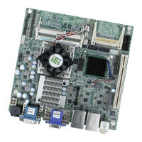
IEI Technology KINO-PVN-D4251-R10 User Manual (146 pages)
Mini ITX SBC with Intel Atom D525 1.8GHz/1MB L2 cache,. DDR3, VGA/ DVI-I DL/ HDMI by Nvidia GT218,
Brand:
IEI Technology
| Category:
Single board computers
| Size: 6.07 MB
Table of Contents
Table of Contents
4
Introduction
15
Introduction
16
Figure 1-1: KINO-PVN-D5251/D4251 Front View
16
Figure 1-2: KINO-PVN-D5251/D4251 Solder View
16
Connectors
18
Figure 1-3: Connectors Front View
18
Figure14: Connectors Solder View
18
Dimensions
19
Figure 1-5: KINO-PVN-D5251/D4251 Dimensions (MM)
19
Data Flow
20
Figure 1-6: Data Flow Block Diagram
20
Technical Specifications
21
Table 1-1: Technical Specifications
23
Unpacking
24
Anti-Static Precautions
25
Unpacking Precautions
25
Packing List
26
Optional Items
27
Connectors
28
Peripheral Interface Connectors
29
KINO-PVN-D5251/D4251 Layout
29
Figure 3-1: Connector and Jumper Locations Front View
29
Figure32: Connector and Jumper Locations Solder View
29
Peripheral Interface Connectors
30
Table 3-1: Peripheral Interface Connectors
30
External Interface Panel Connectors
31
Internal Peripheral Connectors
31
Power Connector
31
Table 3-2: Rear Panel Connectors
31
Table 3-3: 12 V Power Connector Pinouts
31
Compactflash® Slot
32
Figure 3-3: 12 V Power Connector
32
Figure 3-4: Compactflash® Slot Location
32
Digital I/O Connector
33
Figure 3-5: Digital I/O Connector Locations
33
Table 3-4: Compactflash® Slot Pinouts
33
Fan Connector (CPU)
34
Figure 3-6: CPU Fan Connector Location
34
Table 3-5: Digital I/O Connector Pinouts
34
Table 3-6: CPU Fan Connector Pinouts
34
Flash SPI ROM (GT218)
35
Front Panel Connector
35
Figure 3-7: Flash SPI ROM (GT218) Connector Location
35
Table 3-7: Flash SPI ROM (GT218) Connector Pinouts
35
Keyboard/Mouse Connector
36
Figure 3-8: Front Panel Connector Location
36
Figure 3-9: Keyboard/Mouse Connector Location
36
Table 3-8: Front Panel Connector Pinouts
36
Parallel Port Connector
37
Figure 3-10: Parallel Port Connector Location
37
Table 3-9: Keyboard/Mouse Connector Pinouts
37
Pcie Mini Card Slot
38
Figure 3-11: Pcie Mini Card Slot Location
38
Table 3-10: Parallel Port Connector Pinouts
38
SATA Drive Connectors
39
Figure 3-12: SATA Drive Connector Locations
39
Table 3-11: Pcie Mini Card Slot Pinouts
39
SATA Power Connector
40
Figure 3-13: SATA Power Connector Locations
40
Table 3-12: SATA Drive Connector Pinouts
40
Table 3-13: SATA Power Connector Pinouts
40
Serial Port Connectors (RS-232)
41
Figure 3-14: SATA Power Connector Locations
41
Figure 3-15: Serial Port (COM1) Connector Pinout Locations
41
Table 3-14: SATA Power Connector Pinouts
41
Serial Port Connector (RS-232)
42
Figure 3-16: Serial Port (COM3) Connector Pinout Locations
42
Figure 3-17: Serial Port (COM2) Connector Location
42
Table 3-15: Serial Port Connector Pinouts
42
Smbus Connector
43
Figure 3-18: Smbus Connector Locations
43
Table 3-16: Serial Port (COM2) Connector Pinouts
43
Table 3-17: Smbus Connector Pinouts
43
SPI Flash Connector
44
USB Connectors
44
Figure 3-19: SPI Flash Connector
44
Table 3-18: SPI Flash Connector Pinouts
44
External Peripheral Interface Connector Panel
45
Figure 3-20: USB Connector Pinout Locations
45
Table 3-19: USB Port Connector Pinouts
45
Audio Connector
46
Ethernet and USB Connector
46
Figure 3-21: KINO-PVN-D5251/D4251 External Peripheral Interface Connector
46
Figure 3-22: Audio Connector
46
Figure 3-23: RJ-45 Ethernet Connector
47
Table 3-20: LAN Pinouts
47
Table 3-21: RJ-45 Ethernet Connector Leds
47
Power Connector
48
Serial Port Connector
48
Table 3-22: USB Pinouts
48
Table 3-23: Power Connector Pinouts
48
VGA+DVI Port Connector
49
Figure 3-24: VGA Connector
49
Table 3-24: Serial Port Pinouts
49
Table 3-25: VGA Connector Pinouts
50
Table 3-26: DVI Connector Pinouts
50
Installation
51
Anti-Static Precautions
52
Installation Considerations
53
Installation Notices
53
Unpacking
54
So-DIMM Installation
54
SO-DIMM Installation
55
Figure 4-1: SO-DIMM Installation
55
Figure4-2: SO-DIMM Connector Location
55
Compactflash® Installation
56
Figure 4-3: Compactflash® Card Installation
56
Jumper Settings
57
AT/ATX Power Select Jumper Settings
57
Table 4-1: Jumpers
57
Clear CMOS Jumper
58
Figure 4-4: AT/ATX Power Select Jumper Location
58
Table 4-2: AT/ATX Power Select Jumper Settings
58
Compactflash® Card Setup Jumper
59
Figure 4-5: Clear CMOS Jumper
59
Table 4-3: Clear CMOS Jumper Settings
59
Serial Port Setting Jumper
60
Figure 4-6: Compactflash® Setup Jumper Location
60
Figure 4-7: Serial Port Jumper Locations
60
Chassis Installation
61
Airflow
61
Motherboard Installation
61
Internal Peripheral Device Connections
61
AT/ATX Power Connection
61
Figure 4-8: Power Cable to Motherboard Connection
62
Single RS-232 Cable with Slot Bracket
63
Figure 4-9: Connect Power Cable to Power Supply
63
External Peripheral Interface Connection
64
Figure 4-10: Single RS-232 Cable Installation
64
Audio Connector
65
Figure 4-11: Audio Connector
65
LAN Connection (Dual Connector)
66
Serial Device Connection
66
Figure 4-12: LAN Connection
66
USB Connection (Quad Connector)
67
Figure 4-13: Serial Device Connector
67
VGA Monitor Connection
68
Figure 4-14: USB Connector
68
DVI Display Device Connection
69
Figure 4-15: VGA Connector
69
Software Installation
70
Figure 4-16: DVI Connector
70
Figure 4-17: Introduction Screen
71
Figure 4-18: Available Drivers
72
Figure 4-19: Graphics Driver Installation Reminder
73
Bios Screens
74
Introduction
75
Starting Setup
75
Using Setup
75
Getting Help
76
Unable to Reboot after Configuration Changes
76
BIOS Menu Bar
76
Main
77
Advanced
78
ACPI Settings
79
CPU Configuration
80
SATA Configuration
81
USB Configuration
82
Super IO Configuration
83
Serial Port 1 Configuration
84
Parallel Port Configuration
88
H/W Monitor
90
Serial Port Console Redirection
92
Chipset
93
Host Bridge Configuration
94
South Bridge Configuration
95
Boot
97
Security
99
Exit
100
ABIOS Options
102
B One Key Recovery
105
One Key Recovery Introduction
106
Figure B-1: IEI One Key Recovery Tool Menu
106
System Requirement
107
Supported Operating System
108
Setup Procedure for Windows
109
Hardware and BIOS Setup
109
Create Partitions
110
Figure B-2: Launching the Recovery Tool
110
Figure B-3: Recovery Tool Setup Menu
111
Figure B-4: Command Mode
111
Figure B-5: Partition Creation Commands
112
Install Operating System, Drivers and Applications
113
Build-Up Recovery Partition
114
Figure B-6: Launching the Recovery Tool
114
Figure B-7: System Configuration for Windows
114
Figure B-8: Build-Up Recovery Partition
115
Figure B-9: Press any Key to Continue
115
Create Factory Default Image
116
Figure B-10: Press F3 to Boot into Recovery Mode
116
Figure B-11: Recovery Tool Menu
116
Figure B-12: about Symantec Ghost Window
117
Figure B-13: Symantec Ghost Path
117
Figure B-14: Select a Local Source Drive
118
Figure B-15: Select a Source Partition from Basic Drive
118
Figure B-16: File Name to Copy Image to
119
Figure B-17: Compress Image
119
Figure B-18: Image Creation Confirmation
120
Figure B-19: Image Creation Complete
120
Figure B-20: Image Creation Complete
120
Setup Procedure for Linux
121
Figure B-21: Press any Key to Continue
121
Figure B-22: Partitions for Linux
122
Figure B-23: System Configuration for Linux
123
Figure B-24: Access Menu.lst in Linux (Text Mode)
123
Recovery Tool Functions
124
Figure B-25: Recovery Tool Menu
124
Figure B-26: Recovery Tool Main Menu
125
Factory Restore
126
Figure B-27: Restore Factory Default
126
Figure B-28: Recovery Complete Window
126
Backup System
127
Figure B-29: Backup System
127
Figure B-30: System Backup Complete Window
127
Restore Your Last Backup
128
Figure B-31: Restore Backup
128
Figure B-32: Restore System Backup Complete Window
128
Manual
129
Figure B-33: Symantec Ghost Window
129
Other Information
130
Using AHCI Mode or Ali M5283 / VIA VT6421A Controller
130
System Memory Requirement
132
C Terminology
133
D Digital I/O Interface
137
Introduction
138
Dio Connector Pinouts
138
Assembly Language Samples
139
Enable the DIO Input Function
139
Enable the DIO Output Function
139
E Watchdog Timer
140
F Hazardous Materials Disclosure
143
Hazardous Materials Disclosure Table for IPB Products Certified as Rohs Compliant under 2002/95/EC Without Mercury
144
Advertisement
Advertisement
Related Products
IEI Technology KINO-PVN-D5251
IEI Technology KINO-PVN-D4251
IEI Technology KINO-PVN-D5251-R10
IEI Technology KINO-PV-D5253-D4253
IEI Technology KINO-DAL-N1
IEI Technology KINO-DAL-E3W2
IEI Technology KINO-DAL-E1W2
IEI Technology KINO-DBT-E38XX1-R10
IEI Technology KINO-DAL
IEI Technology KINO-CV-D25501-R10
IEI Technology Categories
Motherboard
Touch Panel
Computer Hardware
Single board computers
Desktop
More IEI Technology Manuals
Login
Sign In
OR
Sign in with Facebook
Sign in with Google
Upload manual
Upload from disk
Upload from URL