Sign In
Upload
Manuals
Brands
IEI Technology Manuals
Single board computers
KINO-PV-D5253-D4253
IEI Technology KINO-PV-D5253-D4253 Manuals
Manuals and User Guides for IEI Technology KINO-PV-D5253-D4253. We have
1
IEI Technology KINO-PV-D5253-D4253 manual available for free PDF download: User Manual
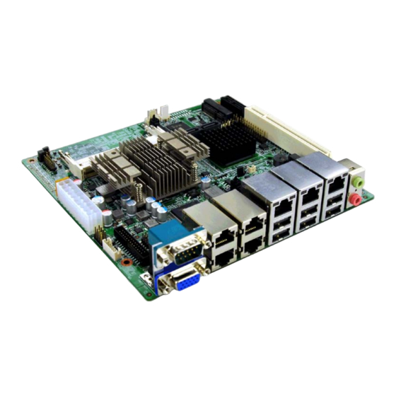
IEI Technology KINO-PV-D5253-D4253 User Manual (139 pages)
Mini-ITX Motherboard with Intel Atom Processor D525/D425, DDR 3, VGA,
Brand:
IEI Technology
| Category:
Single board computers
| Size: 3.86 MB
Table of Contents
Table of Contents
4
Introduction
13
Introduction
14
Benefits
14
Figure 1-1: KINO-PV-D5253/D4253
14
Features
15
Connectors
15
Figure 1-2: Connectors
15
Dimensions
16
Figure 1-3: Dimensions (MM)
16
Data Flow
17
Technical Specifications
17
Figure 1-4: Data Flow Diagram
17
Table 1-1: Technical Specifications
19
Packing List
20
Anti - Static Precautions
21
Unpacking Precautions
21
Packing List
22
Optional Items
23
Table 2-1: Packing List
23
Table 2-2: Optional Items
24
Connectors
25
Peripheral Interface Connectors
26
Layout
26
Figure 3-1: Connectors and Jumpers
26
External Interface Panel Connectors
27
Table 3-1: Internal Peripheral Connectors
27
Internal Peripheral Connectors
28
Battery Connector
28
Table 3-2: External Peripheral Connectors
28
CPU Fan Connector
29
Figure 3-2: Battery Connector Location
29
Table 3-3: Battery Connector Pinouts
29
System Fan Connector
30
Figure 3-3: CPU Fan Connector Location
30
Table 3-4: CPU Fan Connector Pinouts
30
Standard ATX Power Connector
31
Figure 3-4: System Fan Connector Location
31
Table 3-5: System Fan Connector Pinouts
31
Digital I/O Connector
32
Figure 3-5: ATX Power Input Connector Location
32
Front Panel Connector
33
Figure 3-6: Digital I/O Connector Locations
33
Table 3-6: Digital I/O Connector Pinouts
33
Memory Slot
34
Figure 3-7: Front Panel Connector Location
34
Table 3-7: Front Panel Connector Pinouts
34
Parallel Port Connector
35
Figure 3-8: Memory Card Slot Location
35
RS-232/422/485 Serial Port Connector
36
Figure 3-9: Parallel Port Connector Location
36
Table 3-8: Parallel Port Connector Pinouts
36
Figure 3-10: RS-232/422/485 Serial Port Connector
37
SATA Drive Connectors
38
Figure 3-11: SATA Drive Connector Location
38
Table 3-9: RS-232/422/485 Serial Port Connector Pinouts
38
Smbus Connector
39
Figure 3-12: Smbus Connector Location
39
Table 3-10: SATA Drive Connector Pinouts
39
SPI Flash Connector
40
Figure 3-13: SPI Flash Connector
40
Table 3-11: Smbus Connector Pinouts
40
Table 3-12: SPI Flash Connector
40
USB Connectors
41
TPM Connector
41
Figure 3-14: USB Connector Pinout Locations
41
Table 3-13: USB Port Connector Pinouts
41
Keyboard/Mouse Wafer
42
Figure 3-15: TPM Connector
42
Table 3-14: TPM Connector Pinouts
42
Pcie Mini Card Slot
43
Figure 3-16: Keyboard/Mouse Connector Location
43
Table 3-15: Keyboard Connector Pinouts
43
External Peripheral Interface Connector Panel
44
Figure 3-17: Pcie Mini Card Slot Location
44
Figure 3-18: External Peripheral Interface Connector
44
Audio Connector
45
LAN Connector
45
Figure 3-19: Audio Connector
45
Table 3-16: LAN Pinouts
45
Serial Port Connectors (COM1)
46
Serial Port Connectors (COM1_2, COM3_4)
46
Figure 3-20: Serial Port Pinouts
46
Table 3-17: Serial Port Pinouts
46
USB Connector
47
VGA Connector
47
Table 3-18: Serial Port Pinouts
47
Table 3-19: USB Port Pinouts
47
Figure 3-21: VGA Connector
48
Table 3-20: VGA Connector Pinouts
48
Installation
49
Anti - Static Precautions
50
Installation Considerations
50
Basic Installation
52
SO-DIMM Installation
52
Motherboard Installation
52
Figure 4-1: SO-DIMM Installation
52
Jumper Settings
53
Clear CMOS Jumper
53
Table 4-1: Jumpers
53
USB6, 7 Power Jumper
54
Figure 4-2: Clear BIOS Jumper Location
54
Table 4-2: Clear BIOS Jumper Settings
54
Table 4-3: USB6, 7 Power Jumper Settings
54
COM 6 Function Select Jumper
55
Figure 4-3: USB6, 7 Power Jumper Location
55
Table 4-4: COM 6 Function Select Jumper Settings
55
Internal Peripheral Device Connections
56
SATA Drive Connection
56
Figure 4-4: COM 6 Function Select Jumper Location
56
Figure 4-5: SATA Drive Cable Connection
57
Single RS-232 Cable (W/O Bracket)
58
Figure 4-6: SATA Power Drive Connection
58
External Peripheral Interface Connection
59
Audio Connector
59
Figure 4-7: Single RS-232 Cable Installation
59
LAN Connection
60
Figure 4-8: Audio Connector
60
Serial Device Connection
61
Figure 4-9: LAN Connection
61
USB Device Connection
62
Figure 4-10: Serial Device Connector
62
VGA Monitor Connection
63
Figure 4-11: USB Connector
63
Software Installation
64
Figure 4-12: VGA Connector
64
Bios
65
Introduction
66
Starting Setup
66
Using Setup
66
Getting Help
67
Unable to Reboot after Configuration Changes
67
BIOS Menu Bar
67
Table 5-1: BIOS Navigation Keys
67
Main
68
BIOS Menu 1: Main
68
Advanced
69
ACPI Settings
69
BIOS Menu 2: Advanced
69
Trusted Computing
70
BIOS Menu 3: ACPI Settings
70
CPU Configuration
71
BIOS Menu 4: TPM Configuration
71
BIOS Menu 5: CPU Configuration
72
SATA Configuration
73
BIOS Menu 6: IDE Configuration
73
USB Configuration
74
BIOS Menu 7: USB Configuration
74
Super IO Configuration
75
BIOS Menu 8: Super IO Configuration
75
Serial Port N Configuration
76
BIOS Menu 9: Serial Port N Configuration Menu
76
Parallel Port Configuration
81
BIOS Menu 10: Parallel Port Configuration Menu
81
H/W Monitor
82
BIOS Menu 11: Hardware Health Configuration
82
Serial Port Console Redirection
83
BIOS Menu 12: Serial Port Console Redirection
84
Chipset
85
BIOS Menu 13: Chipset
85
Host Bridge Configuration
86
BIOS Menu 14: Host Bridge Chipset Configuration
86
South Bridge Configuration
87
BIOS Menu 15: South Bridge Chipset Configuration
87
Intel IGD SWSCI Opregion
89
BIOS Menu 16: South Bridge Chipset Configuration
89
Boot
90
BIOS Menu 17: Boot
90
Security
91
BIOS Menu 18: Security
92
Save &Exit
93
BIOS Menu 19:Exit
93
A BIOS Options
95
B Terminology
98
C One Key Recovery
102
Figure C-1: IEI One Key Recovery Tool Menu
103
Figure C-2: Launching the Recovery Tool
107
Figure C-3: Recovery Tool Setup Menu
108
Figure C-4: Command Mode
108
Figure C-5: Partition Creation Commands
109
Figure C-6: Launching the Recovery Tool
111
Figure C-7: System Configuration for Windows
111
Figure C-8: Build-Up Recovery Partition
112
Figure C-9: Press any Key to Continue
112
Figure C-10: Press F3 to Boot into Recovery Mode
113
Figure C-11: Recovery Tool Menu
113
Figure C-12: about Symantec Ghost Window
114
Figure C-13: Symantec Ghost Path
114
Figure C-14: Select a Local Source Drive
115
Figure C-15: Select a Source Partition from Basic Drive
115
Figure C-16: File Name to Copy Image to
116
Figure C-17: Compress Image
116
Figure C-18: Image Creation Confirmation
117
Figure C-19: Image Creation Process
117
Figure C-20: Image Creation Complete
117
Figure C-21: Press any Key to Continue
118
Figure C-22: Partitions for Linux
119
Figure C-23: System Configuration for Linux
120
Figure C-24: Access Menu.lst in Linux (Text Mode)
120
Figure C-25: Recovery Tool Menu
121
Figure C-26: Recovery Tool Main Menu
122
Figure C-27: Restore Factory Default
123
Figure C-28: Recovery Complete Window
123
Figure C-29: Backup System
124
Figure C-30: System Backup Complete Window
124
Figure C-31: Restore Backup
125
Figure C-32: Restore System Backup Complete Window
125
Figure C-33: Symantec Ghost Window
126
D Watchdog Timer
130
E Digital I/O Interface
133
F Hazardous Materials Disclosure
136
Advertisement
Advertisement
Related Products
IEI Technology KINO-PVN-D5251
IEI Technology KINO-PVN-D4251
IEI Technology KINO-PVN-D4251-R10
IEI Technology KINO-PVN-D5251-R10
IEI Technology KINO-780EB
IEI Technology KINO-DAL-E2W2
IEI Technology KINO-DBT-J1900-R10
IEI Technology KINO-KX
IEI Technology KINO-CV-N26001-R10
IEI Technology KINO-TGL-U-C-R10
IEI Technology Categories
Motherboard
Touch Panel
Computer Hardware
Single board computers
Desktop
More IEI Technology Manuals
Login
Sign In
OR
Sign in with Facebook
Sign in with Google
Upload manual
Upload from disk
Upload from URL