Sign In
Upload
Manuals
Brands
IEI Technology Manuals
Single board computers
DRPC-230-ULT5-C/8G/S
IEI Technology DRPC-230-ULT5-C/8G/S Manuals
Manuals and User Guides for IEI Technology DRPC-230-ULT5-C/8G/S. We have
1
IEI Technology DRPC-230-ULT5-C/8G/S manual available for free PDF download: User Manual
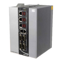
IEI Technology DRPC-230-ULT5-C/8G/S User Manual (117 pages)
Brand:
IEI Technology
| Category:
Single board computers
| Size: 3 MB
Table of Contents
Table of Contents
5
Introduction
11
Overview
12
Figure 1-1: DRPC-230-ULT5 Series
12
Model Variations
13
Features
13
Table 1-1: DRPC-230-ULT5 Model Variations
13
Front Panel
14
Figure 1-2: Front Panel
14
Top Panel
15
Figure 1-3: Top Panel
15
Technical Specifications
16
Table 1-2: Technical Specifications
17
Dimensions
18
DRPC-230-ULT5-I5/8G/S & DRPC-230-ULT5-C/8G/S
18
Figure 1-4: DRPC-230-ULT5-I5/8G/S & DRPC-230-ULT5-C/8G/S Dimensions (MM)
18
DRPC-230-ULT5-I5/8G
19
Figure 1-5: DRPC-230-ULT5-I5/8G Dimensions (MM)
19
Unpacking
20
Anti-Static Precautions
21
Unpacking Precautions
21
Packing List
22
Optional Items
23
Installation
25
Installation Precautions
26
High Surface Temperature
26
Internal Access Panel Removal
27
Figure 3-1: Internal Access Panel Retention Screws
27
Hdd Installation
28
Figure 3-2: HDD Installation
28
Pcie Mini Card Installation
29
Figure 3-3: Pcie Mini Slot Location
29
Figure 3-4: Removing the Pcie Mini Card Retention Screw
29
Figure 3-5: Inserting the Pcie Mini Card into the Slot at an Angle
30
Figure 3-6: Securing the Pcie Mini Card
30
Pcie Mini Card Slot Pinouts (MINI_PCIE1)
31
Table 3-1: Pcie Mini Card Slot (MINI_PCIE1) Pinouts
31
Sim Card Installation
32
Figure 3-7: Unlock SIM Card Slot Cover
32
Figure 3-8: Unlock SIM Card Slot Cover
32
Figure 3-9: SIM Card Installation
33
Figure 3-10: Lock SIM Card Slot Cover
33
Module Installation
34
Figure 3-11: M.2 Slot Location
34
Figure 3-12: Inserting the M.2 Module into the Slot at an Angle
34
Module Slot Pinouts (M2_A1)
35
Figure 3-13: Securing the M.2 Module
35
Table 3-2: M.2 Module Slot (M2_A1) Pinouts
36
Rs-232/422/485 Serial Port Connection
37
Serial Port Connection
37
Table 3-3: RS-232/422/485 DB-9 Connector Pinouts
37
Table 3-4: RS-232 RJ-45 Connector Pinouts
37
Lan Connection
38
Figure 3-14: RJ-45 Ethernet Connector
38
Table 3-5: LAN Pinouts
38
Table 3-6: RJ-45 Ethernet Connector Leds
38
At/Atx Mode Selection
39
Figure 3-15: AT/ATX Switch Location
39
Din Rail Mounting
40
Figure 3-16: DIN Rail Mounting Bracket Preparation
40
Figure 3-17: DIN Rail Mounting Bracket Installation
40
Figure 3-18: Attach the Mounting Bracket to the DIN Rail
41
Figure 3-19: Secure the Mounting Bracket
41
Power -O N Procedure
42
Installation Checklist
42
Terminal Block Pinouts
42
Table 3-7: 3-Pin Power Terminal Block Pinouts
42
Power-On Procedure
43
Figure 3-20: Power-On
43
Available Drivers
44
Driver Download
44
Figure 3-21: IEI Resource Download Center
44
Troubleshooting and Maintenance
46
System Maintenance Overview
47
System Troubleshooting
47
The System Doesn't Turn on
47
The System Doesn't Boot up
48
More Troubleshooting
48
Maintenance
48
Clear CMOS
49
Figure 4-1: Clear CMOS Button Location
49
ME Override Jumper
50
Figure 4-2: ME Override Jumper Location
50
Table 4-1: ME Override Jumper Settings
50
Bios
51
Introduction
52
Starting Setup
52
Using Setup
52
Getting Help
53
Unable to Reboot after Configuration Changes
53
BIOS Menu Bar
53
Table 5-1: BIOS Navigation Keys
53
Main
54
Advanced
55
CPU Configuration
56
PCH-FW Configuration
58
PTT Configuration
59
Trusted Computing
60
ACPI Settings
61
RTC Wake Settings
62
Iwdd H/W Monitor
63
Smart Fan Mode Configuration
64
F81866 Super IO Configuration
66
Serial Port N Configuration
67
Serial Port Console Redirection
68
Legacy Console Redirection Settings
69
Console Redirection Settings
70
USB Configuration
72
CSM Configuration
73
Nvme Configuration
74
IEI Feature
75
Chipset
76
System Agent (SA) Configuration
76
Memory Configuration
77
Graphics Configuration
78
PCH-IO Configuration
80
PCI Express Configuration
82
SATA and RST Configuration
84
Security
86
Boot
87
Save & Exit
89
Interface Connectors
91
Peripheral Interface Connectors
92
Figure 6-1: Main Board Layout Diagram
92
Internal Peripheral Connectors
93
Battery Connector (BAT1)
93
Table 6-1: Peripheral Interface Connectors
93
Table 6-2: Battery Connector (BAT1) Pinouts
93
Digital I/O Connector (DIO1)
94
Fan Connectors (CPU/FAN1, CPU/FAN2)
94
Internal Power Connector (PWR1)
94
Table 6-3: Digital I/O Connector (DIO1) Pinouts
94
Table 6-4: Fan Connector (CPU/FAN1, CPU/FAN2) Pinouts
94
Table 6-5: Internal Power Connector (PWR1) Pinouts
94
SATA Connector (SATA1)
95
Smbus Connector (SMB1)
95
SPI Flash Connector (JSPI1)
95
Table 6-6: SATA 6Gb/S Connector (SATA1) Pinouts
95
Table 6-7: Smbus Connector (SMB1) Pinouts
95
Table 6-8: SPI Flash Connector (JSPI1) Pinouts
95
TPM Connector (TPM1)
96
USB DOM Connector (DOM1)
96
Table 6-9: TPM Connector (TPM1) Pinouts
96
Table 6-10: USB DOM Connector (DOM1) Pinouts
96
A Regulatory Compliance
97
B Safety Precautions
102
Safety Precautions
103
General Safety Precautions
103
Anti-Static Precautions
104
Explanation of Graphical Symbols
104
Drpc-230-Ult5
104
Product Disposal
105
Maintenance and Cleaning Precautions
106
Maintenance and Cleaning
106
Cleaning Tools
106
C Digital I/O Interface
107
D Watchdog Timer
110
E Error Beep Code
113
Pei Beep Codes
114
Dxe Beep Codes
114
F Hazardous Materials Disclosure
115
Rohs II Directive (2015/863/EU)
116
China Rohs
117
Advertisement
Advertisement
Related Products
IEI Technology DRPC-124-EHL Series
IEI Technology DRPC-124-EHL-JC-R10
IEI Technology DRPC-230-ULT5 Series
IEI Technology DRPC-230-ULT5-i5/8G/S
IEI Technology DRPC-230-ULT5-i5/8G
IEI Technology DRPC-230-ULT5-CE/8G/S
IEI Technology DRPC-240-TGL
IEI Technology DRPC-242-ADL-P Series
IEI Technology DRPC-242-ADL-P-CCS
IEI Technology DRPC-242-ADL-P-i3CS
IEI Technology Categories
Motherboard
Touch Panel
Computer Hardware
Single board computers
Desktop
More IEI Technology Manuals
Login
Sign In
OR
Sign in with Facebook
Sign in with Google
Upload manual
Upload from disk
Upload from URL