Sign In
Upload
Manuals
Brands
HySecurity Manuals
Door Opening System
SlideDriver 30F
HySecurity SlideDriver 30F Manuals
Manuals and User Guides for HySecurity SlideDriver 30F. We have
5
HySecurity SlideDriver 30F manuals available for free PDF download: Programming And Operations Manual, Programming & Operation Manual, Installation Instructions Manual, Manual
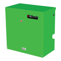
HySecurity SlideDriver 30F Programming And Operations Manual (156 pages)
Vehicular slide gate operator with Smart Touch Controller
Brand:
HySecurity
| Category:
Gate Opener
| Size: 19 MB
Table of Contents
Slidedriver 15, 30F
4
Slidedriver 50VF Site Installation Overview
4
Slidedriver (All Models) 50VF Components
5
Table of Contents
7
Welcome to Hysecurity
12
Contact Information
13
Notices and Bulletins
13
Supplemental Documents
13
Important Safety Information
14
Important Safety Information
27
Emergency Stop Button
28
Emergency Release
28
Power
29
Installing the Earth Ground
29
Site Considerations
30
Wiring AC Power
30
Turning the Power Switch on
31
Wire Sizing and Runs
32
Low Voltage Control Wiring
32
Slidedriver Wiring Charts (Incoming Power)
33
Slidedriver 50VF-Series Wiring Chart (Incoming Power)
35
Performance of 50VF-Series Operators on 1 and 3 Phase, 50 or 60Hz
35
Control Transformer Connections (Non-UPS)
37
Gate Operator Connections (Modular Unit)
37
UPS Backup Power Options
38
DC Power Supply (UPS) Connections
38
AC Power Supply with Hyinverter AC
38
Initial Setup
39
Gate Handing
39
Hydraulic Hose Swap
40
Adjusting the Brake Valves
40
Grounding, Breather Cap Installation & Handing
41
Slidedriver Standard and Slow down Limit Ramps
42
Adjusting the Pressure Relief Valve
43
Modbus RTU in Slidedriver 50VF-Series
44
Emergency Fast Operate (EFO) in Slidedriver 50VF-Series
45
Installing a Push Button Device for Emergency Fast Operate (EFO)
46
Emergency Fast Close Speeds
46
Entrapment Protection
47
Manufacturer's Responsibility
49
Pressure Relief Valve - All Hydraulic Operators
49
Inherent Entrapment Sensor System - Hydraulic Operators (IES)
49
The Inherent Entrapment Sensor (IES)
50
How Software Handles Monitoring External Entrapment Protection Sensors
51
External Entrapment Protection Sensors: What the Installer Needs to Do
51
Table 4: Installer Menu Settings for SENSOR Inputs
53
Supply Power to the Sensors
54
Control Panel Overview
55
Slidedriver Wiring Diagram, D0266 REV B
56
Variable Speed Drive (VFD) Control Box
57
Variable Speed Drive Wiring Diagram, Pre-May 2017
58
Variable Speed Drive Wiring Diagram, May 2017
59
STC Board, Power Supply Board and Display
60
Display & Menu Options
61
Understanding the Display and Keypad
61
Initial Setup
62
Initial Setup Using S.T.A.R.T
63
Menu Mode and the STC Keypad
63
Menu Mode Navigation
64
Run Mode and the STC Keypad
65
Viewing Gate Operator Scrolling Status
65
Stop the Status Display Scrolling
66
Change the Contrast on 7 Segment Displays
66
Display Power Saving Mode
67
Check the Software Version
67
Check Time and Date
67
User Menu
67
Installer Menu
70
Setting the Close Timer
77
Test the Operator
78
STC Inputs & Wiring
79
Overview of the STC and Power Supply Board
80
Integrating with Security Systems and Hynet™ Gateway
81
Smart Touch Controller Inputs
82
STC Terminal Inputs
82
Connecting Accessory Devices
85
User Relays - Programming Procedure
86
Hy8Relay Module Option
88
Bi-Parting & Dual Gate Systems
89
Connecting an Interlocked Pair (Dual Gate)
89
Dual Gate Wiring Connections
90
Dual or Sequenced Gates: Power, Software & Accessory Requirements
91
Programming a Dual Gate (Interlocked Pair)
91
Connecting Sequenced Gates
92
Sequenced Gate: Configuration #1
94
Sequenced Gate: Configuration #2
95
Ehicle D Etector I Nstallation and L Oop L Ayouts
97
Anti-Tailgate Mode (Closing Logic)
97
Tailgate Alert
97
Vehicle Detectors and the Smart Touch Controller
98
Hy5B Installation
98
Test the Vehicle Loop
98
Check the Version of Software
99
Install Hy5B Vehicle Detectors
99
Vehicle Detector and Loop Fault Diagnostics
101
Installing Standard 11-Pin Box Type Vehicle Detectors
104
Loop Layout: One Lane, Bi- or Single-Directional
105
Photo Eye Installation
106
Photo Eyes (Non-Contact) Installation
107
Compatibility
107
Installation
108
Configuration
108
Photo Eye Connections: Smart Touch & Smart DC Controllers
109
Photo Eye Function
109
Retro-Reflective Photo Eye Systems
110
Using Photo Eye Sensors Instead of Vehicle Loops
110
Photo Eye Alignment Feature
112
Installing Gate Edge Sensors
113
Compatibility
114
Installation
114
Edge Sensor Installation Tips
114
Gate Edge Function
115
Troubleshooting
116
System Diagnostic Messages
116
Typical Problems and Troubleshooting Procedures
117
Table 8: Troubleshooting Codes
118
Access the Event Log through the User Menu
129
Electrical Issues
130
AC-Powered Gate Operators
130
Electrical Controls
130
Mechanical Issues
131
Hydraulic Issues
131
General Maintenance
132
Smart Touch Analyze and Retrieve Tool (S.T.A.R.T.)
132
What You Need
132
Installing S.T.A.R.T. Software
132
Ssoftware Maintenance
133
Electrical Controls
133
Clock Battery Replacement
133
Mechnical Controls
134
Stopping the Gate
134
Starting the Gate
134
Mechanical Maintenance
134
Drive Rail
135
Drive Wheel Spring Tension (Adjustment of Manual Release)
136
Grooved Drive Rail
137
Drive Wheel Assembly
138
Hydraulic System Maintenance
139
Brake Valve Adjustments
140
Pressure Relief Valve Adjustments
140
Open Valve
140
Slidedriver Operator Maintenance Schedule
141
Wiring Hysecurity Sensors: Smart Touch
142
Wiring Tips for SENSOR COM Terminal: Smart Touch
143
Menu Mode Navigational Tips
143
Smart Touch: 2 CH Wired Edge with Hy2Nc
144
Smart Touch: Photo Eye Thru Beam (EMX IRB MON)
145
Smart Touch: Photo Eye / Reflective (E3K R10K4)
146
Smart Touch: the Solution, MIM-62 (Multi-Input Module)
147
Smart Touch: Igaze Kit Wiring Diagram
148
Slidedriver Installer Checklist
149
Appendix A - French Translations
151
Specifications
156
Advertisement
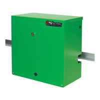
HySecurity SlideDriver 30F Programming And Operations Manual (132 pages)
with Smart Touch Controller
Brand:
HySecurity
| Category:
Gate Opener
| Size: 11 MB
Table of Contents
Table of Contents
7
Welcome to Hysecurity
11
Contact Information
12
Notices and Bulletins
12
Supplemental Documents
12
Important Safety Information
13
Safety - Additional Installer Responsibility
14
Identifying Gate Operator Category and Usage Class
15
Safety - Additional Installer's Responsibility, Continued
16
Safety - Owner/User Responsibility
17
Hazardous Materials and Proper Disposal
17
Emergency Stop Button
18
Emergency Release
18
Safety Notices
19
Common Industrial Symbols
19
Power
21
Installing the Earth Ground
21
Site Considerations
22
Wiring AC Power
22
Turning the Power Switch on
23
Wire Sizing and Runs
24
Low Voltage Control Wiring
24
Slidedriver Wiring Charts (Incoming Power)
25
Slidedriver 50VF-Series Wiring Chart (Incoming Power)
27
Performance of 50VF-Series Operators on 1 and 3 Phase, 50 or 60Hz
27
Control Transformer Connections (Non-UPS)
29
Gate Operator Connections (Modular Unit)
29
DC Power Supply (UPS) Connections
30
AC Power Supply with Hyinverter AC
30
Initial Setup
31
Gate Handing
31
Hydraulic Hose Swap
32
Adjusting the Brake Valves
32
Grounding, Breather Cap Installation & Handing
33
Slidedriver Slow down Limit Ramps
34
Adjusting the Pressure Relief Valve
35
Modbus RTU in Slidedriver 50VF-Series
36
Emergency Fast Operate (EFO) in Slidedriver 50VF-Series
37
Installing a Push Button Device for Emergency Fast Operate (EFO)
38
Emergency Fast Close Speeds
38
Entrapment Protection
39
Manufacturer's Responsibility
39
Pressure Relief Valve - All Hydraulic Operators
39
Inherent Entrapment Sensor System - Hydraulic Operators (IES)
40
The Inherent Entrapment Sensor (IES)
40
How Software Handles Monitoring External Entrapment Protection Sensors
41
External Entrapment Protection Sensors: What the Installer Needs to Do
41
Supply Power to the Sensors
44
C Ontrol P Anel O Verview
45
Slidedriver Wiring Diagram, D0266 REV B
46
Variable Speed Drive (VFD) Control Box
47
Variable Speed Drive Wiring Diagram
48
STC Board, Power Supply Board and Display
49
D Isplay & M Enu O Ptions
51
Initial Setup
51
Understanding the Display and Keypad
51
Menu Mode and the STC Keypad
52
Menu Mode Navigation
52
Run Mode and the STC Keypad
53
Viewing Operator Status Displays
53
Stop the Status Display Scrolling
54
Change the Contrast on 7 Segment Displays
54
Check the Software Version
54
Check Time and Date
55
User Menu
55
User Menu: Table 6
56
Installer Menu
58
Installer Menu: Table 7
58
Setting the Close Timer
64
Test the Operator
65
STC Inputs & Wiring
67
Overview of the STC and Power Supply Board
68
Integrating with Security Systems and Hynet™ Gateway
69
Smart Touch Controller Inputs
70
STC Terminal Inputs
70
User Relays - Programming Procedure
73
Programmable User Relays: Table 8
73
Hy8Relay Module Option
76
Bi-Parting & Dual Gate Systems
77
Connecting an Interlocked Pair (Dual Gate)
77
Dual Gate Wiring Connections
78
Dual or Sequenced Gates: Power, Software & Accessory Requirements
79
Programming a Dual Gate (Interlocked Pair)
79
Connecting Sequenced Gates
80
Sequenced Gate: Configuration #1
82
Sequenced Gate: Configuration #2
83
Ehicle D Etector L Ogic
85
Anti-Tailgate Mode (Closing Logic)
85
Tailgate Alert
85
Vehicle Detector Installation: HY-5A
86
Connecting HY-5A Vehicle Detectors
87
View Call Level in Real Time
88
Installing Standard 11-Pin Box Type Vehicle Detectors
89
I Nstallation and
85
Photo Eye Installation
91
Photo Eyes (Non-Contact) Installation
92
Compatibility
92
Installation
92
Configuration
93
Photo Eye Connections: Smart Touch & Smart DC Controllers
93
Photo Eye Function
93
Retro-Reflective Photo Eye Systems
94
Using Photo Eye Sensors Instead of Vehicle Loops
95
Photo Eye Alignment Feature
96
Installing Gate Edge Sensors
97
Compatibility
98
Installation
98
Gate Edge Function
98
Troubleshooting
99
System Diagnostic Messages
99
Troubleshooting Codes: Table 9
100
Access the Event Log through the User Menu
105
Electrical Issues
106
AC-Powered Gate Operators
106
Mechanical Issues
107
Hydraulic Issues
107
Typical Problems and Troubleshooting Procedures
108
General Maintenance
109
Smart Touch Analyze and Retrieve Tool (S.T.A.R.T.)
109
What You Need
109
Installing S.T.A.R.T. Software
109
Software Maintenance
110
Electrical Controls
110
Clock Battery Replacement
110
Mechnical Controls
111
Stopping the Gate
111
Starting the Gate
111
Mechanical Maintenance
111
Drive Rail
112
Drive Wheel Spring Tension (Adjustment of Manual Release)
113
Grooved Drive Rail
114
Drive Wheel Assembly
115
Hydraulic System Maintenance
116
Brake Valve Adjustments
117
Pressure Relief Valve Adjustments
117
Open Valve
117
Slidedriver Operator Maintenance Schedule
118
Wiring Hysecurity Sensors: Smart Touch
119
Wiring Tips for SENSOR COM Terminal: Smart Touch
120
Menu Mode Navigational Tips
120
Smart Touch: Wired Edge Sensor with GEM (-104)
121
Smart Touch: Photo Eye Thru Beam (EMX IRB MON)
122
Smart Touch: Photo Eye / Reflective (E3K R10K4)
123
Smart Touch: the Solution, MIM-62 (Multi-Input Module)
124
Smart Touch: Photo Eye / Reflecti-Guard (RG-R)
125
Smart Touch: Wireless Edge, Wireless Gate Link
126
Smart Touch: Wired Edge with GEM-104 & Photo Eye
127
Smart Touch: Wireless Edge Gate Link & Photo Eye
128
Slidedriver Installer Checklist
129
Specifications
132
E Ntrapment P Rotection
132
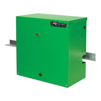
HySecurity SlideDriver 30F Programming & Operation Manual (104 pages)
Smart Touch Controller
Brand:
HySecurity
| Category:
Gate Opener
| Size: 17 MB
Table of Contents
Table of Contents
5
Welcome to Hysecurity
9
Contact Information
10
Notices and Bulletins
10
Supplemental Documents
10
Important Safety Information
11
Safety - Additional Installer Responsibility
12
Safety - Owner/User Responsibility
14
Hazardous Materials and Proper Disposal
14
Identifying Gate Operator Category and Usage Class
15
Choosing Secondary Entrapment Protection
16
Grounding, Breather Cap Installation & Handing
17
Emergency Stop Button
18
Emergency Release
18
Slidedriver Slow down Limit Ramps
19
Safety Notices
20
Common Industrial Symbols
20
Power
21
Installing the Earth Ground
21
Site Considerations
22
Wiring AC Power
22
Turning the Power Switch on
23
Wire Sizing and Runs
24
Low Voltage Control Wiring
24
Slidedriver Wiring Charts (Incoming Power)
25
Slidedriver 50VF-Series Wiring Chart (Incoming Power)
27
Performance of 50VF-Series Operators on 1 and 3 Phase, 50 or 60Hz
27
Control Transformer Connections (Non-UPS)
29
Gate Operator Connections (Modular Unit)
29
DC Power Supply (UPS) Connections
30
Configure the Operator
31
Gate Handing
31
Hydraulic Hose Swap
32
Adjusting the Pressure Relief Valve
32
The Inherent Entrapment Sensor (IES)
34
Manufacturer's Responsibility
34
Pressure Relief Valve - All Hydraulic Operators
34
Inherent Entrapment Sensor - (IES)
35
Modbus RTU in Slidedriver 50VF-Series
35
Emergency Fast Operate (EFO) in Slidedriver 50VF-Series
36
Setting the Emergency Fast Close
36
Installing a Push-Button Device for EFC
36
Emergency Fast Close Speeds
36
Control Panel Overview
37
Slidedriver Wiring Diagram, D0266 REV B
38
Variable Speed Drive (VFD) Control Box
39
Variable Speed Drive Wiring Diagram
40
STC Board, Power Module and Display
41
Display & Menu Options
43
Initial Setup
43
Understanding the Display and Keypad
43
Menu Mode and the STC Keypad
44
Menu Mode Navigation
44
Run Mode and the STC Keypad
45
Viewing Operator Status Displays
45
Stop the Status Display Scrolling
46
Change the Display Contrast
46
Check Time and Date
46
User Menu
47
User Menu: Table 1
47
Installer Menu
49
Installer Menu: Table 2
50
Setting the Close Timer
55
Test the Operator
56
STC Inputs & Wiring
57
STC Input & Wiring
57
Overview of the STC and Power Module
58
Integrating with Security Systems
59
Smart Touch Controller Inputs
60
STC Terminal Inputs
60
Connecting Accessory Devices
62
User Relays - Programming Procedure
63
Hy8Relay Module Option
65
Vehicle Detector Logic
66
Tailgate Alert
66
Anti-Tailgate Mode Selection
66
Vehicle Detector Installation: HY-5A
67
Connecting HY-5A Vehicle Detectors
68
Photo Eyes (Non-Contact) Installation
69
Compatibility
70
Installation
70
Configuration
70
Photo Eye Connections
71
Photo Eye Alignment
72
Monitored Connection
72
Photo Eye Function
72
Dual Gate Systems
73
Connecting an Interlocked Pair (Dual Gate)
73
Dual Gate Wiring Connections
74
Dual or Sequenced Gates: Power, Software & Accessory Requirements
75
Programming a Dual Gate (Interlocked Pair)
75
Connecting Sequenced Gates
76
Sequenced Gate: Configuration #1
78
Sequenced Gate: Configuration #2
79
Troubleshooting
81
System Diagnostic Messages
81
Troubleshooting Codes: Table 3
82
Electrical Issues
87
AC-Powered Gate Operators
87
Mechanical Issues
88
Hydraulic Issues
88
Typical Problems and Troubleshooting Procedures
89
General Maintenance
91
Smart Touch Analyze and Retrieve Tool (S.T.A.R.T.)
91
What You Need
91
Installing S.T.A.R.T. Software
91
Software Maintenance
92
Electrical Controls
93
Clock Battery Replacement
93
Mechnical Controls
93
Stopping the Gate
93
Starting the Gate
93
Mechanical Maintenance
94
Drive Rail
94
Drive Wheel Spring Tension (Adjustment of Manual Release)
95
Grooved Drive Rail
96
Drive Wheel Assembly
97
Hydraulic System Maintenance
98
Brake Valve Adjustments
99
Pressure Relief Valve Adjustments
99
Open Valve
99
Slidedriver Operator Maintenance Schedule
100
Slidedriver Installer Checklist
101
Specifications
104
Advertisement
HySecurity SlideDriver 30F Installation Instructions Manual (10 pages)
Brand:
HySecurity
| Category:
Door Opening System
| Size: 16 MB
Table of Contents
Setup and Assembly
5
Concrete Pad
6
Wiring AC Power
8
Complete the Installation
9
HySecurity SlideDriver 30F Manual (8 pages)
HyNet Gateway SFP 4/1
Brand:
HySecurity
| Category:
Gateway
| Size: 2 MB
Advertisement
Related Products
HySecurity SlideDriver 15
HySecurity SlideDriver 80
HySecurity SlideDriver 40
HySecurity SlideDriver 50VF2/3
HySecurity SlideDriver 200
HySecurity StrongArm 36
HySecurity SlideWinder 38F
HySecurity SlideWinder 38VF
HySecurity SlideWinder 38S
HySecurity SlideWinder 38FS
HySecurity Categories
Gate Opener
Control Systems
Controller
Gateway
Door Opening System
More HySecurity Manuals
Login
Sign In
OR
Sign in with Facebook
Sign in with Google
Upload manual
Upload from disk
Upload from URL