Sign In
Upload
Manuals
Brands
HP Manuals
Measuring Instruments
8753D
HP 8753D Manuals
Manuals and User Guides for HP 8753D. We have
2
HP 8753D manuals available for free PDF download: User Manual, Service Manual
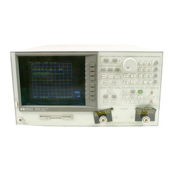
HP 8753D User Manual (678 pages)
Network Analyzer
Brand:
HP
| Category:
Measuring Instruments
| Size: 5 MB
Advertisement
HP 8753D Service Manual (398 pages)
Network Analyzer
Brand:
HP
| Category:
Measuring Instruments
| Size: 5.73 MB
Table of Contents
Section 1
6
Table of Contents
6
Service Equipment and Analyzer Options
8
Principles of Microwave Connector Care
12
Option 1D5, High Stability Frequency Reference
14
Option 002, Harmonic Mode
14
Option 006, 6 Ghz Operation
14
Option 010, Ime Domain
14
Option 1CM, Rack Mount Flange Kit Without Handles
14
Option 1CP, Rack Mount Flange Kit with Handles
14
Analyzer Options Available
14
Option W32
15
Option W34
15
Option W52
15
Option W51
15
Option W31
15
Service and Support Options
15
Option W54
16
Section 2
62
3-2 Adjustments and Correction Constants
67
Ost-Repair Rocedures for H 8753D Option 011
67
A9 CC Jumper Ositions
70
Source Default Correction Constants (Test 44)
71
Source Retune Default Correction Constants (Test 45)
72
Analog Bus Correction Constant (Test 46)
73
RF Output Ower Correction Constants (Test 47)
74
Ower Sensor Calibration Factor Entry
75
Source Correction Routine
78
Source Retune Correction Constants (Test 48)
80
Background Adjustment
81
Display Intensity Correction Constants (Test 49)
81
Maximum Intensity Adjustment
82
Operating Default Intensity Adjustment
83
Sampler Magnitude and Hase Correction Constants (Test 53)
87
Ower Sensor Calibration Factor Entry
88
Update Sampler Correction Constants
88
Cavity Oscillator Frequency Correction Constants (Test 54)
92
Spur Search Rocedure with a Filter
94
Spur Search Rocedure Without a Filter
95
Serial Number Correction Constant (Test 55)
98
Option Numbers Correction Constant (Test 56)
100
Calibration Kit Default Correction Constants (Test 57)
101
Initialize EE Roms (Test 58)
102
EE ROM Backup Disk Rocedure
103
How to Retrieve Correction Constant Data from the EE ROM Backup Disk
104
Focus Adjustment Rocedure
105
Vertical Adjustment Rocedure
105
Vertical Osition and Focus Adjustments
105
Display Degaussing (Demagnetizing)
106
Fractional-N Frequency Range Adjustment
107
Frequency Accuracy Adjustment
110
H 8753D Option 011 with Option 1D5 Only
112
High/Low Band Transition Adjustment
113
Fractional-N Spur Avoidance and FM Sideband Adjustment
115
Source Spur Avoidance Tracking Adjustment
119
Unprotected Hardware Option Numbers Correction Constants
121
How to Load Sequences from Disk
123
How to Set up the Fractional-N Frequency Range Adjustment
123
Sequences for Mechanical Adjustments
123
Section 3
150
Power Supply Troubleshooting
152
Ssembly Replacement Sequence
153
Start here
154
Measure the Post Regulator Voltages
155
If the Green LED on 15 Is Not on Steadily
157
If the Red LED on 15 Is on
158
Inspect the Motherboard
161
If the Green Leds on 8 Are Not Ll on
162
Inspect the Motherboard
166
Error Messages
167
Fan Speeds
170
Fan Troubleshooting
170
Intermittent Problems
171
Section 4
174
Source Troubleshooting
178
Before You Start Troubleshooting
179
Ssembly Replacement Sequence
179
Power
180
RF Output Power Correction Constants (Test 47)
180
Sampler Magnitude and Phase Correction Constants (Test 53)
180
Source Default Correction Constants (Test 44)
180
Phase Lock Error
181
Phase Lock Loop Error Message Check
181
Sampler/Mixer Check
183
Source and 11 Phase Lock Check
184
Reference Check
188
Oscilloscope Method
190
100 Khz Pulses
191
High Band REF Signal
192
PLREF Waveforms
192
Low Band REF Signal
193
Mhz Reference Signal
195
Degree Phase O Set of 2Nd lo Signals in High Band
196
In-Phase 2Nd lo Signals in Low Band
197
L ENREF Line
198
L HB and L LB Lines
199
VCO Range Check with Oscilloscope
200
H MB Line
204
Pulse Generator Check
205
Pulse Generator Check with Spectrum Nalyzer
205
Pulse Generator Check with Oscilloscope
207
Phase Lock Check
208
Phase Lock Check with PLL DI G
209
Raft
209
Section 5
214
Receiver Troubleshooting
216
Receiver Failure Error Messages
217
Ssembly Replacement Sequence
217
Check the R, , and B Inputs
218
Check 2Nd lo
219
Run Internal Tests 18 and 17
219
Troubleshooting When Ll Inputs Look Bad
219
Check 10 by Substitution or Signal Examination
220
Check the 4 Mhz REF Signal
220
Check the 4 Khz Signal
223
Troubleshooting When One or more Inputs Look Good
223
Check 1St lo Signal at Sampler/Mixer
225
Check 2Nd lo Signal at Sampler/Mixer
225
Section 6
226
Accessories Troubleshooting
228
Ssembly Replacement Sequence
229
Inspect the Ccessories
230
Inspect the Error Terms
230
Switch Repeatability
230
Cable Test
231
Verify Shorts and Opens
232
Test Set Troubleshooting
233
Troubleshooting Power Problems in S-Parameter Test Sets
233
Index
238
Section 7
290
Error Terms
292
Rror Terms Can also Serve a Diagnostic Purpose
292
Full Two-Port Rror-Correction Procedure
293
Rror Term Inspection
297
Uncorrected Performance
297
Description
298
Directivity ( DF and DR)
298
Load Match ( LF and LR)
298
Rror Term Descriptions
298
Source Match ( SF and SR)
298
Transmission Tracking ( TF and TR)
298
A Ected Measurements
299
Description
299
Section 8
306
Ow the P 8753D Option 011 Works
310
Theory of Operation
310
A Close Look at the Analyzer's Functional Groups
312
Required Peripheral Equipment
312
Test Set Step Attenuator
312
The Microprocessor
312
The Receiver Block
312
A15 Preregulator
313
Power Supply Theory
313
A8 Post Regulator
314
Line Power Module
314
Preregulated Voltages
314
Voltage Indications: the Green Leds
314
A1 Front Panel
315
Digital Control Theory
315
Probe Power
315
Shutdown Circuit
315
A2 Front Panel Processor
316
A9 CPU/A10 Digital if
316
Main CPU
316
A18 Display
317
A19 Gsp
317
Eeprom
317
Main RAM
317
A16 Rear Panel
318
Source Theory Overview
318
A11 Phase Lock
319
A12 Reference
319
A14/A13 Fractional-N
319
A3 Source
319
A7 Pulse Generator
319
Source Low Band Operation
320
Source Super Low Band Operation
320
Source Igh Band Operation
322
Section 9
332
Assembly Replacement and Post-Repair Procedures
336
Eplacing an Assembly
337
Procedures Described in this Chapter
338
Emoval
339
Eplacement
339
Line Fuse
339
Covers
341
Emoval
343
Front Panel Assembly
343
Eplacement
345
Ear Panel Assembly
347
Emoval
347
Eplacement
349
Emoval
351
Type-N Connector Assembly
351
Eplacement
353
A1 Keyboard
355
Emoval
355
Eplacement
355
A2 Front Panel Interface
357
Emoval
357
Eplacement
357
A3 Source Assembly
359
Emoval
359
Eplacement
359
A4, A5, A6 Samplers and A7 Pulse Generator
361
Emoval
361
Eplacement
361
A8, A10, A11, A12, A13, A14 Card Cage Boards
363
Otice
392
Safety and Licensing
392
Warranty
392
Shipment for Service
395
Instrument Markings
396
Safety Symbols
396
General Safety Considerations
397
Safety Earth Ground
397
Servicing
397
Advertisement
Related Products
HP 8757C
HP 8757E
HP 8756A
HP HP 8753E
HP 8754A
HP Agilent 8757D
HP 8755
HP 8719D
HP 8714C
HP 8720A
HP Categories
Desktop
Laptop
Server
Monitor
Switch
More HP Manuals
Login
Sign In
OR
Sign in with Facebook
Sign in with Google
Upload manual
Upload from disk
Upload from URL