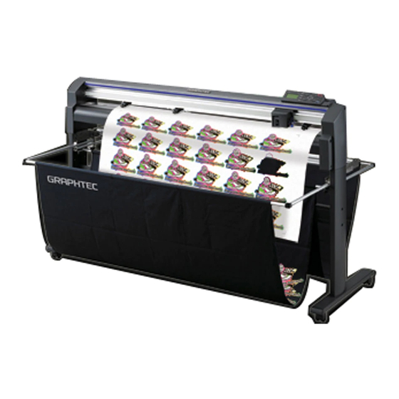
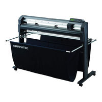
Sign In
Upload
Manuals
Brands
GRAPHTEC Manuals
Plotter
FC8600-60
GRAPHTEC FC8600-60 Manuals
Manuals and User Guides for GRAPHTEC FC8600-60. We have
2
GRAPHTEC FC8600-60 manuals available for free PDF download: User Manual, Service Manual
GRAPHTEC FC8600-60 User Manual (283 pages)
CUTTING PLOTTER
Brand:
GRAPHTEC
| Category:
Plotter
| Size: 16.18 MB
Table of Contents
Conventions Used in this Manual
2
Description of Safety Symbols
2
To Ensure Safe and Correct Use
2
Safety Precautions
3
Cutter Blades
5
Cutter Pens
5
Special Precautions on Handling Blades
5
After Turning on the Plotter
6
Machine Caution Label
6
Notes on the Stand
6
Copyright
7
Notes on this Manual
7
Preface
7
Registered Trademarks
7
Table of Contents
8
Chapter 1: Assembling and Connection
14
Checking the Contents
15
Nomenclature
16
Front View
16
Rear View
17
Assembling
18
Front Loading and Rear Loading
18
Assembling the Stand
19
Mounting the Stock Rollers
22
Attaching the FC8600 Basket
22
Connecting to the Computer
25
Chapter 2: Preparing to Cut
28
Preparation of Cutter Pen
29
Cutter Pen Nomenclature
29
Structure of Cutter Pen
29
Adjusting the Blade Length
29
Blade Application and Features
30
Attaching a Tool
31
Loading Media (Paper or Marking Film)
33
Loading Roll Media (Rear Loading "REAR SET")
33
When the Media Width Is 160 to 540 MM
34
When the Media Width Exceeds 540 MM
35
Loading Roll Media (Front Loading "FRONT SET")
36
Loading Sheet Media
38
When the Media Width Is 100 to 160Mm
39
When the Media Width Is 160 to 540 MM or Exceeds 540 MM
39
Aligning the Push Rollers
40
Standby of the Push Roller
40
Aligning the Push Roller
40
When Feeding Long-Axis Media (at Least 2 Meters)
41
Changing the Hold-Down Force
41
Switching between the Strong and Low Settings
41
Hold-Down Force Assignments
42
Turning on the Power
43
How to Use Control Panel
44
Control Keys
44
Menu Keys
44
Indicator Lamp
44
Reading the Screen (LCD)
45
Contents of Operation from Menu Screen
46
Contents of Operation from CONDITION Key
46
Setting Feeding Method
47
When Selecting ROLL-1 REAR SET (ROLL-1 FRONT SET) by Pressing the [1] Key
47
When Selecting ROLL-2 REAR SET (ROLL-2 FRONT SET) by Pressing the [2] Key
48
When Pressing the [3] Key to Select SHEET
48
To Change the Loading Method
48
Pre Feed of Media (Paper or Marking Film)
50
Selecting Tool Condition
51
Setting the Tool Condition
52
Setting the Tool
53
Setting the Speed
55
Setting the Force
56
Setting the Acceleration
57
Adjust the Blade Length Manually
58
Setting the Tool Number
59
Running Cutting Tests
61
Cutting Test
61
To Make 1 Cut with Set Value
61
To Make 3 Cuts with Set Value and ±1 of Set Value
62
Confirm the Results of the Cutting Test
63
Adjustment of Offset
63
Adjustment for Half Cutting
63
Adjustment for Cutting out
63
Adjustment When Using Plotting Pen
63
Adjust the Blade Length (Automatic Height Adjust)
63
Chapter 3: Basic Operations
66
Raise or Lower the Tool
67
Move the Tool Carriage and Media
68
Continuously Move Manually
68
Move in Steps Manually
68
Setting of Step Movement Distance
69
Move Away the Tool Carriage
70
Changing CONDITION no
71
Setting to Default
71
Setting the Origin Point
72
When Coordinate Axes Rotation Are Set
73
When Coordinate Axes Are Rotated after Origin Point Is Set
73
Setting Origin Point When HP-GL Is Set
74
Setting the Cutting Direction
75
Stop Cutting
77
Pause and Resume Cutting
77
Cut off the Roll Sheet (Cross Cut)
79
Cut Width
79
Cross Cut Manually
80
Automatically Cross Cut
81
Setting of the Cross Cut Force
82
Chapter 4: Convenient Functions
84
Settings for Cutting
85
Setting Cutting Area
85
Setting Cutting Width
87
Setting Length of the Page
88
Setting Mirror
89
Setting Enlarge/Shrink Scale
91
Copy (Duplicate)
92
When Media Change Mode Is off
92
When Media Change Mode Is on
96
When the Media Replacement Mode Is Disabled and Cross Cut Is Enabled
97
Dual Configuration
101
Selection of the User
101
Setting User Priority
102
Apparel (AP) Mode
103
Switching Apparel Mode
103
Setting Timeout
104
Setting the Separator
105
Setting the Space Rear
106
Panel Cutting
107
Chapter 5: ARMS (Advanced Registration Mark Sensing System)
110
Outline of ARMS
111
Shape (Pattern) of Registration Mark
111
Mark Type 2
112
Scan Range Necessary to Detect the Registration Mark
112
Positioning of the Media and the Registration Mark
113
Position of the Origin Point and the Registration Mark
114
Media that Registration Mark Cannot be Detected
114
Setting and Adjustment of ARMS
115
Setting MARK SCAN Mode and Numbers
115
Setting Shape (Pattern) of Registration Mark
118
Setting Registration Mark Size
120
Setting Mark Distance
121
Setting Distance Adjustment between the Registration Mark
123
When USER or STANDARD Modes Are Selected
124
When CUSTOM Mode Is Selected
124
Setting Offset between the Registration Mark and Cutting Origin Points
125
Adjusting the Sensor Level
127
Manually Adjusting the Sensor Level (Threshold Value) (When the SENSING SPEED Is Set to "NORMAL")
129
Manually Adjusting the Sensor Level (Threshold Value) (When the SENSING SPEED Is Set to "ISM")
131
Test the Registration Mark Sensor
133
Setting Speed of the Registration Mark Scan ("NORMAL"/"ISM")
135
Adjusting for the Registration Mark Scan Position
136
Adjust after Plotting the Adjustment Registration Mark
136
Detect the Registration Mark for Adjustment on the Media and Enter the Value
139
Setting the Registration Mark Automatic Detection
142
Setting the Position Using ARMS
144
Adjust with 2POINTS
144
Adjust with 3POINTS
146
Adjust with 4POINTS
147
Automatically Adjust
148
Adjust Manually
150
Chapter 6: Manual Position Adjust
152
Outline of Manual Position Adjust
153
Setting of Mark Scan Mode and Number of Adjustment Marks
153
Manual Position Adjust
154
Chapter 7: Setting Regarding Cutting Quality
158
To Cut the Corner of Thick Media Sharply
159
Outline of Tangential Mode
159
Setting the Tangential Mode
160
Setting Length of the Overcut
161
Setting of the Initial down Force
163
Setting the TOOL up HEIGHT
164
Setting the Step Pass
166
Setting the Reference Angle
168
Setting the Distance Adjust
170
Setting Cut Line Pattern
172
Setting Initial Blade Direction Adjust
175
Settings for OFFSET FORCE
177
Setting Paper-Weight
178
Chapter 8: Settings Regarding Cutting Time
180
Sorting the Cutting Data
181
Perform Automatic Pre Feed When Cut Data Is Received
183
Perform Automatic Pre Feed When Media Is Set (Initial Feed)
185
Setting Feed Speed for Pre Feed
186
Setting the Tool up Speed
188
Setting the Tool up Move
190
Chapter 9: Setting Regarding Interface
192
Setting Interface
193
USB Interface
193
Network (LAN) Interface
193
RS-232C Interface
193
Interface Setting Menu
194
Connecting with Network (LAN)
194
When DHCP Setting Is Turned off
195
Connecting with RS-232C
197
Switching Setting Numbers
197
Changing and Storing RS-232C Settings
198
Chapter 10: Settings Regarding Operation Environment
202
Related to Menu Display
203
Display Language Setting (LANGUAGE SELECTION)
203
Setting the Display Length Unit (LENGTH UNIT)
204
Related to Sensor
205
Enabling/Disabling the Media Sensors (MEDIA SENSOR)
205
Enabling/Disabling the Push Roller Sensors (PUSH ROLLER SENSOR)
206
Related to Plotter Environment
207
Fan Suction Setting (FAN POWER)
207
Enabling/Disabling the Beep Setting (BEEP for KEY OPERATION)
208
Chapter 11: Settings of Controls from Computer
210
Related to Command Processing
211
Setting the Command (COMMAND)
211
Priority of Tool Condition Selection (CONDITION PRIORITY)
212
Enabling/Disabling the Pen Select Command (PEN SELECT)
213
Related to GP-GL Command
214
Setting the Step Size (STEP SIZE)
214
Enabling/Disabling the ":" and ";" Commands (COMMAND ":",";")
215
Moving the Pen While Raised or Lowered in Response to the "W" Command (COMMAND "W")
216
Related to HP-GL Command
217
Model ID Response (MODEL EMULATED)
217
Circle-Command Resolution Setting (CIRCLE RESOLUTION)
218
Chapter 12: Maintenance
220
Daily Maintenance
221
Storing the Plotter
221
Replacing Cutter Blade
222
Replacing the Cross Cut Unit
223
Cleaning the Cutter Pen
225
Cutter Plunger Exchange
226
Chapter 13: Troubleshooting
228
Troubleshooting
229
When the Plotter Does Not Operate after Turning the Power on
229
When It Does Not Work Right
230
When Registration Marks Are Scaned Wrongly
232
When the Cutting Result Is Not Good
233
Error Messages in GP-GL Command Mode
234
Error Messages in HP-GL Command Mode
235
Error Messages for ARMS
237
Other Error Messages
240
Caution Message
242
Printing the Setting of the Plotter
243
Creating Test Pattern
245
Creating CUTTING PRO
247
Confirm the Cutting Data
249
Self Diagnostic Test
251
Reading the Error Message
252
Chapter 14: Option
254
Pouncing (Punch Continuous Holes)
255
Attaching the Pouncing Tool
255
Setting the Pouncing Tool
256
2-Pen Assignment (Switching the Tools)
258
Attaching to Tool Holder
258
Attaching to the Pen Station
259
Assigning Tool Number
260
Tool Offset Adjustment
261
For between Tool 1 and 2
261
For between Tool 1 and 3
263
Enabling/Disabling 1/2 Pen Check (CHECK TOOL)
267
Chapter 15: Specifications
268
Menu Tree
269
Main Specifications
273
Options
275
Supplies
276
Index
278
Advertisement
GRAPHTEC FC8600-60 Service Manual (152 pages)
CUTTING PLOTTER
Brand:
GRAPHTEC
| Category:
Plotter
| Size: 8.28 MB
Table of Contents
Table of Contents
5
1 Introduction
9
Main Specifications
9
External Dimensions
10
2 PARTS NAMES and FUNCTIONS
11
Assembling
13
Attaching a Tool
18
Replacing the Cross-Cutter Unit
21
3 Operations
22
Control Panel
22
Reading the Screen (LCD)
24
4 Recommended Parts List
30
5 List of Tools
31
Tools
31
Greasing and Gluing Points
31
6 Disassembly and Reassembly
33
Exterior Parts
33
How to Replace the Right Side Cover
33
How to Replace the Left Side Cover
34
How to Replace the Control Panel Assembly
35
How to Replace the Center Cover
36
How to Replace the Front Guide
37
How to Replace the Rear Guide
38
How to Replace the Rear Writing Panel
39
How to Replace the Front Writing Panel Assembly
40
Mechanical Parts
41
How to Replace the Rear Media Sensor
41
How to Replace the Front Media Sensor
42
How to Replace the Pinch Roller
43
How to Replace the Control Panel Board and the LCD
44
How to Replace the Pen Block
45
How to Replace the Y-Belt
47
How to Replace the Pinch Roller Sensor
49
How to Replace the Y-Relay Board
51
How to Replace the Cam Sensor
52
How to Replace the Y-Motor
53
How to Replace the X-Motor
54
How to Replace the Main Board
55
How to Replace the Vacuum Fan
56
How to Replace the Drive Roller
57
How to Replace the Cutting Mat
59
Home Dog Position
60
Cross Cutter Dog Position
60
7 Adjustments
61
List of Items Requiring Readjustment
61
Mechanical Adjustments
62
Y-Belt Tension Adjustment
62
Y-Drive Belt Tension Adjustment
63
X-Drive Belt Tension Adjustment
64
Pinch Roller Pressure Adjustment
65
Electrical Adjustments
73
DIP Switch Settings
73
Explanation of the Values of the Main Board Settings
75
Clearing the Non-Volatile RAM
76
How to Enter the Adjustment Menu
78
Adjusting the Pen Force
80
Adjusting the Distance Accuracy
82
Adjusting the Registration Mark Sensor Sensitivity
85
Adjusting the Offset of the Auto-Registration Mark Sensor
86
Adjusting the Cross Cutter Home Position
88
Adjusting the Offset of the Light Pointer Position
90
Confirming the 2-Pen Model (2-Pen Model)
92
Adjusting the Pen Exchange y Direction Value (2-Pen Model)
94
Adjusting the Spacing between Pen 1 and Pen 2 (2-Pen Model)
96
Adjusting the Tool 2 and the Cross Cutter Threshold (2-Pen Model)
100
Upgrading the System Firmware
102
8 Troubleshooting
104
The Plotter Is Turned on but Doesn't Operate
104
Media Loading Operations
104
Cutting Operations
105
Error Messages
106
Hardware Error Messages
106
Error Messages in GP-GL Command Mode
109
Error Messages in HP-GL Emulation Mode
110
Error Messages on ARMS
112
Other Error Messages
115
Warning Messages
116
Service Mode
117
Sensor Test Mode & Panel Switch Test Mode
117
Printing the Setting of the Plotter
119
Printing the Test Pattern
120
Confirm the Cutting Data
121
Self Diagnostic Test
122
9 Parts List
123
Outer Casing
123
Control Panel
125
Pen Block
126
Registration Mark Sensor Assy
128
Cross Cutter
129
Main Frame
130
Y Rail
132
Y Slider
134
Wiring Harness
135
Labels
136
Media Stocker, Stand
137
Basket
138
Other Parts
138
10 Block Diagrams and Circuit Diagrams
140
Circuit Diagrams
140
Main Board (CPU)
140
Main Board (CONNECTOR)
141
Main Board (MOTOR DRIVER)
142
Main Board (FPGA)
143
Main Board (I/F)
144
Main Board (MEMORY)
145
Main Board (Power)
146
LAN Board
147
Light Pointer
148
Pen Relay Board
149
Pinch Roller Sensor Board
150
RMS Board
150
Control Panel Board
151
Cam Sensor Board
152
Advertisement
Related Products
GRAPHTEC FC8600 SERIES
GRAPHTEC FC8600-75
GRAPHTEC FC8600-100
GRAPHTEC FC8600-130
GRAPHTEC FC8600-160
GRAPHTEC FC8000 Series
GRAPHTEC FC8000-60
GRAPHTEC FC8000-100
GRAPHTEC FC8000-130
GRAPHTEC FC8000-160
GRAPHTEC Categories
Plotter
Data Loggers
Scanner
Cutter
Printer
More GRAPHTEC Manuals
Login
Sign In
OR
Sign in with Facebook
Sign in with Google
Upload manual
Upload from disk
Upload from URL