Sign In
Upload
Manuals
Brands
GE Manuals
Control Systems
Multilin G650
GE Multilin G650 Manuals
Manuals and User Guides for GE Multilin G650. We have
2
GE Multilin G650 manuals available for free PDF download: Manual, Instruction Manual
GE Multilin G650 Manual (639 pages)
Generator Protection & Control System
Brand:
GE
| Category:
Control Systems
| Size: 9.97 MB
Table of Contents
Table of Contents
2
1 Getting Started
10
Important Procedures
10
Cautions and Warnings
10
Inspection Checklist
13
Safety Instructions
15
Overview
16
Introduction to 650 Family of Relays
16
Hardware Architecture
16
Software Architecture
18
Communications Architecture
18
Enervista 650 Setup Software
20
System Requirements
20
Installation
20
Connecting Enervista 650 Setup with G650
24
Hardware
26
Mounting & Wiring
26
Communications
26
Faceplate Display
27
Maintenance
27
2 Product Description
30
Overview
30
G650 Overview
30
Summary
32
Ansi Device Numbers and Functions
32
Other Device Functions
33
Ordering Code
34
Technical Specifications
36
Protection Elements
36
Control
46
Monitoring
51
User-Programmable Elements
53
Metering
54
Inputs
55
Real Time Clock
57
Outputs
57
Control Power Supply
58
Communications
58
Optic Features
60
Environmental Characteristics
61
Packaging and Weight
61
Type Tests
61
Approvals
61
External Connections
62
3 Hardware
64
Module Description
64
Power Supply
65
Mechanical Description
66
Mounting
66
Rear Description
69
Wiring
72
External Connections
72
Digital Inputs with Trip Circuit Supervision
72
Cable/Fiber Ethernet Board
73
4 Human Interfaces
76
Introduction
76
Enervista 650 Setup Software Overview
76
Main Screen
78
Communication Menu
79
File Management
81
Enervista 650 Setup Menu Structure
85
File Menu Overview
86
Setpoint Menu Overview
90
Actual Values Menu Overview
98
Operations Menu Overview
101
Communication Menu Overview
102
Security Menu Overview
105
View Menu Overview
105
Help Menu Overview
105
Human Machine Interface (Hmi)
106
Display
106
Front Led Indicators
107
Pushbuttons
107
Front Port and Cover Sealing System
108
Text Menus
109
Graphic Display
127
Web Server 4.3.1 Home
136
Snapshot Events
137
Control Events
138
Alarms
139
Oscillography
140
Fault Report
141
Data Logger
142
Metering
143
5 Settings
144
Overview
144
Setting Main Menu
144
Product Setup
146
Communication Settings
146
Modbus User Map
149
Fault Report
150
Oscillography
152
Data Logger
155
Demand
157
System Setup
163
General Settings
163
Flex Curves
163
Breaker
166
Switchgear
168
Protection Elements
169
Change of Setting Tables in G650 Elements
169
Inverse Time Curves Characteristics
173
Phase Current
183
Neutral Current
192
Ground Current
195
Restricted Ground Fault (Only for Enhanced Models)
199
Sensitive Ground Current (Only for Enhanced Models)
202
Negative Sequence Current
203
Voltage Elements
206
Power
214
Control Elements
220
Setting Group
220
Underfrequency Element (81U)
221
Overfrequency Element (81O)
221
Synchronism Check Element - Synchrocheck (25)
222
Breaker Failure Element (50Bf) (Enhanced Models Only)
231
Vt Fuse Failure Element (Vtff) (Enhanced Models Only)
234
Pulse Counters
235
Analog Comparators
237
Frequency Rate of Change
238
Loss of Mains (78V) (for Enhanced Models)
240
Loss of Excitation (40)
242
Accidental Energization (50/27)
244
Inputs/Outputs
246
Input/Output Placement
246
Control Settings for Inputs/Outputs
247
Inputs
249
Outputs
251
Circuit Supervision and Contact Seal-In Circuits
253
Analog Boards Specific Settings
263
Virtual Inputs
263
Virtual Outputs
264
Testing
265
Force Io-Input Testing
265
Force Io-Output Testing
265
Relay Configuration
266
Outputs
266
Leds
268
Operations
269
Protection Elements
273
Oscillography
275
Control Events
276
Switchgear
278
Hmi (Human-Machine Interface)
280
Logic Configuration (Plc Editor)
284
Introduction
284
Theory of Operation
285
Main Menu
288
Configuration Generation
289
Generation of Libraries
290
Example of Application
291
6 Actual Values
294
Front Panel
294
Leds
294
Status
295
Operation Bits
295
Breaker
295
Protection
296
Control Elements
305
Protection Summary
314
Snapshot Events Summary
315
Modbus User Map
317
Switchgear Status
317
Calibration
319
Flex Curves
320
System Info
320
Record Status
320
Metering
325
Primary Values
325
Secondary Values
329
Phasor Diagram
331
Frequency
331
Contact Inputs
332
Contact Output Status
333
Contact Output Operates
333
Contact Output Resets
334
I/O Board Status
335
Virtual Inputs
335
Virtual Outputs
335
Analog Inputs
336
Records
337
Event Recorder
337
Waveform Capture
339
Fault Report
340
Data Logger
341
7 Security
342
Adding Users
342
User Rights
342
Changing Passwords
343
Enabling Security
344
Loging into Enervista 650 Setup
345
Introduction
346
Communication Parameters
347
Boot Code Upgrade
350
Firmware Version Upgrade
354
Firmware Upgrade
354
Boot Code Upgrade (*)
356
Firmware Upgrade (*)
357
9 Commissioning
358
Visual Inspection
358
General Considerations on the Power Supply Network
359
Isolation Tests
360
Indicators
361
Power Supply Testing
362
Communications
363
Verification of Measurement
364
Voltages
364
Phase Currents
364
Active, Reactive Power, and Cosj Metering
365
Frequency
365
Inputs and Outputs
366
Digital Inputs
366
Contact Outputs
367
Circuit Continuity Supervision Inputs
367
Latching Circuits
367
Connections for Testing Protection Elements
368
Instantaneous Overcurrent (50Ph, 50N, 50G y 50Sg)
369
Directional Elements (67N, 67G)
371
Element
371
G Element
372
Undervoltage Elements (27P, 27X)
373
Element
373
Overvoltage Elements (59P, 59X, 59Nh)
374
Element
374
59Nh Element
375
Element - Neg Seq Ov
376
Frequency Elements (81O/81U)
377
10 Application Examples
378
Example 1: Communication & Protection Settings Procedure
378
Description of the Exercise
378
Procedure to Communicate with the Relay
378
Procedure to Set the Protection Function
380
Test
381
Example 2: Procedure to Set an Operation
382
Description of the Exercise
382
Procedure
382
Test
384
11 Frequently Asked
386
Communications
386
Protection
388
Control and Hmi
389
Relay Configuration
390
Symptoms and Recommended Actions
392
Logic Operands
396
Access to G650 Data
428
Modbus G650
429
Functions Used
429
Physical Layer
429
B.2.1 Functions Used
429
Data Link Layer
430
Generic Reading
431
B.2.4 Generic Reading
431
Generic Writing
432
B.2.5 Generic Writing
432
Function Codes
433
Exceptions and Error Responds
433
B.2.6 Function Codes
433
Modbus Appendix
435
Data Management
435
Writing Settings
435
Snapshot Events
435
B.4.1 Data Management
435
Operations
439
B.4.4 Operations
439
Output Writing
441
Control Events
441
B.5.1 Control Events
441
Event Structure
442
B.5.2 Event Structure
442
Events Status Request(Alarms)
444
Control Events Retrieval from the Command Line
444
Serial Comunication
444
Ethernet Communication
444
Acknowledgement of Events (Alarms
445
Virtual Inputs Writing
445
User Map
445
Retrieving Oscilography
446
Time Synchronization
446
B.6.7 Retrieving Oscilography
446
Enqueueing Messages
447
Traces and Troubleshooting
447
B.6.9 Enqueueing Messages
447
Modbus Check Function
448
Memory Map
451
C.5.1 Configuring Dnp User Map
576
C.5.2 Example of Custom Binary Input Points Map
578
C.5.3 Multiple Dnp 3.0 Masters Communication with G650
580
Advertisement
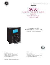
GE Multilin G650 Instruction Manual (218 pages)
Generator Protection & Control System
Brand:
GE
| Category:
Control Systems
| Size: 4.63 MB
Table of Contents
Table of Contents
3
Getting Started
7
Important Procedures
7
Cautions and Warnings
7
Inspection Checklist
10
Safety Instructions
12
Overview
13
Introduction to 650 Family of Relays
13
Hardware Architecture
13
Software Architecture
15
Communications Architecture
15
Enervista 650 Setup Software
17
System Requirements
17
Installation
17
Connecting Enervista 650 Setup with G650
21
Hardware
23
Mounting & Wiring
23
Communications
23
Faceplate Display
24
Maintenance
24
Product Description
27
Overview
27
G650 Overview
27
Summary
29
Ansi Device Numbers and Functions
29
Other Device Functions
30
Ordering Code
31
Technical Specifications
33
Protection Elements
33
Control
43
Monitoring
48
User-Programmable Elements
50
Metering
51
Inputs
52
Real Time Clock
54
Outputs
54
Control Power Supply
55
Communications
55
Optic Features
57
Environmental Characteristics
58
Packaging and Weight
58
Type Tests
58
Approvals
58
External Connections
59
Human Interfaces
61
Introduction
61
Values
61
Enervista 650 Setup Software Overview
61
Main Screen
63
Communication Menu
64
File Management
66
Enervista 650 Setup Menu Structure
70
File Menu Overview
71
Setpoint Menu Overview
75
Actual Values Menu Overview
83
Operations Menu Overview
86
Communication Menu Overview
87
Security Menu Overview
90
View Menu Overview
90
Help Menu Overview
90
Human Machine Interface (Hmi)
91
Display
91
Front Led Indicators
92
Pushbuttons
92
Front Port and Cover Sealing System
93
Text Menus
94
Graphic Display
112
Web Server 3.3.1 Home
121
Snapshot Events
122
Control Events
123
Alarms
124
Oscillography
125
Fault Report
126
Data Logger
127
Metering
128
Security
129
Adding Users
129
User Rights
129
Changing Passwords
130
Enabling Security
131
Loging into Enervista 650 Setup
132
Bootcode and
133
Introduction
133
Communication Parameters
134
Boot Code Upgrade
137
Firmware Version Upgrade
141
Firmware Upgrade
141
Boot Code Upgrade (*)
143
Firmware Upgrade (*)
144
Commissioning
145
Visual Inspection
145
General Considerations on the Power Supply Network
146
Isolation Tests
147
Indicators
148
Power Supply Testing
149
Communications
150
Verification of Measurement
151
Voltages
151
Phase Currents
151
Active, Reactive Power, and Cosj Metering
152
Frequency
152
Inputs and Outputs
153
Digital Inputs
153
Contact Outputs
154
Circuit Continuity Supervision Inputs
154
Latching Circuits
154
Connections for Testing Protection Elements
155
Instantaneous Overcurrent (50Ph, 50N, 50G y 50Sg)
156
Time Overcurrent (51Ph, 51Pl, 51N, 51G)
157
Directional Elements (67N, 67G)
158
Element
158
Undervoltage Elements (27P, 27X)
160
Element
160
Overvoltage Elements (59P, 59X, 59Nh)
161
Element
161
59Nh Element
162
Element - Neg Seq Ov
163
Frequency Elements (81O/81U)
164
Frequently Asked
165
Communications
165
Protection
167
Control and Hmi
168
Relay Configuration
169
Symptoms and Recommended Actions
171
Factory Default Settings
187
Factory Default Configuration
207
Ge Multilin Warranty
217
Advertisement
Related Products
GE Multilin GEK-113328A
GE Multilin MM300
GE Multilin DGT Series
GE Multilin g60
GE G60 UR Series
GE G6S28TSLSS
GE DuraDrum GTDX200EM
GE GLD5606VWW
GE GTK18ICDBS
GE Disposall GFC1020V
GE Categories
Refrigerator
Ranges
Microwave Oven
Air Conditioner
Dishwasher
More GE Manuals
Login
Sign In
OR
Sign in with Facebook
Sign in with Google
Upload manual
Upload from disk
Upload from URL