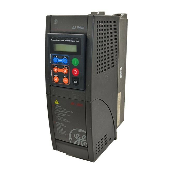
Sign In
Upload
Manuals
Brands
GE Manuals
Controller
AV-300i
GE AV-300i Manuals
Manuals and User Guides for GE AV-300i. We have
3
GE AV-300i manuals available for free PDF download: User Manual, Quick Start Up Manual
GE AV-300i User Manual (296 pages)
Brand:
GE
| Category:
DC Drives
| Size: 1.82 MB
Table of Contents
Safety Symbol Legend / Légende des Signes de Sécurité
4
Table of Contents
5
Chapter 0 - Safety Precautions / Precautions de Securit
13
Chapter 1 - Function Description
17
General Considerations
17
Variable Connection Methods
18
Block Functions
19
Signal Normalization
22
Drive Status Menu (STATUS)
25
Status
25
State of the Digital Inputs/Outputs (I/O Status)
25
Drive Advanced States (Advanced Status)
26
Driveid States (Drive ID Status)
27
Alarm Register (Alarm Log)
27
Drive Initialization (STARTUP - Setup Mode)
28
Selection of the Regulation Mode (Regulation Mode)
28
Drive Starting Configurations (Startup Config)
29
Setup Mode (Enter Setup Mode)
29
Encoder Configuration (Encoders Config)
31
Loading of the Setup Settings (Load Setup)
31
Speed Scale (Full Scale Speed)
31
Index Storing Function
33
Constant V/F " Control (V/F Config)
35
Speedregulation Gain Calc Control (Spdreg Gain Calc)
35
Control of the Motor Overload (Overload Contr)
36
I 2 T Protection against a Drive Overload
36
Motor Thermal Protection (Motor Protection)
37
Braking Unit Protection (BU Protection)
38
Enabling of the Internal Braking (ENABLE BU)
38
Figure 1.3.2.8.1: Braking Unit Function
38
In General
39
Recipes - Import Recipe & Export Recipe
39
Table 1.3.3.1: Recipe "Appl Function
40
Table 1.3.3.2: Recipe "Ramp & Speed Config
41
Table 1.3.3.3: Recipe "Appl Card & Comm
42
Table 1.3.3.4: Recipe"I/O Config
43
Parameter Settings on the Regulators (REGULATION PARAM)
45
Regulators
45
Dead Time Comp
46
Function and Parameterization of the V/F Control (V/F Reg Param)
47
V/F Regulation Control (V/F Control)
47
Energy Saving (V/F Save Energy)
48
V/F Catch on Fly from Running on AC Input
49
Automatic Restart after a Temporary Alarm: Retrying
50
Catch on the Fly Process
50
Gain Profiling Speed Feedback in a Sensorless Mode (Sls Spdfbk Gains)
50
Manual Tunings of Regulator Loops (Test Generator)
53
Test Generator Function
53
Manual Tuning of the Current Regulator
54
Figure 1.4.5.2.1: Output Current (Reaction Time @ 3Ms) Displaying
54
Manual Tuning of the Flux Regulator
55
Figure 1.4.5.2.2: Optimal Output Current (Reaction Time @ 1Ms) Displaying
55
Figure 1.4.5.3.1: Flux Reference (CH1) and Flux (CH2) Displaying
56
Figure 1.4.5.3.2: Flux Reference (CH1) and Tuning of Flux (CH2) Displaying
56
Manual Tuning of the Speed Regulator
57
Figure 1.4.5.3.3: Flux Reference (CH1) and Tuning of Magn Current Reference (CH2) Displaying
57
Figure 1.4.5.3.4: Flux Reference (CH1) and Magn Current Reference, with Overshoots, (CH2) Displaying
57
Figure 1.4.5.4.1: Speed Ref1 (CH1) and Norm Speed (CH2) Displaying
58
Figure 1.4.5.4.2: Speed Ref1(CH1) and Norm Speed (CH2), with Overshoot, Displaying
58
Command Configuration (I/O CONFIG)
59
Definition of the Commands
59
Command Block (Commands)
60
Enable/Disable Control Function
62
Typical Command Configurations
62
Control from Keyboard/Display Module (Factory Setting)
62
Control from Remote Pushbuttons
63
Table 1.5.3.1-1: Setup for Control from Keyboard (Factory Setup)
63
Table 1.5.3.2-1: Example Setup for Pushbutton Control
63
Control from a LAN, Usage of Fast Stop
64
Unmanned Installation
64
Table 1.5.3.3-1: Example Setup for LAN Control with Wired Fast Stop
64
Table 1.5.3.4-1: Example Setup for Unmanned Installation
65
Configuration of the Analog and Digital Inputs/Outputs (I/O CONFIG)
66
Analog Input Block (Analog Inputs)
66
Analog Input Block for 1X and 2X Expansion Cards (Exp Analog Inputs 1X & 2X)
69
Analog Output Block (Analog Outputs)
71
Digital Input Block (Digital Inputs)
72
Digital Output Block (Digital Outputs)
75
Configuration of the OK Relay (Terminals 80, 82)
77
Word Composing and Decomposing Block (Bits->Word & Word->Bits)
77
Forward and Reverse Control Block (Fwd Rev Ctrl)
81
Ramp Configuration (RAMP CONFIG)
83
Ramp Setpoint Block (Ramp Setpoint)
83
Multi Ramp Block (Multi Ramp)
85
Figure 1.7.2.1: Acceleration and Deceleration Ramps
87
Ramp Block (Ramp Function)
88
Figure 1.7.3.1: Ramp Shape
89
Speed Configurations (SPEED CONFIG)
90
Speed Setpoint Block and Speed Ratio Block (Speed Setpoint & Speed Ratio)
90
Example: Rubber Calender
92
Speed Regulation Block (Spd Reg Function)
93
Jog Function Block (Jog)
95
Multi Speed Block (Multi Speed)
97
Motopotentiometer Block (Moto Pot)
99
Speed Zero Control Block (Spd 0 Logic)
101
Speed Regulator Gain Profile Block (Speed Gain Profile)
103
Droop Block "Current Scale" (Speed Droop)
106
Speed Feedback Derivative Block "Speed Up" (Spd Fbk Deriv)
107
Inertia and Friction Compensation Block (Inertia / Frict Cp)
108
Torque Current Configurations (TORQUE CONFIG)
110
Block Generating the Torque Setpoint, the Torque Current Limit Control and the Zero Torque
110
(Torque Setpoint - Torque Curr Lim - Zero Torque CMD)
110
DC Link Voltage Control (Vdcctrl Reg - Max Regen Power)
114
Flux Current Configurations (FLUX CONFIG)
115
Control of the Flux Current Maximum Limit (Flux Max Limit)
115
Control of the Magnetizing Current (Magnetiz Config)
115
Output Voltage Control (Output Vlt Ref)
116
Stop Option Control (STOP OPTION)
118
Direct Current Braking Control - DC Braking
118
Power Loss Control (Power Loss Ctrl)
119
Power Loss Ridethru (Pwrloss Ridethru)
120
Power Loss Stop (Pwrloss Stop)
120
Figure 1.11.2.1: Power Loss Control Function
122
Figure 1.11.2.2: Power Loss Stop
123
Alarm Block Configurations (ALARM CONFIG)
124
Alarm State
124
Alarms
124
Alarm Configurations
125
Alarm List and Alarm Recognition
125
Alarm Log
125
Hold off Time
125
Activity
126
Regulation Alarm Reset
126
Restart
126
Restart Time
126
Alarm Status on a Digital Variable
129
Table 1.12.1: Alarm List
130
Fault Pin
131
Table 1.12.8.1: Fault Pin List
131
Serial Communications (COMMUNICATION)
132
Communication Via the RS485 Serial Port (RS485)
132
Communication Via the SBI Bus Field Card (SBI)
132
Communication Via the Isbus Card (Isbus)
134
Application Card Configuration (APPL CARD CONFIG)
138
Configuration of the DGFC Option Card (DGFC)
138
PID Control (Appl Function)
141
Feed Forward Signal - PID Feed-Forward
142
PID Control Enabling (Pid Function)
142
PID Input Block (PID Input)
143
Dynamic Clamp Function
145
Integer Proportional Control (PI Control)
145
Gain Increase at the Starting
149
PI Clamp Top and Bottom Setting
149
Proportional Derivative Control (PD Control)
149
Setting of the Starting Diameter
149
PID Output Block (PID Output)
151
Diameter Calculation (Diameter Calc)
152
Dancer Constant Measurement
153
Figure 1.15.7.1: Diameter Calculation
153
Procedure for the Calculation of the Starting Diameter
154
Applications Examples for the PID Function
155
Control of Nip Rolls with Dancer
155
Figure 1.16.1.1: Control of Nip Rolls with Dancer
155
Input/Output
155
Machine Data
155
Parameters
156
Control of Nip Rolls with Loading Cell
157
Figure 1.16.2.1: Control of Nip Rolls with Loading Cell
157
Input/Output
158
Machine Data
158
Parameters
158
Control of Winders/Unwinders with Dancer
160
Figura 1.16.3.1: Control of Winders/Unwinders with Dancer
160
Input/Output
160
Machine Data
160
Parameters
161
Figure 1.16.4.1: Outlining of the Dancer Constant Measurement
163
Parameters Referring to the Function for the Calculation of the Starting Diameter
163
Figure 1.16.5.1: Winder/Unwinder Control with Diameter Sensor
164
Use of the Diameter Sensor
164
Figure 1.16.5.2: Relationship between the Transducer Signal and the Winder Diameter
165
Figure 1.16.6.1: Pressure Control for Pumps and Extruders
166
Input/Output
166
Machine Data
166
Pressure Control for Pumps and Extruders
166
Parameters
167
Generic PID
168
Parameters
168
Application Note: Dynamic Change of the PI Block Integral Gain
169
Figure 1.16.8.1: Example with a Small and Big Diameter
169
Figure 1.16.8.2: PI I Gain PID and PI I Output PID Ratio
170
Customer Functions (CUSTOM FUNCTIONS)
171
Signal Comparator (Compare)
171
Use Variables (Pad Parameters)
173
Chapter 2 - Block Diagrams
175
Status V/F
175
Status Field Oriented Control
176
Status Sensorless
177
V/F Control
178
Field Oriented Control
179
Sensorless Vector Control
180
Inertia Compensation
180
Droop
180
Speed Feedback Derivative
183
Speed Regulator
184
Speed/Torque Control
185
Speed Reference Generation
186
Multi Speed
187
Motor Potentiometer
188
Ramp Setpoint
189
Multiramp
190
Ramp
191
Jog
192
Speed Setpoint
193
Motor Control
194
Speed Feedback
195
Spd Gain Profile
196
Power Loss Stop / Ride through Control
197
Commands
198
DC Braking
199
Speed Zero Block
200
Custom Functions
201
Input/Output, Appl Card Config, Communication, Fwd-Rev Control
202
Terminal Board Layout Drawing
203
Input-Output: Aninp 1
204
Input-Output: Aninp 2
205
Input-Output: Aninp 3
206
Input- Aninp 1-2X
207
Input Output - Standard Analog Outputs
208
Input Output - Expansion Analog Outputs
209
Input Output - Standard Digital Outputs
210
Input Output - Expansion Digital Outputs
211
Input Output - Standard + Expansion Digital Outputs
212
Bit to Word
213
Word to Bit
214
Isbus Configuration
215
Sbi Configuration
216
Dgfc Fast (Sync) Channels Configuration
217
Dgfc Slow (Sync) Channels Configuration
218
Forward Reverse Control Block
219
PID Function
220
PID Function - Input
221
PID Function - Feed Forward
222
PID Function - Int Diameter Setting
223
PID Function - Intitial Diameter Calculation
224
PID Function - Pipart
225
PID Function - Pigain Scheduler
226
PID Function - Pdpart
227
PID Function - Pd Gain Scheduler
228
PID Function - Output
229
Overload Settings
230
Chapter 3 - Parameters & Pick Lists
231
Menu with Parameter Numbers
231
Menu Legend
231
Menu
232
Setup Mode Menu
252
Pick Lists
253
Pick List 1
253
Pick List 2
253
Pick List 3
254
Pick List 4
254
Pick List 5
254
Pick List 6
255
Pick List 7
255
Pick List 10
256
Pick List 8
256
Pick List 9
256
Pick List 11
257
Pick List 12
257
Pick List 13
257
Pick List 14
258
Pick List 15
258
Pick List 16
258
Pick List 17
258
Pick List 18
259
Pick List 19
259
Pick List 20
260
Pick List 21
260
Pick List 22
260
Pick List 23
260
Pick List 24
261
Pick List 25
261
Pick List 26
261
Pick List 27
262
Pick List 28
262
Pick List 29
263
Pick List 30
263
Pick List 31
264
Pick List 32
264
Pick List 33
265
Pick List 34
265
Pick List 35
266
Pick List 36
266
Pick List 37
266
Pick List 38
267
Pick List 39
267
Pick List 40
267
Pick List 42
268
Pick List 43
268
Pick List 44
269
Pick List 45
269
Numeric Order Parameters List
270
Numeric Order Parameter List Caption
270
Numeric Order Parameter List
272
Warranty Parts and Service
294
Advertisement
GE AV-300i Quick Start Up Manual (30 pages)
Industrial Systems
Brand:
GE
| Category:
Controller
| Size: 0.82 MB
Table of Contents
Table of Contents
3
1 Safety Precautions - Precautions de Securité
4
Functional Connection Diagram
7
2 Overview
8
3 Control Terminals
9
Maximum Cable Cross Section for Regulator Terminals
10
4 Power Terminals
10
Maximum Cable Cross Section for Power Terminals
10
5 Encoder Terminals (XE Connector)
11
Encoder Type Connection
11
JUMPERS Setting
12
List of Jumpers and Dip-Switch
12
List of Dip-Switch
13
Maximum Cable Length for Encoder Terminals
13
6 Keypad Operation
14
Keypads (on Right the Optional LED Module)
14
Leds
14
Moving Inside a Menu
16
7 Pre Power Checks
17
8 Quick Tuning
18
9 Options
22
10 Quick Tuning Guide for Factory Configured Drives
22
11 Troubleshooting
23
Overflow List
23
List of Self-Tuning Errpr Messages
24
Failure Alarms in the Keypad Display
25
Other Faults
27
GE AV-300i User Manual (20 pages)
Brand:
GE
| Category:
Control Unit
| Size: 0.13 MB
Table of Contents
Safety Symbol Legend
3
Table of Contents
4
Chapter 0 - Safety Precautions / Precautions de Securité
13
Chapter 1 - Function and Features (Overview)
17
Upon Delivery Inspection Procedures
19
Inverter Type Designation
19
Chapter 2 - Inspection Procedure, Component Identification and Standard Specification
19
Advertisement
Advertisement
Related Products
GE AF-600
GE AF-60 LP
GE AF-300 P11
GE ASTAT Plus
GE ASTAT XL Series
GE ASTAT XB
GE ASTAT XBm
GE ACT17CWA
GE ASTAT XL
GE AVS06
GE Categories
Refrigerator
Ranges
Microwave Oven
Air Conditioner
Dishwasher
More GE Manuals
Login
Sign In
OR
Sign in with Facebook
Sign in with Google
Upload manual
Upload from disk
Upload from URL