Sign In
Upload
Manuals
Brands
Flowserve Manuals
Valve Positioners
Logix 520MD+
Flowserve Logix 520MD+ Manuals
Manuals and User Guides for Flowserve Logix 520MD+. We have
2
Flowserve Logix 520MD+ manuals available for free PDF download: User Instructions
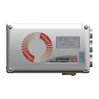
Flowserve Logix 520MD+ User Instructions (84 pages)
Digital Positioners
Brand:
Flowserve
| Category:
Valve Positioners
| Size: 1.93 MB
Table of Contents
Table of Contents
2
1 General Information
5
Using this Document
5
Terms Concerning Safety
5
Protective Clothing
5
Qualified Personnel
5
Valve and Actuator Variations
5
Spare Parts
5
Logix ® 520MD+ and 510+ Digital Positioners FCD LGENIM0105-15-AQ
5
Service / Repair
6
Disposal
6
Basic Operation
6
Hart
6
Position Definition
6
Command Input and Final Command
7
Outer Loop
7
Inner Loop
7
Figure 1: Principles of Operation of Logix 500
7
Detailed Sequence of Positioner Operations
8
Inner Loop Offset
8
Figure 2: Principles of Operation of Logix 500
8
Figure 3: Logix 500+ Digital Positioner Schematic
9
2 Specifications
10
Input Signal
10
Pneumatic Output
10
Air Supply
10
Analog Output - Multi-Function Card
10
Stroke Output
11
Remote Mount Specifications
11
Limit Switch Specifications
11
To I Board Specifications
11
Positioner Performance Characteristics
11
Physical Specifications
11
Temperature
11
Valvesight DTM Software Specifications
12
3 Hazardous Area Certifications
13
4 Storage and Unpacking
14
Storage
14
Unpacking
14
Pre-Installation Inspection
14
Labels
14
Figure 4: Certification Label
14
Figure 5: Model Code Label
14
5 Mounting and Installing
15
Mounting to Mark One Linear Valves
15
Figure 6: Mounting to Mark I Linear Valves
15
Mounting to Flowtop Linear Valves
16
Figure 7: Flowtop Mounting Bracket
16
Logix ® 520MD+ and 510+ Digital Positioners FCD LGENIM0105-15-AQ
16
Figure 8: Flowtop Mounting
17
Mounting to Standard Valtek Rotary Valves
18
Figure 9: Valtek Rotary Follower Arm
18
Figure 10: Valtek Rotary Take-Off Arm
18
Figure 11: Valtek Rotary Mounting
18
Figure 12: Valtek Rotary Final Orientation
19
Mounting to Maxflo Rotary Valves
20
Figure 13: Maxflo Take-Off Arm
20
Figure 14: Maxflo Follower Arm
20
Figure 15: Maxflo Assembly
20
Figure 16: Maxflo Connection
20
Mounting to Rotary Namur (Automax) Valves
21
Figure 17: Automax Bracket
22
Figure 18: Automax Assembly
22
Mounting to a Linear Namur Pneumatic Actuator
23
Figure 19: Mounting to a Linear Actuator
23
6 Tubing
24
Determine Air Action
24
Figure 20: Linear, Double Acting, Air to Open
24
Figure 21: Rotary, Double Acting, Air to Open
24
Connect Supply Port
25
Purging Single Acting Actuators
25
Vented Design
25
Figure 22: Linear, Single Acting, Air to Open
25
Figure 23: Exhaust Vents
25
Figure 24: Pneumatic Connections
26
7 Electrical Connections
27
Electrical Terminals
27
Command Input (4-20 Ma) Connection
27
Figure 25: Terminal Diagram
27
Figure 26: Compliance Voltage
28
Multi-Function Card (AO, DO, DI)
29
Figure 27: Conduit and Grounding
29
Figure 28: MFC Analog Output Circuit
29
Figure 29: MFC Discrete Output Circuit
30
Figure 30: MFC Discrete Input Circuit
30
To I Card Connections
31
Figure 32: V to I Card Circuit
31
Figure 33: V to I Card Installed
31
Limit Switches
32
Figure 34: Limit Switch Board
32
Remote Mount
33
Connections for Intrinsically Safe Operation
33
Figure 35: Remote Mount Board
33
8 Startup
34
Quick Start Instructions
34
Local User Interface Overview
34
Figure 36: Local User Interface
34
Configuration Switch Settings
35
Stroke Calibration
36
Figure 37: Selectable Gain Switch
36
Analog Output (AO) Calibration
37
9 Positioner Functions (no Display Required)
38
Live Manual Tuning (Adjusting the Gain)
38
Local Control of Valve Position
38
Command Source Reset
38
Factory Reset
38
Viewing Version Numbers
38
Analog Input Calibration
39
Select and Calibrate Analog Output
39
Select Discrete Output
39
10 Positioner Functions (LCD Display)
40
Main Display View
40
Figure 38: Display Main View
41
Menu Overview
42
Menu Features
43
Figure 39: Characterization Curves
46
11 Hart Communication
49
Valvesight DTM
49
Hart 375/475 Handheld Communicator
49
Changing Hart Versions
49
Figure 40: Valvesight DTM Dashboard
49
Burst Mode
50
Figure 41: Hart Dip Switch
50
12 Model Features
51
MD+ Positioner Diagnostic Levels
51
Valvesight DTM Diagnostic Levels
51
13 Multi-Function Card
52
Analog Output (AO)
52
Discrete Output (DO)
52
Discrete Input (DI)
52
Figure 42: Multi-Function Card
52
14 To I Card
53
15 Limit Switches
53
Limit Switch Operation
53
Limit Switch Types
53
Figure 31: V to I Card
53
Figure 43: V to I Card
53
16 Remote Mount
54
Remote Mount Operation
54
Figure 44: Limit Switches
54
Figure 45: Remote Mount Board
54
17 Requirements for Safety Integrity
55
Fail Safe State
55
Safety Function
55
Fail Safe State Response Time
55
Positioner Model Selection and Specification
55
Installation
55
Required Configuration Settings
55
Maximum Achievable SIL
55
Reliability Data
55
Lifetime Limits
56
Proof Testing
56
Maintenance
56
Repair and Replacement
56
Training Requirements
56
18 Maintenance and Repair
57
Scheduled Maintenance
57
Required Tools and Equipment
57
Torque Specification for Screws
57
Installing a Limit Switch
57
Figure 46: Tools for Positioner Maintenance
57
Figure 47: Limit Switch
58
Replacing the LCD Board
59
Replacing an Auxiliary Card
59
Figure 48: Inner Cover
59
Figure 49: LCD
59
Figure 50: Auxiliary Card
60
Replacing a Main Board
61
Replacing the Pressure Sensor Board
61
Figure 51: Main Board Screws
61
Figure 52: Main Board Connectors
61
Figure 53: Pressure Sensor Board
61
Cleaning and Replacing a Double Acting Pilot Relay
62
Figure 54: Inserting the Double Acting Block Assembly
62
Replacing a Single Acting Pilot Relay
63
Figure 55: Double Acting Relay Assembly
63
Figure 56: Clip Spring Orientation
63
Figure 57: Single Acting Relay Assembly
64
19 Troubleshooting
65
Troubleshooting Guide
65
Status Code Index
67
Status Code Descriptions
67
Help from Flowserve
76
20 Positioner Dimensions
77
21 How to Order
78
Positioners
78
Spare Parts Kits
80
Figure 58: Spare Parts Kits
80
Gage Blocks
81
VDI/VDE 3847 Mounting Blocks
82
Mounting Kits
82
Advertisement
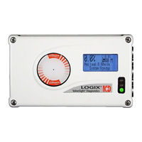
Flowserve Logix 520MD+ User Instructions (56 pages)
Digital Positioner
Brand:
Flowserve
| Category:
Valve Positioners
| Size: 8.95 MB
Table of Contents
Table of Contents
2
Contents
3
General Information
3
Using this Document
3
Terms Concerning Safety
3
Protective Clothing
3
Qualified Personnel
3
Valve and Actuator Variations
3
Valve and Actuator Installation
3
Spare Parts
3
Service / Repair
3
Principles of Operation
5
Basic Operation
5
Hart
5
Position Definition
5
Command Input and Final Command
5
Outer Loop
5
Inner Loop
6
Detailed Sequence of Positioner
6
Inner Loop Offset
6
Operations
6
Specifications
7
Input Signal
7
Air Supply
7
Pneumatic Output
7
Stroke Output
7
Analog Output
7
Safety Discrete Output
7
Temperature
7
Positioner Performancec
8
Physical Specifications
8
Limit Switch Specifications
8
Valve Sight Dtm Softwares
8
Haracteristics
8
Pecifications
8
Storage and Unpacking
9
Storage
9
Unpacking
9
Pre-Installation Inspection
9
Mounting and Installation
10
Mounting to Mark One Linearv
10
Alves
10
Mounting Positioner to Flow-Top
11
Flow-Top Linear Valve
11
Mounting Positioner to Standard
12
Valtek Rotary Valves
12
Mounting Positioner to Namur R
13
Otary Valves
13
Tubing
14
Determine Air Action
14
Connect Supply Port
14
Purging Single Acting Actuators
14
Vented Design
14
Pneumatic Terminals
15
Electrical Connections
16
Electrical Terminals
16
Command Input (4-20 M A) C
16
Compliance Voltage
16
Onnection
16
Cable Requirements
17
Grounding and Conduit
17
Electromagnetic Compatibility
18
Intrinsically Safe Barriers
18
Multi -Function Card
18
(Ao, Do, DI)
18
Safety Discrete Output (Safety Do)
19
Limit Switches
19
8 Startup
20
Startup
20
Quick Start Instructions
20
Local User Interface Overview
20
Configuration Switch Settings
20
Stroke Calibration
21
Positioner Functions (no Display Required)
23
Live Manual Tuning (Adjusting the Gain)
23
Local Control of Valve Position
23
Command Source Reset
23
Factory Reset
23
Viewing Version Numbers
23
Positioner Functions (Lcd Display)
24
Main Display View
24
Menu Overview
26
Menu Features
27
Hart Communication
32
Valvesight Dtm
32
Hart 375/475 Handheld Communicator
32
Burst Mode
32
Change from Hart
32
Hart 5
32
Diagnostic Features
33
Positioner Diagnostic Levels
33
Dtm Diagnostic Levels
33
Limit Switches
34
Limit Switch Principles of Operation
34
Limit Switch Types
34
Multi-Function Card
35
Analog Output (Ao)
35
Discrete Output (Do)
35
Discrete Input (DI)
35
Safety Do Card
36
Safety Do Function
36
Maintenance and Repair
37
Scheduled Maintainance
37
Installing a Limit Switch
37
Replacing the Lcd Board
38
Replacing an Auxiliary Card
38
Replacing a Main Board
39
Replacing the Pressure Sensor Board
39
Replacing a Double Acting Pilot Relay
39
Replacing a Single Acting Pilot Relay
40
Troubleshooting
41
Troubleshooting Guide
41
Status Code Index
42
Status Code Descriptions
43
Positioner Dimentions
50
Positioner Dimensions
50
Positioner Dimensions with Options
51
How to Order
52
Positioners
52
Spare Parts Kits
54
Mounting Kits
54
Advertisement
Related Products
Flowserve Logix 520si Series
Flowserve Logix 520MD Series
Flowserve Logix 510+
Flowserve Logix 3200MD Plus
Flowserve Logix 3400MD
Flowserve Logix 3200MD
Flowserve Logix 3200IQ
Flowserve Logix 3000MD Series
Flowserve Logix 500 Series
Flowserve Logix 520 Series
Flowserve Categories
Control Unit
Controller
Water Pump
Valve Positioners
Racks & Stands
More Flowserve Manuals
Login
Sign In
OR
Sign in with Facebook
Sign in with Google
Upload manual
Upload from disk
Upload from URL