Sign In
Upload
Manuals
Brands
Emerson Manuals
Measuring Instruments
SIS
Emerson SIS Manuals
Manuals and User Guides for Emerson SIS. We have
1
Emerson SIS manual available for free PDF download: Reference Manual
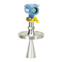
Emerson SIS Reference Manual (226 pages)
Level Transmitters. Non-Contacting Radar
Brand:
Emerson
| Category:
Measuring Instruments
| Size: 28.71 MB
Table of Contents
Table of Contents
3
Using this Manual
13
Product Recycling/Disposal
13
2Section 2: Transmitter Overview
13
Measurement Principle
15
Process Characteristics
16
Dielectric Constant
16
Foam and Turbulence
16
Condensation
17
Dust
17
Solid Surface
17
Vessel Characteristics
18
In-Tank Obstructions
18
Tank Shape
18
Application Examples
18
Components of the Transmitter
21
System Integration
22
Safety Messages
23
Confirm Approval Type
24
Review Mounting Considerations
24
Mounting Position
24
Free Space Requirements
25
Antenna Size
26
Antenna Inclination
26
Non-Metallic Tanks
26
Beam Width and Beam Angle
27
Nozzle Requirements
28
Still Pipe/Chamber Installations
31
Ball Valve Installation
32
Review Mounting Preparations
33
Assemble the Segmented Cone Antenna
33
Shorten the Extended Cone Antenna
35
Mount the Cone Antenna
36
Flanged Version
37
Flanged Version with Air Purge Ring (Option Code PC1)
38
Threaded Version
40
Bracket Mounting
46
Align Transmitter Head
49
Mount the Process Seal Antenna
51
Flanged Version
51
Tri Clamp Version
53
Mount the Parabolic Antenna
54
Flanged Version
55
Threaded Version
56
Welded Version
60
Adjust the Inclination of the Antenna
65
Connect the Air Purging
68
Adjust Display Orientation (Optional)
69
Safety Messages
71
Cable Selection
72
Cable Gland/Conduit
72
Power Supply
72
Hazardous Areas
72
Wiring Diagram
73
Grounding
74
Transmitter Housing
74
Signal Cable Shield Grounding
74
Wiring and Power up
75
Electrical Installation
76
Optional Devices
78
Rosemount ™ 333 HART Tri-Loop
78
Safety Messages
79
Overview
79
System Readiness
80
Confirm Correct Device Driver
80
Get Started with Your Preferred Configuration Tool
80
Rosemount Radar Master Plus
80
AMS Device Manager
81
Field Communicator
82
Confirm HART Revision Capability
82
Switch HART Revision Mode
82
Configure Device Using Guided Setup
83
Verify Level
84
Establish Multidrop Communication
85
Use with the Rosemount 333 HART Tri-Loop
86
LCD Display Screen Messages
87
Startup Screen Sequence
87
Variable Screens
88
Set up the LCD Display
88
View Measurement Data
89
View Current Measurement Values
89
Interpret Measurement Status
90
Check Device Status
90
Safety Messages
93
Diagnostic Messages
94
Troubleshooting Guide
99
Service and Troubleshooting Tools
104
Use the Echo Curve
104
Manage Disturbance Echoes
107
Perform an Analog Loop Test
112
Use the TEST Terminal
113
Calibrate Analog out
114
Save and Load Configuration Files
115
Restore to Default Settings
115
Use the Simulation Mode
116
View Input Registers
116
10View/Edit Holding Registers
116
Write Protect a Transmitter
117
Application Challenges
118
Handling Disturbances at Top of Tank
118
Tracking of Weak Surface Echoes Close to Tank Bottom
120
Handling Ghost Echoes in Still Pipes
122
Handling Strong Double Bounce Echoes
123
Transmitter Head Replacement
124
Cleaning or Replacing the PTFE Sealing
127
Remove from Service
127
Cleaning
127
Replacing
127
Service Support
131
Safety Messages
133
Terms and Definitions
134
Safety Instrumented Systems
134
Safety Instrumented System (SIS) Certification
136
Safety Certified Identification
137
Installation
138
Measuring Range
138
Configuration
138
Prerequisites
138
Configure Device Using Guided Setup
138
Set Operational Mode
138
Enable Safety Mode
139
Alarm and Saturation Levels
140
Site Acceptance
140
Proof-Testing
140
Overview
140
Tools Required
141
1-Point Level and Analog Output Verification
142
2-Point Level and Analog Output Verification
143
Analog Output Verification
144
Level Deviation Monitoring
145
Product Repair
145
Specifications
145
Performance Specifications
147
General
147
Measuring Range
147
Environment
149
Functional Specifications
149
General
149
Display and Configuration
149
4-20 Ma HART
150
Diagnostics
151
Process Temperature and Pressure Rating
152
Temperature Limits
153
Flange Rating
153
Conditions Used for Flange Strength Calculations
153
Air Purging
153
A.2.10System Integration
154
Physical Specifications
154
Material Selection
154
Engineered Solutions
154
Housing and Enclosure
154
Tank Connection
155
Flange Dimensions
155
Antenna Versions
155
Material Exposed to Tank Atmosphere
155
Ordering Information
156
Spare Parts and Accessories
167
Dimensional Drawings
175
Standard Flanges
179
European Directive Information
181
Safety Instrumented Systems (SIS)
181
Telecommunication Compliance
181
Fcc
181
Radio Equipment Directive (RED) 2014/53/EU
182
Installing Equipment in North America
182
U.s.a
182
Canada
184
B.10Europe
186
Europe
186
B.11International
188
International
188
B.12Brazil
189
B.13China
189
Brazil
189
China
189
B.14Republic of Korea
190
B.15Additional Certifications
190
B.16Installation Drawings
190
Republic of Korea
190
Additional Certifications
190
Installation Drawings
190
Menu Tree
197
Device Setup
199
HART ® Protocol
199
Units
199
Analog Output
199
Display
200
Security
201
Device Information
201
Level Setup
201
Geometry
201
Environment
208
Volume
208
Scaled Variable
209
Antenna
210
Advanced
211
Alert Setup
215
Measurement Recovery
215
Signal Quality Alert
215
High/Low User Defined Alert
216
Advertisement
Advertisement
Related Products
Emerson R&S SGT100A
Emerson Site Manager
Emerson SI-Universal
Emerson SI-PROFIBUS
Emerson SI-DeviceNet
Emerson SI-I/O
Emerson SI-EtherCAT
Emerson Site Supervisor
Emerson SPMC2402
Emerson Fisher Vee-Ball SS-84PSV4
Emerson Categories
Controller
Control Unit
Transmitter
Measuring Instruments
Fan
More Emerson Manuals
Login
Sign In
OR
Sign in with Facebook
Sign in with Google
Upload manual
Upload from disk
Upload from URL