Sign In
Upload
Manuals
Brands
Emerson Manuals
Computer Hardware
Pm8560
Emerson Pm8560 Manuals
Manuals and User Guides for Emerson Pm8560. We have
1
Emerson Pm8560 manual available for free PDF download: User Manual
Emerson Pm8560 User Manual (146 pages)
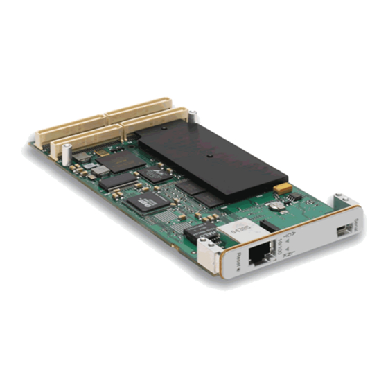
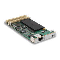
Octal E1/T1/J1 Line Interface PTMC
Brand:
Emerson
| Category:
Computer Hardware
| Size: 4 MB
Table of Contents
Table of Contents
5
1 Overview
15
Components and Features
15
Functional Overview
16
Figure 1-1: General System Block Diagram
17
Memeory Map
18
Functional Overview
18
Address Summary
19
Additional Information
20
Product Certification
20
Table 1-2: Regulatory Agency Compliance
20
Rohs Compliance
21
Terminology and Notation
21
Technical References
22
2 Setup
25
Electrostatic Discharge
25
Table 2-1: Circuit Board Dimensions
25
Pm8560 Circuit Board
26
Figure 2-2: Component Map, Bottom (Rev. 01)
27
Figure 2-3: LED and Switch Locations, Top
28
Connectors
29
Front Panel
29
Pm8560 Setup
30
Power Requirements
30
Environmental Considerations
30
Reset Methods
30
Table 2-2: Environmental Requirements
30
System JTAG Chain
31
Installation
32
Troubleshooting
33
Figure 2-6: Installing the Pm8560 on the Baseboard
33
Figure 2-7: Serial Number and Product ID on the Bottom Side
34
Technical Support
34
Product Repair
35
3 Central Processing Unit
37
Pm8560 CPU Features
37
MPC8560 Functions
38
Microprocessor Core (E500)
39
L1 Cache
39
L2 Cache
39
Interrupts and Exception Processing3-3
39
Machine State Register
39
Communications Processor Module
40
Timers
40
Interrupt Controller
40
Figure 3-1: CPM Interrupt Structure
40
External Interrupt Sources
41
Internal Interrupt Sources
41
Table 3-2: External Interrupt Sources
41
MPC8560 CPM Port Pin Assignment
42
Table 3-3: MPC8560 Port Pin Assignments
42
MPC8560 Peripheral Modules
45
Three-Speed Ethernet Controllers
45
Local Bus Controller
45
Chip-Select Generation
45
Processor Reset and Clocking Signals
46
MPC8560 Exception Handling
46
Table 3-4: MPC8560 Chip Selects
46
4 On-Card Memory
47
Soldered Flash
47
Serial Eeproms
48
Emerson Memory Map
48
Double Data Rate SDRAM
49
DDR SDRAM Programming
49
5 Serial I/O
51
Serial Ports
51
Serial Port Connector P17 and Cable5-1
51
Figure 5-1: Serial Cable Assembly (Emerson Part Number C00003555-XX)
52
Table 5-2: Serial Cable Wiring Assignments
52
Baud Rate Selection
53
Baud Rate Generator Configuration
53
6 TDM Interface
55
TDM Framer and Line Interface
55
Framer
55
Line Interface
55
Framer Analog Interfaces
56
Framer to MPC8560 Interface
56
Interface Options
56
Signal Definitions
58
Figure 6-1: Data Flow between Framer and MPC8560
58
Framer Waveform Shape
59
Framer Interrupt Mechanism
59
Rear Panel I/O Connector P14
60
Table 6-2: Connector P14 Pin Assignments
60
7 PCI Bus Interface
63
MPC8560 PCI Features
63
PCI Support
63
Figure 7-1: MPC8560 PCI Controller Block Diagram
63
MPC8560 PCI Memory Map
64
PCI Vendor and Device ID
64
Vital Product Data (VPD)
64
Table 7-1: Pm8560 Vital Product Data Format
64
Monitor Display
65
Accessing the Serial EEPROM VPD
66
PCI Configuration Registers
66
Power-On Reset Modes
67
Monarch Mode
67
Table 7-2: Power-On Reset Configuration
67
PCI Interrupts
68
PMC Connector Pin Assignments
68
Figure 7-2: PMC Interface Connectors (P11-P14)
68
Table 7-3: Interrupt Connections for Pm8560
68
Table 7-4: P11, P12, and P13 Connector Pin Assignments
69
PCI Bus Control Signals
70
8 Programmable Logic Device
73
PLD Register Summary
74
Product ID
74
Hardware Version
74
PLD Version
75
PLL Configuration
75
Hardware Configuration 1
76
Jumper Settings
77
Led
77
Reset Event
78
Reset Command
79
PCI Reset out Enable
80
PCI Status
80
Boot Device Failover Mechanism
81
Miscellaneous Control
83
CT Bus Status
84
Clock and Sync Registers
84
Figure 8-2: Clock and Sync Registers Diagram
85
Framer Clock Source
86
NETREF Control
86
MT9045 System Synchronizer Control
87
SYNC Source
88
Primary Clock Source
89
Secondary Clock Source
90
RCLK Source
91
TCLK Source
91
Serial Presence Detect (SPD) Registers
92
Row Column
92
CAS Latency Refresh
93
SDRAM Cycle Time for CAS Latency
93
Minimum Row Precharge Time
94
Minimum Row Delay between Activations
95
Minimum Row Delay between RAS-To-CAS Assertions
95
Minimum Active-To-Precharge
96
Minimum Auto-Refresh to Active/Auto
96
Refresh
96
Write Recovery Time
97
Delay
97
9 Ethernet Interfaces
99
Ethernet Transceiver
99
MDIO/MDC Signals
99
Ethernet Address
99
Ethernet Connector
100
Table 9-2: Ethernet Port Address Numbering
100
Table 9-3: Ethernet Port Pin Assignments
100
10 Development Mezzanine Card
101
DMC Circuit Board
101
Table 10-1: DMC Mechanical Specifications
101
Connectors
102
P1 Connector Pin Assignments
103
Figure 10-2: P1 PCB-To-PCB Connector
103
Table 10-2: DMC P1 Connector Pin Assignments
103
P2 EIA-232 Interface
105
P3 Jtag/Cop
105
Figure 10-3: DMC P2 USB Mini-B Connector
105
Figure 10-4: DMC P3 JTAG/COP Header
105
Table 10-3: DMC P2 Connector Pin Assignments
105
Table 10-4: DMC P3 JTAG/COP Header Pin Assignments
105
P4 JTAG Chain Header
106
Table 10-5: DMC P4 JTAG Header Pin Assignments
106
DMC Jumpers and Leds
107
Table 10-6: DMC Jumper Port Assignments
107
DMC Setup
108
Installing the DMC Card
108
Troubleshooting
109
Figure 10-7: DMC Location on Pm8560
109
Figure 10-8: Serial Number and Product ID on Bottom Side
110
Product Repair
110
Technical Support
110
11 Monitor
113
Command-Line Features
113
Basic Operation
114
Power-Up/Reset Sequence
114
Figure 11-1: Example Monitor Start-Up Display
114
POST Diagnostic Results
116
Monitor SDRAM Usage
116
Updating the Monitor
116
Table 11-1: Post Diagnostic Results-Bit Assignments
116
Table 11-2: Monitor Address Per Flash Size
117
Boot Redirect and Monitor Recovery (Watchdog)
118
Updating the Monitor Via TFTP
118
Resetting Environment Variables
119
Monitor Command Reference
119
Command Syntax
119
Command Help
120
Typographic Conventions
120
Boot Commands
120
Bootbus
120
Bootd
121
Bootm
121
Bootp
121
Bootv
121
Dhcp
122
Rarpboot
122
Tftpboot
122
Memory Commands
122
Cmp
122
Find
123
Flash Commands
125
Erase
125
Flinfo
125
Protect
126
I2C Commands
126
Icrc32
126
Iloop
126
IMD
127
Imd2
127
IMM
127
Imm2
127
Imw
127
Inm
127
Iprobe
128
Iprobe2
128
Environment Parameter Commands
128
Printenv
128
Saveenv
128
Setenv
128
Srom_Wp
129
Test Commands
129
Diags
129
Mtest
129
Test_Watchdog
129
Other Commands
130
Autoscr
130
Base
130
Bdinfo
130
Coninfo
130
Crc32
130
Date
130
Echo
131
Enumpci
131
Getmonver
131
Help
131
Iminfo
131
Loop
131
Memmap
132
Moninit
132
Mon2Init
132
Monrecovery
133
Pci
133
Ping
133
Reset
133
Run
134
Script
134
Showmac
134
Showpci
134
Sleep
134
Version
134
Watchdog
134
Environment Variables
135
Table 11-3: Standard Environment Variables
135
Troubleshooting
136
Table 11-4: Optional Environment Variables
136
Download Formats
137
Binary
137
Motorola S-Record
137
12 Glossary
139
Advertisement
Advertisement
Related Products
Emerson PACSystem RX3i
Emerson PMAC II
Emerson PMAC II Solo
Emerson Avocent PM 3000
Emerson AVENTICS PM1
Emerson PMX Series
Emerson PMX1A-ZB21-TF5-1
Emerson PMX1A-ZB21-TF7-1
Emerson PMX2A-ZB45-TF5-1
Emerson PMX2A-ZB38-TFM-1
Emerson Categories
Controller
Control Unit
Transmitter
Measuring Instruments
Fan
More Emerson Manuals
Login
Sign In
OR
Sign in with Facebook
Sign in with Google
Upload manual
Upload from disk
Upload from URL