Sign In
Upload
Manuals
Brands
Eaton Manuals
Relays
EMR-5000
Eaton EMR-5000 Manuals
Manuals and User Guides for Eaton EMR-5000. We have
1
Eaton EMR-5000 manual available for free PDF download: Installation, Operation And Maintenance Manual
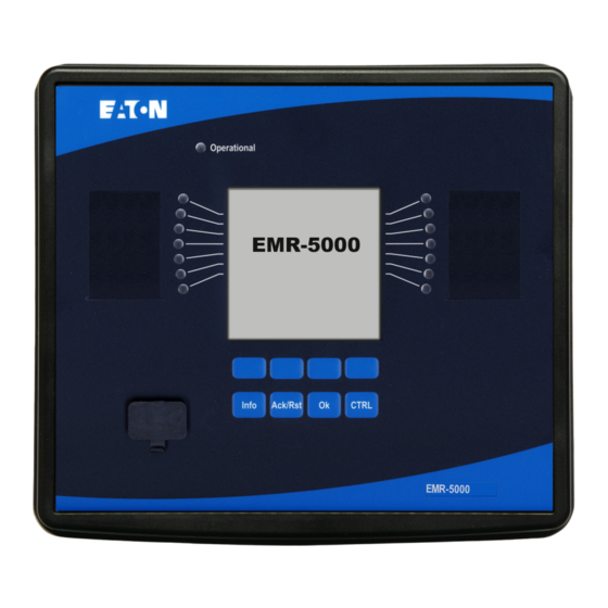
Eaton EMR-5000 Installation, Operation And Maintenance Manual (1060 pages)
MOTOR RELAY
Brand:
Eaton
| Category:
Relays
| Size: 26.14 MB
Table of Contents
EMR-5000 Functional Overview
2
Table of Contents
3
Comments on the Manual
9
What Is Included with the Device
14
Storage
14
Important Information
14
Symbols
15
General Conventions
21
Load Reference Arrow System
22
Device
23
Device Planning
23
Installation and Wiring
27
Three-Side-View
27
Overview of Slots - Assembly Groups
29
Slot X1: Power Supply Card with Digital Inputs
31
Slot X2: Relay Output Card - Zone Interlock
34
Slot X3: CT W1 - Current Transformer Measuring Inputs
37
Slot X4: CT W2 - Current Transformer Measuring Inputs
38
Slot X5: Multi Input - Output Card
49
Slot X6: Voltage Measuring Card
55
Slot X100: Ethernet Interface
61
Slot X103: Data Communication
63
Slot X104: IRIG-B00X and Supervision Contact
68
Slot X120 - PC Interface
70
Control Wiring Diagram
71
Wiring Diagrams
74
Input, Output and LED Settings
75
Digital Input Configuration
75
DI-8P X
76
DI-8 X Settings
80
Wired Inputs (Aliases)
84
Relay Output Configuration
88
RO-4ZI X - Settings
91
RO-4 X Settings
108
Analog Outputs
125
Analog Inputs
130
LED Configuration
145
The »System OK (Operational) « LED
148
LED Settings
149
Front Panel
166
Basic Menu Control
172
Powerport-E Keyboard Commands
173
Powerport-E
174
Installation of Powerport-E
175
Uninstalling Powerport-E
175
Setting up the Connection PC - Device
176
Restoring Device Data When Using Powerport-E
187
Loading of Device Data When Using Powerport-E
187
Backup and Documentation When Using Powerport-E
188
Printing of Device Data When Using Powerport-E (Setting List)
188
Off-Line Device Planning Via Powerport-E
190
Powerport-E Keyboard Commands
191
Measuring Values
192
Read out Measured Values
192
Differential Current - Measured Values
195
Current - Measured Values
197
Voltage - Measured Values
200
Power - Measured Values
204
Energy Counter
206
Global Parameters of the Energy Counter Module
206
Direct Commands of the Energy Counter Module
206
Signals of the Energy Counter Module (States of the Outputs)
206
Statistics
208
Configuration of the Minimum and Maximum Values
208
Configuration of the Average Value Calculation
209
Direct Commands
211
Global Protection Parameters of the Statistics Module
211
States of the Inputs of the Statistics Module
214
Signals of the Statistics Module
215
Counters of the Module Statistics
215
System Alarms
225
Demand Management
225
Peak Demand
228
Min. and Max. Values
228
THD Protection
228
Device Planning Parameters of the Demand Management
229
Signals of the Demand Management (States of the Outputs)
229
Global Protection Parameter of the Demand Management
230
States of the Inputs of the Demand Management
234
Resets
235
Manual Acknowledgment
237
Manual Acknowledgment Via Powerport-E
237
External Acknowledgments
238
External Acknowledge Via Powerport-E
238
External LED - Acknowledgment Signals
239
Manual Resets
249
Manual Resets Via Powerport-E
249
Reset to Factory Defaults
249
Status Display
250
Status Display Via Powerport E
250
Operating Panel (HMI)
251
Special Parameters of the Panel
251
Direct Commands of the Panel
251
Global Protection Parameters of the Panel
251
Recorders
252
Waveform Recorder
252
Fault Recorder
263
Event Recorder
272
Trend Recorder
276
Motor Start Recorder
283
Statistic Recorder
289
History Function
290
Time Synchronization
291
Accuracy of Time Synchronization
292
Sntp
299
Irig-B00X
307
Device Parameters
312
Date and Time
312
Version
312
Version Via Powerport-E
312
TCP/IP Settings
313
Direct Commands of the System Module
314
Global Protection Parameters of the System
316
System Module Input States
318
System Module Signals
319
Special Values of the System Module
320
Communication Protocols
321
Modbus
321
Iec 61850
328
Parameters
343
Parameter Definitions
343
Access Authorizations (Access Areas)
358
Passwords - Areas
358
How to Find out What Access Areas/Levels Are Unlocked
362
Unlocking Access Areas
362
Changing Passwords
363
Adaptive Parameters Via HMI
364
Access Authorizations (Access Areas)
367
Passwords - Areas
367
How to Find out What Access Areas/Levels Are Unlocked
371
Unlocking Access Areas
372
Changing Passwords
372
Changing Passwords Via Power-Port-E
373
Password Entry at the Panel
373
Password Forgotten
373
Parameter Setting at the HMI
374
Parameter Setting Via Power-Port-E
378
Setting Groups
381
Comparing Parameter Files Via Powerport-E
394
Converting Parameter Files Via Powerport-E
395
Program Mode
396
System Parameters
397
General System Parameters
397
System Parameters - Current Related
398
System Parameters - Voltage Related
399
System Parameters of the Ground Differential
400
Blocking
401
Permanent Blocking
401
Temporary Blocking
401
To Activate or Deactivate the Tripping Command of a Protection Module
403
Activate, Deactivate Respectively to Block Temporary Protection Functions
404
Protection (Prot) Module
406
How to Block All Protective and Supervisory Functions
406
Direct Commands of the Protection Module
413
Global Protection Parameters of the Protection Module
413
Protection Module Input States
414
Protection Module Signals (Output States)
414
Values of the Protection Module
415
Switchgear/Breaker - Manager
416
Single Line Diagram
417
Switchgear Configuration
419
Switchgear Wear
454
Control - Example: Switching of a Breaker
462
Protective Elements
466
IOC Function
466
Load Shedding
467
Jam
472
Locked Rotor Protection
479
Motor Starting and Control Module
480
Motor Wellness
505
Thermal Model
512
Ultimate Trip Current
523
Underload Module
527
87M - Motor Differential Protection
535
50P - DEFT Overcurrent Protection
541
Overcurrent Protection [51, 51C, 51V]
552
50R DEFT Calculated Ground Fault Protection Module
568
51R INV Calculated Ground Fault Protection
579
50X DEFT Measured Ground Fault Protection
589
51X INV Measured Ground Fault Protection
600
50/51X - Ground Fault on X4
610
Ground Fault Protection
611
ZI - Zone Interlocking
612
46 - Current Unbalance Protection
630
27M - Undervoltage Protection
639
59M - Overvoltage Protection
649
27A - Auxiliary Undervoltage Protection
658
59A - Auxiliary Overvoltage Protection
665
47 - Voltage Unbalance Protection
672
81O/U, 81R, 78V - Frequency Protection
681
32 - Power Protection
707
32V - Reactive Power Protection
720
55A and 55D - PF Protection
733
RT - Remote Trip
743
Exp - External Protection
750
RTD Protection Module
757
URTDII Module Interface
785
Supervision
798
BF- Breaker Failure [50BF*/62BF]
798
CTS - Current Transformer Supervision
825
LOP - Loss of Potential
832
74TC - Trip Circuit Monitoring
838
Self Supervision
846
Programmable Logic
849
General Description
849
Programmable Logic at the Panel
855
Programmable Logic Via Powerport-E
855
Commissioning
885
Commissioning/Protection Test
886
Decommissioning - Removing the Plug from the Relay
887
Service and Commissioning Support
888
Maintenance Mode
889
Principle - General Use
889
Before Use
890
How to Use the Maintenance Mode
890
Forcing the Relay Output Contacts
892
Disarming the Relay Output Contacts
893
Forcing Rtds
895
Forcing Analog Outputs
896
Forcing Analog Inputs
897
Failure Simulator (Sequencer)
898
Technical Data
923
Climatic Environmental Conditions
923
Degree of Protection en 60529
923
Routine Test
923
Housing
924
Current and Ground Current Measurement
925
Voltage and Residual Voltage Measurement
927
Frequency Measurement
927
Voltage Supply
928
Power Consumption
928
Display
929
Front Interface RS232
929
Real Time Clock
930
Digital Inputs
931
Relay Outputs
932
Supervision Contact (SC)
932
Time Synchronization IRIG-B00X
933
Zone Interlocking
934
Rs485
935
Fiber Optic
935
URTD-Interface
935
Analog Outputs
936
Boot Phase
937
Standards
938
Approvals
938
Design Standards
938
High Voltage Tests (IEC 60255-1)
938
EMC Immunity Tests
939
EMC Emission Tests
940
Environmental Tests
941
Environmental Tests
942
Mechanical Tests
943
Specifications
944
Specifications of the Real Time Clock
944
Time Synchronization Tolerances
944
Specifications of the Measured Value Acquisition
945
Protection Elements Accuracy
947
Appendix
954
Instantaneous Current Curves (Phase)
964
Time Current Curves (PHASE)
965
Instantaneous Current Curves (Ground Current Calculated)
977
Instantaneous Current Curves (Ground Current Measured)
979
Time Current Curves (Ground Current)
981
Assignment List
993
List of ANSI Codes
1058
Advertisement
Advertisement
Related Products
Eaton EMR5-AWN500-1
Eaton EMR5-AWM580-2
Eaton EMR5-AWM720-2
Eaton EMR5-AWM820-2
Eaton EMR5-A300-1-C
Eaton EMR5-A400-1
Eaton EMR5-W380-1
Eaton EMR5-W400-1
Eaton EMR5-W300-1-C
Eaton EMR5-W500-1-D
Eaton Categories
UPS
Circuit breakers
Industrial Equipment
Switch
Industrial Electrical
More Eaton Manuals
Login
Sign In
OR
Sign in with Facebook
Sign in with Google
Upload manual
Upload from disk
Upload from URL