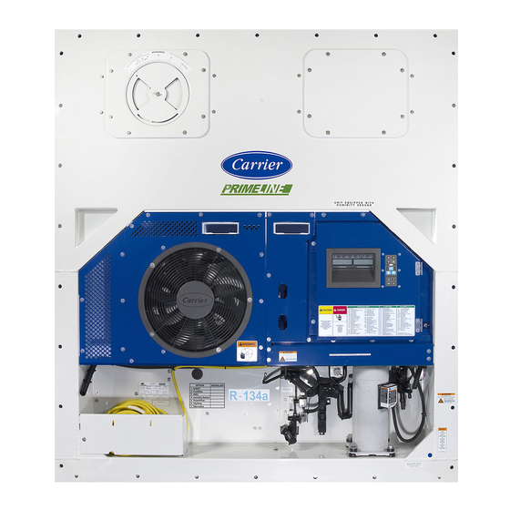
Sign In
Upload
Manuals
Brands
Carrier Manuals
Air Conditioner
PrimeLINE 69NT40-561-200
Carrier PrimeLINE 69NT40-561-200 Manuals
Manuals and User Guides for Carrier PrimeLINE 69NT40-561-200. We have
2
Carrier PrimeLINE 69NT40-561-200 manuals available for free PDF download: Operation And Service Manual
Carrier PrimeLINE 69NT40-561-200 Operation And Service Manual (184 pages)
Container Refrigeration Units
Brand:
Carrier
| Category:
Air Conditioner
| Size: 9.72 MB
Table of Contents
Table of Contents
6
Paragraph Number
15
Safety Summary
15
Introduction
19
Compressor
20
Autotransformer
21
Condenser Grille
22
Fuelwise
22
Quest
22
Figure Number
23
Description
23
General Description
23
Refrigeration Unit - Front Section
23
Figure 3.1 Refrigeration Unit - Front Section
23
Fresh Air Makeup Vent
24
Evaporator Section
24
Figure 3.2 Evaporator Section - Primeline
24
Figure 3.3 Evaporator Section - Primeline ONE
25
Compressor Section
26
Figure 3.4 Compressor Section
26
Air-Cooled Condenser Section
27
Figure 3.5 Air-Cooled Condenser Section
27
Water-Cooled Condenser Section
28
Figure 3.6 Tube in Shell Water-Cooled Condenser
28
Figure 3.7 Brazed Plate Water-Cooled Condenser
29
Control Box Section
30
Communications Interface Module
30
Figure 3.8 Control Box Section
30
Table Number
31
Refrigeration System Data
31
Table 3-1 Refrigeration System Data
31
Electrical Data
32
Table 3-2 Electrical Data
32
Safety and Protective Devices
33
Table 3-3 Safety and Protective Devices
33
Refrigeration Circuit
34
Standard Operation
34
Economized Operation
34
Electronic Expansion Valve
34
Figure 3.9 Refrigeration Circuit Schematic - Standard Operation
35
Figure 3.10 Refrigeration Circuit Schematic - Economized Operation
36
Figure 3.11 Refrigeration Circuit Schematic - Water-Cooled Condenser (Tube in Shell)
37
Figure 3.12 Refrigeration Circuit Schematic - Water-Cooled Condenser (Brazed Plate)
38
Microprocessor
39
Temperature Control Microprocessor System
39
Display Module and Keypad
39
Figure 4.1 Temperature Control System
39
Figure 4.2 Display Module
40
Figure 4.3 Keypad
40
Table 4-1 Display Module Leds
40
Table 4-2 Keypad Function
40
Controller
41
Controller Software
41
Figure 4.4 Control Module
41
Configuration Software (Cnf Variables)
42
Operational Software (CD Function Codes)
42
Modes of Operation
42
Start up - Compressor Phase Sequence
42
Start up - Compressor Bump Start
42
Perishable Mode Temperature Control
42
Perishable Pulldown
43
Perishable Steady State
43
Perishable Idle, Air Circulation
43
Perishable Heating
43
Figure 4.5 Controller Operation - Perishable Mode
43
Perishable Dehumidification
44
Perishable Dehumidification - Bulb Mode
44
Perishable Economy
45
Perishable Mode Cooling - Sequence of Operation
45
Figure 4.6 Perishable Mode Cooling
45
Perishable Mode Heating - Sequence of Operation
46
Figure 4.7 Perishable Mode Heating
46
Perishable Mode - Trim Heat
47
Frozen Mode - Temperature Control
47
Frozen Steady State
47
Frozen Idle Mode
47
Figure 4.8 Controller Operation - Frozen Mode
47
Frozen "Heat" Mode
48
Frozen Economy Mode
48
Frozen Mode Cooling - Sequence of Operation
48
Figure 4.9 Frozen Mode
48
Defrost
49
Defrost Operation
49
Defrost Related Settings
50
Figure 4.10 Defrost
50
Evaporator Fan Operation
51
Failure Action
51
Generator Protection
51
Compressor High Temperature Protection
51
Compressor Low Pressure Protection
51
Perishable Mode - System Pressure Regulation
51
Condenser Fan Override
52
Quest - Ccpc
52
Controller Alarms
52
Pre-Trip Diagnostics
53
Datacorder
53
Description
53
Datacorder Software
54
Sensor Configuration (Dcf02)
55
Logging Interval (Dcf03)
55
Thermistor Format (Dcf04)
56
Table 4-3 Datacorder Configuration Variables
56
Figure 4.11 Standard Configuration Download Report
57
Sampling Type (Dcf05 & Dcf06)
58
Alarm Configuration (Dcf07 - Dcf10)
58
Datacorder Power up
58
Table 4-4 Datacorder Standard Configurations
58
Pre-Trip Data Recording
59
Datacorder Communications
59
USDA Cold Treatment
59
USDA Cold Treatment Procedure
60
Datacorder Configuration Screen
60
Figure 4.12 Datacorder Probe Calibration Screen
61
Figure 4.13 Datacorder Probe Calibration Screen
61
Datacorder Alarms
62
Figure 4.14 Datacorder Systems Tool Screen
62
ISO Trip Header
63
Controller Configuration Variables
63
Table 4-5 Controller Configuration Variables
63
Controller Function Codes
65
Table 4-6 Controller Function Codes
65
Figure 4.15 Alarm Troubleshooting Sequence
74
4.10 Controller Alarm Indications
75
4.11 Controller Pre-Trip Test Codes
89
Table 4-7 Controller Pre-Trip Test Codes
89
Table 4-8 Datacorder Function Code Assignments
95
Table 4-9 Datacorder Pre-Trip Result Records
96
Table 4-10 Datacorder Alarm Indications
97
Operation
99
Inspection
99
Connect Power
99
Connecting to 380/460 VAC Power
99
Connecting to 190/230 VAC Power
99
Adjust Fresh Air Makeup Vent
100
Upper Fresh Air Makeup Vent
100
Figure 5.1 Autotransformer
100
Lower Fresh Air Makeup Vent
101
Figure 5.2 Upper Fresh Air Make up Flow Chart
101
Vent Position Sensor
102
Eautofresh Operation
102
Xtendfresh Operation
102
Connect Water-Cooled Condenser
102
Water-Cooled Condenser with Water Pressure Switch
102
Water-Cooled Condenser with Condenser Fan Switch
102
Connect Remote Monitoring Receptacle
103
Starting and Stopping Instructions
103
Starting the Unit
103
Stopping the Unit
103
Start-Up Inspection
103
Physical Inspection
103
Check Controller Function Codes
103
Start Temperature Recorder
104
Complete Inspection
104
5.10 Pre-Trip Diagnosis
104
5.11 Probe Diagnostics
106
Emergency Bypass Operation (Option)
106
Figure 5.3 Diagram of Emergency Bypass Connections
107
Tripwise (Option)
108
Checking Tripwise Status of the Container
108
Enabling or Disabling Tripwise with Function Code 65
109
Tripwise Status Event
109
Figure 5.4 Tripwise Status in Datacorder
109
Figure 5.5 Generating Tripwise Summary Report
109
Figure 5.6 Tripwise Summary Report
110
Automatic Cold Treatment (Option)
111
Troubleshooting
113
Unit will Not Start or Starts then Stops
113
Unit Operates Long or Continuously in Cooling
113
Unit Runs but Has Insufficient Cooling
114
Unit will Not Heat or Has Insufficient Heating
114
Unit will Not Terminate Heating
114
Unit will Not Defrost Properly
114
Abnormal Pressures
115
Abnormal Noise or Vibrations
115
Microprocessor Malfunction
116
6.10 no Evaporator Air Flow or Restricted Air Flow
116
6.11 Eautofresh Not Operating
116
6.12 Electronic Expansion Valve Malfunction
116
6.13 Autotransformer Malfunction
117
6.14 Water-Cooled Condenser or Water Pressure Switch
117
6.15 Compressor Operating in Reverse
117
6.16 Abnormal Temperatures
118
6.17 Abnormal Currents
118
Service
119
Section Layout
119
Manifold Gauge Set
119
Figure 7.1 Manifold Gauge Set
119
Evacuating the Manifold Gauge Set
120
Service Connections
120
Figure 7.2 Manifold Gauge/Hose Set
120
Connecting the Manifold Gauge Set
121
Removing the Manifold Gauge Set
121
Pump down the Unit
121
Figure 7.3 Service Valve
121
Automatic Pump down
122
Manual Pump down
122
Refrigerant Leak Checking
122
Evacuation and Dehydration
122
General
122
Preparation
123
Evacuate and Dehydrate - Complete System
123
Figure 7.4 Refrigeration System Service Connections
123
Evacuate and Dehydrate - Partial System
124
Refrigerant Charge
124
Adding Refrigerant to System - Full Charge
125
Figure 7.5 Compressor Kit
126
Removal and Replacement of Compressor
126
High Pressure Switch
127
Figure 7.6 High Pressure Switch Testing
128
Condenser Coil Removal
129
Figure 7.7 Condenser Fan Position
130
Condenser Fan and Fan Motor
131
Cleaning Supplies Needed
132
Figure 7.8 Water-Cooled Condenser Cleaning - Forced Circulation
133
Figure 7.9 Water-Cooled Condenser Cleaning - Gravity Circulation
133
Filter Drier
134
Figure 7.10 Heater Arrangement
135
Evaporator Heaters
135
Evaporator Fan and Motor Assembly
137
Figure 7.11 Evaporator Fan Assembly
138
Figure 7.12 Access Panel Torque Pattern
138
Evaporator Section Cleaning
138
Cleaning Preparation
139
Figure 7.13 Electronic Expansion Valve
140
Installing an EEV
140
Figure 7.14 Coil View of Economizer Solenoid Valve (ESV)
142
Figure 7.15 Economizer Expansion Valve
143
Installing the Solenoid Valve Coil
143
Figure 7.16 Adapter and O-Ring
144
Troubleshooting P6-7 (Duv)
144
Digital Unloader Valve (Duv)
145
Removing the DUV
145
Installing the DUV
145
Figure 7.17 View of Digital Unloader Valve (DUV) Assembly
145
7.25 Valve Override Controls
146
Table 7-1 Valve Override Control Displays
146
Autotransformer
147
7.27 Controller
147
Handling Modules
147
Figure 7.18 Autotransformer
147
Controller Troubleshooting
148
Controller Programming Procedure
148
Figure 7.19 Controller Section of the Control Box
148
Loading Operational Software
149
Loading Configuration Software
149
Setting the Date and Time
150
Setting the Container ID
150
Removing and Installing a Controller
150
Battery Replacement
151
7.28 Temperature Sensor Service
151
Sensor Checkout Procedure
151
Table 7-2 Sensor Resistance - AMBS, DTS, ETS, RRS, RTS, SRS, STS
152
Table 7-3 Sensor Resistance - CPDS
154
Sensor Replacement
155
Figure 7.20 Sensor Types
156
Figure 7.21 Sensor and Cable Splice
156
Sensor STS and SRS Reinstallation
157
Sensor RRS and RTS Reinstallation
157
Figure 7.22 Supply Sensor Positioning
157
Figure 7.23 Return Sensor Positioning
157
Sensor DTS Reinstallation
158
Sensor ETS1 and ETS2 Reinstallation
158
Sensor, CPDS Reinstallation
158
Figure 7.24 Evaporator Temperature Sensor Positioning
158
Figure 7.25 Compressor Discharge Temperature Sensor
158
Vent Position Sensor (Vps)
159
7.30 Eautofresh Service
159
7.31 Xtendfresh Service
159
7.32 Maintenance of Painted Surfaces
159
7.33 Communications Interface Module Installation
160
Figure 7.26 Communications Interface Installation
160
Table 7-4 R-134A Refrigerant Pressure Temperature Chart
161
Table 7-5 R-513A Refrigerant Pressure Temperature Chart
164
Table 7-6 Recommended Bolt Torque Values (Dry, Non-Lubricated for 18-8 Stainless Steel)
167
Electrical Wiring Schematic and Diagrams
169
Figure 8.1 LEGEND - Standard Unit Configuration
169
Figure 8.2 SCHEMATIC DIAGRAM
170
Figure 8.3 UNIT WIRING DIAGRAM (Sheet 1 of 2)
171
Figure 8.4 UNIT WIRING DIAGRAM (Sheet 2 of 2)
172
Figure 8.5 LEGEND - Unit with Transformer
173
Figure 8.6 SCHEMATIC DIAGRAM - Unit with Transformer
174
Figure 8.7 UNIT WIRING DIAGRAM, Unit with Autotransformer (Sheet 1 of 2)
175
Figure 8.8 UNIT WIRING DIAGRAM - Unit with Transformer (Sheet 2 of 2)
176
Eu Declaration of Conformity
177
Index
181
Advertisement
Carrier PrimeLINE 69NT40-561-200 Operation And Service Manual (198 pages)
Container Refrigeration Units
Brand:
Carrier
| Category:
Industrial Equipment
| Size: 9.16 MB
Table of Contents
Table of Contents
4
Description
23
3.1 General Description
23
Refrigeration Unit - Front Section
23
Figure 3.1 Refrigeration Unit - Front Section
23
Compressor Section
24
Air-Cooled Condenser Section
24
Figure 3.2 Compressor Section
24
Figure 3.3 Condenser Section with "C" Shape Coil (Pids < NT3000)
25
Figure 3.4 Condenser Section, with MCHE and Steel Receiver (Pids NT3000 to NT3099)
26
Figure 3.5 Condenser Section, with MCHE and Aluminum Receiver (Pids > NT3100)
27
Water-Cooled Condenser Section
28
Figure 3.6 Tube in Shell Water-Cooled Condenser
28
Fresh Air Makeup Vent
29
Evaporator Section
29
Figure 3.7 Brazed Plate Water-Cooled Condenser
29
Figure 3.8 Evaporator Section
30
Figure 3.9 Evaporator Section - Primeline ONE
31
Control Box Section
32
Communications Interface Module
32
Figure 3.10 Control Box Section
32
3.2 Refrigeration System Data
33
Table 3-1 Refrigeration System Data
33
3.3 Electrical Data
34
Table 3-2 Electrical Data
34
3.4 Safety and Protective Devices
35
Electronic Expansion Valve (EEV)
35
Table 3-3 Safety and Protective Devices
35
Figure 3.11 Refrigeration Circuit Schematic - Standard Operation
37
Figure 3.12 Refrigeration Circuit Schematic - Economized Operation
38
Figure 3.13 Refrigeration Circuit Schematic - Water-Cooled Condenser (Tube in Shell)
39
Figure 3.14 Refrigeration Circuit Schematic - Water-Cooled Condenser (Brazed Plate)
40
Microprocessor
41
4.1 Temperature Control Microprocessor System
41
Controller
41
Display Module and Keypad
41
Figure 4.1 Controller
41
Figure 4.2 Display Module and Keypad
41
Table 4-1 Display Module Leds
42
Table 4-2 Keypad Function
42
4.2 Controller Software
43
Configuration Software (Cnf Variables)
43
Table 4-3 Controller Configuration Variables
43
Operational Software (CD Function Codes)
44
Table 4-4 Controller Function Codes
45
4.3 Modes of Operation
59
Start up - Compressor Phase Sequence
59
Start up - Compressor Bump Start
59
Perishable Mode Temperature Control
59
Perishable Pulldown
59
Perishable Steady State
59
Perishable Idle, Air Circulation
59
Perishable Heating
60
Perishable Dehumidification
60
Figure 4.3 Controller Operation - Perishable Mode
60
Perishable Dehumidification - Bulb Mode
61
Perishable Economy
61
Perishable Mode Cooling - Sequence of Operation
62
Figure 4.4 Perishable Mode Cooling
62
Perishable Mode Heating - Sequence of Operation
63
Perishable Mode - Trim Heat
63
Frozen Mode - Temperature Control
63
Frozen Steady State
63
Figure 4.5 Perishable Mode Heating
63
Frozen Idle Mode
64
Frozen "Heat" Mode
64
Frozen Economy Mode
64
Frozen Mode Cooling - Sequence of Operation
64
Figure 4.6 Controller Operation - Frozen Mode
64
Defrost
65
Figure 4.7 Frozen Mode
65
Defrost Operation
66
Defrost Related Settings
67
Figure 4.8 Defrost
67
Protection Modes of Operation
68
QUEST Mode
68
4.4 Controller Alarms
69
Table 4-5 Alarm Indications and Descriptions
70
4.5 Pre-Trip Diagnostics
82
Controller Pre-Trip Test Codes
82
Table 4-6 Controller Pre-Trip Test Codes
82
4.6 Datacorder
88
Datacorder Description
88
Datacorder Configuration Software
89
Table 4-7 Datacorder Configuration Variables
89
Table 4-8 Sensor Configuration
90
Datacorder Operational Software
91
Table 4-9 Datacorder Function Code Assignments
92
Datacorder Power up
93
Datacorder Alarms
93
Table 4-10 Datacorder Alarm Indications
94
Pre-Trip Data Recording
95
Table 4-11 Datacorder Pre-Trip Result Records
95
Datacorder Communications
96
USDA Cold Treatment
97
Figure 4.9 Datacorder Configuration Screen
97
Figure 4.10 Datacorder Probe Calibration Screen
98
ISO Trip Header
99
Figure 4.11 Datacorder Probe Calibration Screen
99
Figure 4.12 Datacorder Systems Tool Screen
99
Operation
101
5.1 Inspection
101
5.2 Connect Power
101
Connecting to 380/460 VAC Power
101
Connecting to 190/230 VAC Power
101
5.3 Adjust Fresh Air Makeup Vent
102
Upper Fresh Air Makeup Vent
102
Figure 5.1 Autotransformer
102
Lower Fresh Air Makeup Vent
103
Figure 5.2 Upper Fresh Air Make up Flow Chart
103
Vent Position Sensor
104
5.4 Connect Water-Cooled Condenser
104
Water-Cooled Condenser with Water Pressure Switch
104
Water-Cooled Condenser with Condenser Fan Switch
104
5.5 Connect Remote Monitoring Receptacle
105
5.6 Starting and Stopping Instructions
105
Starting the Unit
105
Stopping the Unit
105
5.7 Start-Up Inspection
105
Physical Inspection
105
Check Controller Function Codes
105
Start Temperature Recorder
105
Complete Inspection
105
5.8 Pre-Trip Diagnosis
106
Prior to Starting a Pre-Trip
106
Starting a Pre-Trip
106
Displaying Pre-Trip Test Results
107
5.9 Probe Diagnostics
107
5.10 Optional Operating Modes
108
Emergency Bypass Operation
108
Tripwise
109
Figure 5.3 Diagram of Emergency Bypass Connections
109
Figure 5.4 Tripwise Status in Datacorder
110
Xtendfresh
111
Figure 5.5 Generating Tripwise Summary Report
111
Automatic Cold Treatment Mode
112
Automatic Setpoint Change Mode
113
Quest Mode
114
Fuelwise Mode
114
Figure 6.1 Unit Troubleshooting Sequence
115
Microprocessor Malfunction
119
6.10 no Evaporator Air Flow or Restricted Air Flow
119
6.11 Xtendfresh Not Operating
119
6.12 Electronic Expansion Valve Malfunction
119
6.13 Autotransformer Malfunction
120
6.14 Water-Cooled Condenser or Water Pressure Switch
120
Compressor Operating in Reverse
120
Abnormal Temperatures
120
Abnormal Currents
120
Service
121
Section Layout
121
Manifold Gauge Set
121
Figure 7.1 Manifold Gauge Set
121
Evacuating the Manifold Gauge Set
122
Service Connections
122
Figure 7.2 Manifold Gauge / Hose Set
122
Connecting the Manifold Gauge Set
123
Removing the Manifold Gauge Set
123
Pump down the Unit
123
Figure 7.3 Service Valve
123
Automatic Pump down
124
Manual Pump down
124
Refrigerant Leak Checking
124
Evacuation and Dehydration
125
General
125
Preparation
125
Evacuate and Dehydrate - Complete System
125
Figure 7.4 Refrigeration System Service Connections
125
Evacuate and Dehydrate - Partial System
126
Checking the Refrigerant Charge
126
Adding Refrigerant to System - Full Charge
127
Adding Refrigerant to System - Partial Charge
127
Converting to R-513A Refrigerant
127
Compressor
128
Removing and Replacing the Compressor
128
Figure 7.5 Compressor Kit
129
7.10 High Pressure Switch
130
Checking High Pressure Switch
130
Figure 7.6 High Pressure Switch Testing
130
Replacing High Pressure Switch
131
7.11 Condenser Coil
131
Condenser Coil Cleaning
131
Condenser Coil Removal
131
Condenser Coil Preparation
132
Figure 7.7 Condenser Fan Position
133
Figure 7.8 Water-Cooled Condenser Cleaning - Forced Circulation
139
Figure 7.9 Water-Cooled Condenser Cleaning - Gravity Circulation
140
Figure 7.10 Heater Arrangement
141
Figure 7.11 Evaporator Fan Assembly
144
Figure 7.12 Access Panel Torque Pattern
145
Figure 7.13 Electronic Expansion Valve (EEV)
146
Figure 7.14 Coil View of Economizer Solenoid Valve (ESV)
149
Figure 7.15 Economizer Expansion Valve
150
Figure 7.16 Adapter and O-Ring
151
Figure 7.17 View of Digital Unloader Valve (DUV) Assembly
152
Table 7-1 Valve Override Control Displays
153
Figure 7.18 Autotransformer
154
Figure 7.19 Controller
155
Table 7-2 Test Point Descriptions
155
Table 7-3 Sensor Resistance - AMBS, DTS, ETS, RRS, RTS, SRS, STS
162
Table 7-4 Sensor Resistance - Primeline CPDS
163
Figure 7.20 Supply Sensors - Cover Assembly and Sensors
164
Figure 7.21 Removing Front Access Panels
165
Figure 7.22 Removing Evaporator Motor
165
Figure 7.23 Return Sensors - Bracket
165
Figure 7.24 Return Sensors - Cutting Wire Ties
166
Figure 7.25 Dataline - Probe Calibration
166
Figure 7.26 Dataline - Calibrate Sensors Button
167
Figure 7.27 Dataline - Enter Service Center Information
167
Figure 7.28 Ice Bath
168
Figure 7.29 Dataline - Start Cal Button
168
Figure 7.30 Dataline - Calibration Results
169
Figure 7.31 Sensor Types
170
Figure 7.32 Sensor and Cable Splice
170
Figure 7.33 STS/SRS Positioning
171
Figure 7.34 RRS/RTS Positioning
171
Figure 7.35 ETS1/ETS2 Positioning
172
Figure 7.36 Compressor Discharge Temperature Sensor
172
Figure 7.37 Communications Interface Installation
174
Table 7-5 R-134A Refrigerant Pressure Temperature Chart
175
Table 7-6 R-513A Refrigerant Pressure Temperature Chart
178
Table 7-7 Recommended Bolt Torque Values (Dry, Non-Lubricated for 18-8 Stainless Steel)
181
Figure 8.1 LEGEND - Standard Unit Configuration
183
Figure 8.2 Schematic Diagram
184
Figure 8.3 Unit Wiring Diagram (Sheet 1 of 2)
185
Figure 8.4 Unit Wiring Diagram (Sheet 2 of 2)
186
Figure 8.5 Legend - Unit with Auto Transformer
187
Figure 8.6 Schematic Diagram - Unit with Auto Transformer
188
Figure 8.7 Unit Wiring Diagram - Unit with Auto Transformer (Sheet 1 of 2)
189
Figure 8.8 Unit Wiring Diagram - Unit with Auto Transformer (Sheet 2 of 2)
190
Advertisement
Related Products
Carrier PrimeLINE 69NT40-561-299
Carrier PrimeLINE 69NT40-561-599
Carrier PrimeLINE 69NT40-561-500
Carrier PrimeLINE ONE 69NT40-565-299
Carrier PrimeLINE ONE 69NT40-565-599
Carrier PrimeLINE ONE 69NT40-565-500
Carrier PrimeLINE ONE 69NT40-565-200
Carrier 69NT40-561-201
Carrier 68RM35-610-2
Carrier 619FEQ009BBGA
Carrier Categories
Air Conditioner
Heat Pump
Furnace
Thermostat
Chiller
More Carrier Manuals
Login
Sign In
OR
Sign in with Facebook
Sign in with Google
Upload manual
Upload from disk
Upload from URL