Table of Contents
Troubleshooting

Subscribe to Our Youtube Channel
Related Manuals for Carrier PrimeLINE 69NT40-561-200


Summary of Contents for Carrier PrimeLINE 69NT40-561-200
- Page 1 Container Refrigeration OPERATIONS AND SERVICE MANUAL PrimeLINE 69NT40-561-200 to 299 69NT40-561-500 to 599 PrimeLINE ONE 69NT40-565-200 to 299 69NT40-565-500 to 599 Container Refrigeration Units T-362 Rev G...
- Page 3 OPERATIONS AND SERVICE MANUAL PrimeLINE 69NT40-561-200 to 299 69NT40-561-500 to 599 PrimeLINE ONE 69NT40-565-200 to 299 69NT40-565-500 to 599 Container Refrigeration Units © 2018 Carrier Corporation Printed in USA November 2018 ●...
- Page 5 TABLE OF CONTENTS PARAGRAPH NUMBER PAGE SAFETY SUMMARY ..............1–1 GENERAL SAFETY NOTICES .
-
Page 6: Table Of Contents
2.5.26 FuelWise ..............2–4 2.5.27 Quest . - Page 7 4.3.22 Defrost Related Settings ..........4–12 4.3.23 Evaporator Fan Operation .
- Page 8 5.8.2 Stopping the Unit ............5–5 START-UP INSPECTION .
- Page 9 7.7.1 Checking the Refrigerant Charge ..........7–6 7.7.2 Adding Refrigerant to System - Full Charge...
- Page 10 7.24 DIGITAL UNLOADER VALVE (DUV) ..........7–27 7.24.1 Removing the DUV .
- Page 11 LIST OF ILLUSTRATIONS FIGURE NUMBER Page Figure 3.1 Refrigeration Unit - Front Section ..........3–1 Figure 3.2 Evaporator Section - PrimeLINE .
- Page 12 Figure 7.10 Heater Arrangement ............7–17 Figure 7.11 Evaporator Fan Assembly .
- Page 13 LIST OF TABLES TABLE NUMBER Page Table 3–1 Refrigeration System Data ............3–9 Table 3–2 Electrical Data .
-
Page 15: Safety Summary
SECTION 1 SAFETY SUMMARY GENERAL SAFETY NOTICES Installation and servicing of refrigeration equipment can be hazardous due to system pressures and electrical com- ponents. Only trained and qualified service personnel should install, repair, or service refrigeration equipment. When working on refrigeration equipment, observe all potential Danger, Warning and Caution hazards, including those shown below and on hazard labels attached to the unit. - Page 16 WARNING EXPLOSION HAZARD: Failure to follow this WARNING can result in death, serious personal injury and / or property damage. Never use air or gas mixtures containing oxygen (O ) for leak testing or operating the product. Charge only with refrigerants R-134a or R-513A as specified for the unit model number: Refrigerant must conform to AHRI Standard 700 specification.
- Page 17 WARNING Always turn OFF the unit circuit breakers (CB-1 & CB-2) and disconnect main power supply before working on moving parts. WARNING Installation requires wiring to the main unit circuit breaker, CB-1. Make sure the power to the unit is off and power plug disconnected before beginning installation. CAUTION When charging the unit with R-513A refrigerant, charge as a liquid only.
- Page 18 CAUTION When Pre-Trip test Auto 2 runs to completion without being interrupted, the unit will terminate pre-trip and display “Auto 2” “end.” The unit will suspend operation until the user depresses the ENTER key! CAUTION The unit will remain in the full cooling mode as long as the EB switch is in the On position and the Mode Switch is in the Full Cool position.
-
Page 19: Introduction
INTRODUCTION INTRODUCTION The Carrier Transicold PrimeLINE models 69NT40-561-200 to 299 and 69NT40-561-500 to 599 are units of light- weight aluminum frame construction, designed to be bolted on to the front of a container and serve as the con- tainer’s front wall. Forklift pockets are provided for unit installation and removal. -
Page 20: Compressor
2.4.4 Compressor The unit is fitted with either an R-134a or an R-513A scroll compressor equipped with suction and discharge ser- vice connections. To identify an R-513A-ready compressor in the field, a green dot is located on the top of the com- pressor on the DUV fitting. -
Page 21: Autotransformer
2.5.8 Autotransformer An autotransformer may be provided to allow operation on 190/230, 3-phase, 50/60 Hz power. The autotrans- former raises the supply voltage to the nominal 380/460 volt power required by the base unit. The autotransformer may also be fitted with an individual circuit breaker for the 230 volt power. If the unit is equipped with an autotransformer and communications module, the autotransformer will be fitted with a transformer bridge unit (TBU) to assist in communications. -
Page 22: Fuelwise
NOTE Repaired controllers are NOT to be used for warranty repairs; only full OEM Re-manufactured control- lers are to be used. Controllers will be factory-equipped with the latest version of operational software, but will NOT be configured for a specific model number and will need to be configured at the time of installation or sale. 2.5.21 Condenser Grille Condenser grilles are direct bolted. -
Page 23: Description
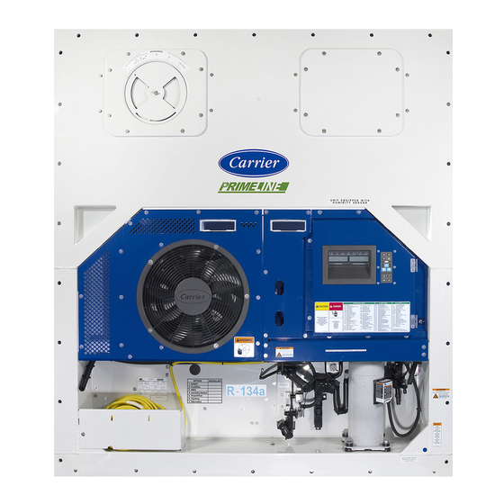
SECTION 3 DESCRIPTION GENERAL DESCRIPTION 3.1.1 Refrigeration Unit - Front Section The unit is designed so that the majority of the components are accessible from the front (see Figure 3.1). The unit model number, serial number and parts identification number can be found on the unit nameplate on the back wall of the condenser section. -
Page 24: Fresh Air Makeup Vent
3.1.2 Fresh Air Makeup Vent The function of the upper or lower makeup air vent is to provide ventilation for commodities that require fresh air circulation. A manually operated venting system is located in the upper left access panel. 3.1.3 Evaporator Section The evaporator section is shown in Figure... -
Page 25: Figure 3.3 Evaporator Section - Primeline One
Figure 3.3 Evaporator Section - PrimeLINE ONE 1. Evaporator Fan #1 7. Defrost Temperature Sensor (DTS) 2. Evaporator Fan #2 8. Heat Termination Thermostat (HTT) 3. Return Recorder Sensor / Return Temperature 9. Electronic Expansion Valve (EEV) Sensor (RRS / RTS) 10. -
Page 26: Compressor Section
3.1.4 Compressor Section The compressor section (see Figure 3.4) includes the compressor, digital unloader valve (DUV), high pressure switch, discharge pressure transducer (DPT), evaporator pressure transducer (EPT) and the suction pressure transducer (SPT). The supply temperature sensor and supply recorder sensor are located to the left of the com- pressor. -
Page 27: Air-Cooled Condenser Section
3.1.5 Air-Cooled Condenser Section The air-cooled condenser section (see Figure 3.5) consists of the condenser fan, condenser coil, receiver, liquid line service valve, filter drier, fusible plug, economizer, economizer expansion valve, economizer solenoid valve (ESV), and sight glass/moisture indicator. The condenser fan pulls air from around the coil and discharges it hori- zontally through the condenser fan grille. -
Page 28: Water-Cooled Condenser Section
3.1.6 Water-Cooled Condenser Section The unit may contain a water-cooled condenser (wcc) installed as an option. When operating on the water-cooled condenser, the condenser fan is deactivated by a water pressure switch or condenser fan switch. There are two types of water-cooled condensers available and both are described below. a. -
Page 29: Figure 3.7 Brazed Plate Water-Cooled Condenser
b. Brazed Plate Water-Cooled Condenser The brazed plate water-cooled condenser section (see Figure 3.7) consists of the brazed plate water-cooled con- denser, water couplings, a water pressure switch and a fusible plug. The receiver is retained in this configuration and the brazed plate heat exchanger is placed between the air-cooled condenser and the receiver. Figure 3.7 Brazed Plate Water-Cooled Condenser 1. -
Page 30: Control Box Section
3.1.7 Control Box Section The control box (see Figure 3.8) includes: the manual operation switches, circuit breaker (CB-1), compressor, fan and heater contactors, control power transformer, fuses, keypad, display module, current sensor module, controller module and the communications interface module. Figure 3.8 Control Box Section 1. -
Page 31: Refrigeration System Data
REFRIGERATION SYSTEM DATA Table 3–1 Refrigeration System Data a. Compressor/Motor Model Number ZMD26KVE-TFD-272 Assembly Weight (With Oil) 42.9 kg (95 lb) Approved Oil Uniqema Emkarate RL-32-3MAF Oil Charge 1774 ml (60 ounces) b. Electronic Expansion Verify at - 18°C (0°F) 4.4 to 6.7°C (8 to 12°F) Valve Superheat container box temperature... -
Page 32: Electrical Data
ELECTRICAL DATA Table 3–2 Electrical Data CB-1 (25 amp) Trips at 29 amps a. Circuit Breaker CB-2 (50 amp) Trips at 62.5 amps CB-2 (70 amp) Trips at 87.5 amps b. Compressor Motor Full Load Amps (FLA) 13 amps @ 460 VAC Nominal Supply 380 VAC / 3 Phase / 50 Hz 460 VAC / 3 Phase / 60 Hz Full Load Amps... -
Page 33: Safety And Protective Devices
Table 3–2 Electrical Data (Continued) Coil Feed to Ground 47 ohms j. EEV Nominal (Gray Wire) Resistance Coil Feed to Coil Feed 95 ohms Orange wire Power Red wire Output Brown wire Ground Input voltage 5 VDC Output voltage 0 to 3.3 VDC k. -
Page 34: Refrigeration Circuit
REFRIGERATION CIRCUIT 3.5.1 Standard Operation Starting at the compressor, (see Figure 3.9) the suction gas is compressed to a higher pressure and temperature. The refrigerant gas flows through the discharge line and continues into the air-cooled condenser. When operating with the air-cooled condenser active, air flowing across the coil fins and tubes cools the gas to saturation tempera- ture. -
Page 35: Figure 3.9 Refrigeration Circuit Schematic - Standard Operation
Figure 3.9 Refrigeration Circuit Schematic - Standard Operation 1. Compressor 13. Economizer TXV Sensing Bulb 2. Discharge Service Valve 14. Economizer 3. Discharge Pressure Transducer 15. Economizer Connection 4. Condenser 16. Electronic Expansion Valve (EEV) 5. Fusible Plug 17. Evaporator 6. -
Page 36: Figure 3.10 Refrigeration Circuit Schematic - Economized Operation
Figure 3.10 Refrigeration Circuit Schematic - Economized Operation 1. Compressor 13. Economizer TXV Sensing Bulb 2. Discharge Service Valve 14. Economizer 3. Discharge Pressure Transducer 15. Economizer Connection 4. Condenser 16. Electronic Expansion Valve (EEV) 5. Fusible Plug 17. Evaporator 6. -
Page 37: Figure 3.11 Refrigeration Circuit Schematic - Water-Cooled Condenser (Tube In Shell)
Figure 3.11 Refrigeration Circuit Schematic - Water-Cooled Condenser (Tube In Shell) 1. Compressor 14. Economizer Solenoid Valve 2. Discharge Service Valve 15. Economizer Thermal Expansion Valve 3. Discharge Pressure Transducer 16. Economizer TXV Sensing Bulb 4. Condenser 17. Economizer 5. Rupture Disk 18. -
Page 38: Figure 3.12 Refrigeration Circuit Schematic - Water-Cooled Condenser (Brazed Plate)
Figure 3.12 Refrigeration Circuit Schematic - Water-Cooled Condenser (Brazed Plate) 1. Compressor 15. Economizer Solenoid Valve 2. Discharge Service Valve 16. Economizer Thermal Expansion Valve 3. Discharge Pressure Transducer 17. Economizer TXV Sensing Bulb 4. Condenser 18. Economizer 5. Water-Cooled Condenser 19. -
Page 39: Microprocessor
SECTION 4 MICROPROCESSOR TEMPERATURE CONTROL MICROPROCESSOR SYSTEM The temperature control Micro-Link 3 microprocessor system (see Figure 4.1) consists of a keypad, display mod- ule, control module (controller) and interconnecting wiring. The controller houses the temperature control software and the DataCORDER software. The temperature control software functions to operate the unit components as required to provide the desired cargo temperature and humidity. -
Page 40: Figure 4.2 Display Module
Figure 4.2 Display Module Figure 4.3 Keypad CODE SELECT TRIP MANUAL ALARM DEFROST/ LIST INTERVAL ENTER RETURN SUPPLY BATTERY POWER MODE Table 4–1 Display Module LEDs Table 4–2 Keypad Function LIGHT FUNCTION FUNCTION COOL Energized when the refrigerant compres- CODE SELECT Access function codes. (White / Blue) sor is energized. -
Page 41: Controller
The control module (see Figure 4.4) is fitted with test points, harness connectors and a software card program- ming port. Figure 4.4 Control Module EN12830 CONTROLLER With CARRIER REV 5147 YYWW: 1035 12-00579-00 Micro-Link3 S/N: 0491162 DataCORDER 59980 T B C1 1. -
Page 42: Configuration Software (Cnf Variables)
4.2.1 Configuration Software (CnF Variables) Configuration software is a variable listing of the components available for use by the operational software. This software is factory installed in accordance with the equipment fitted and options listed on the original purchase order. Changes to the configuration software are required only when a new controller has been installed or a phys- ical change has been made to the unit such as the addition or removal of an option. -
Page 43: Perishable Pulldown
4.3.4 Perishable Pulldown When the system is in Perishable Pulldown mode, the highest priority is given to bringing the container down to setpoint. When cooling from a temperature that is more than 2.5°C (4.5°F) above setpoint, the system will be in Perishable Pulldown mode in economized operation. -
Page 44: Perishable Dehumidification
4.3.8 Perishable Dehumidification Dehumidification is provided to reduce the humidity levels inside the container. The dehumidification setpoint range is from 50% to 95%. Dehumidification is activated when a humidity value is set at Cd33. The yellow SUPPLY LED will flash ON and OFF every second to indicate that Dehumidification is active. Once Dehumidification is active and the following conditions are satisfied, the controller will activate the heat relay to begin Dehumidification. -
Page 45: Perishable Economy
4.3.10 Perishable Economy Economy Fan mode is an extension of the Perishable mode, and is provided for power saving purposes. Economy Fan mode is activated when Cd34 (also used for Frozen Economy mode) is set to “ON.” Economy Fan mode is used in the transportation of temperature-tolerant cargo or non-respiration items which do not require high airflow for removing respiration heat. -
Page 46: Perishable Mode Heating - Sequence Of Operation
d. When unloaded cooling starts, EEV control will transition from a full cool superheat setpoint to a lower mod- ulated cool superheat setpoint. Once unloading starts, the EEV controls evaporator superheat based on the system duty cycle where instantaneous superheat will vary. e. -
Page 47: Perishable Mode - Trim Heat
4.3.13 Perishable Mode - Trim Heat If the system capacity has been decreased to the lowest allowable capacity and conditions exist that warrant max- imum temperature stability the controller will pulse the HR relay to energize the evaporator heaters in sequence with the compressor digital signal. -
Page 48: Frozen "Heat" Mode
4.3.17 Frozen “Heat” Mode If the temperature drops 10°C (18°F) below setpoint, the unit will transition to the Frozen “Heating” mode. The evaporator fans are brought to high speed, and the heat from the fans is circulated through the container. The unit will transition back to Frozen Steady State when the temperature rises back to the transition point. -
Page 49: Defrost
4.3.20 Defrost Defrost is initiated to remove ice buildup from the evaporator coil which can obstruct air flow and reduce the cooling capacity of the unit. The defrost cycle may consist of up to three distinct operations depending upon the reason for the defrost or model number configuration. -
Page 50: Defrost Related Settings
3. Probe Check: If defrost is initiated due to Probe Check immediately following the defrost cycle the evapora- tion fans are started and run for eight minutes to stabilize the temperature throughout the container. A probe check comparison is carried out at the end of the eight minute period if any sensor is found out of calibration. At this time its alarm set is no longer used for control/reorder purposes. -
Page 51: Evaporator Fan Operation
Defrost Timer If CnF23 is configured to “SAv” (save), then the value of the defrost interval timer will be saved at power down and restored at power up. This option prevents short power interruptions from resetting an almost expired defrost inter- val, and possibly delaying a needed defrost cycle. -
Page 52: Condenser Fan Override
4.3.29 Condenser Fan Override When CnF17 (Discharge Temperature Sensor) is set to “In” and CnF48 (Condenser Fan Switch Override) is set to “On”, the condenser fan switch override logic is activated. If condenser cooling water pressure is sufficient to open the water pressure switch (de-energizing the condenser fan) when water flow or pressure conditions are not main- taining discharge temperature, the logic will energize the condenser fan as follows: 1. -
Page 53: Pre-Trip Diagnostics
4.7.1 Description Carrier Transicold “DataCORDER” software is integrated into the controller and serves to eliminate the tempera- ture recorder and paper chart. DataCORDER functions may be accessed by keypad selections and viewed on the display module. The unit is also fitted with interrogation connections (see Figure 4.1) which may be used with the... -
Page 54: Datacorder Software
d. Records DataCORDER and temperature control software generated data and events as follows: • Container ID Change • Software Upgrades • Alarm Activity • Battery Low (battery pack) • Data Retrieval • Defrost Start and End • Dehumidification Start and End •... -
Page 55: Sensor Configuration (Dcf02)
Changing the configuration to generic and selecting which data points to record may be done using the Carrier Transicold Data Retrieval Program. A list of the data points avail- able for recording follows. -
Page 56: Thermistor Format (Dcf04)
4.7.5 Thermistor Format (dCF04) The user may configure the format in which the thermistor readings are recorded. The short resolution is a 1 byte format and the long resolution is a 2 byte format. The short requires less memory and records temperature with variable resolutions depending on temperature range. -
Page 57: Figure 4.11 Standard Configuration Download Report
Figure 4.11 Standard Configuration Download Report Raw Data Report for ABC1234567 Jan 01, 2015 to Mar 01, 2015 System Configuration at the Time of Interrogation: Interrogated On Mar 05, 2015 Extracted by DataLINE Rev 1.0.0 Controller Software: 5361 Controller Serial #: 04163552 Bill of Lading #: 1 Origin: Origin Date:... -
Page 58: Sampling Type (Dcf05 & Dcf06)
Table 4–4 DataCORDER Standard Configurations STANDARD CONFIG DESCRIPTION 2 sensors (dCF02=2) 2 thermistor inputs (supply & return) 5 sensors (dCF02=5) 2 thermistor inputs (supply & return) 3 USDA thermistor inputs 6 sensors (dCF02=6) 2 thermistor inputs (supply & return) 3 USDA thermistor inputs 1 humidity input 9 sensors (dCF02=9) Not Applicable... -
Page 59: Pre-Trip Data Recording
T107, T108, and T109 of the USDA Treatment Manual. In response to the demand to replace fumigation with this environmentally sound process, Carrier has integrated Cold Treatment capability into its microprocessor system. These units have the ability to maintain supply air tem- perature within one quarter degree Celsius of set point and record minute changes in product temperature within the DataCORDER memory, thus meeting USDA criteria. -
Page 60: Usda Cold Treatment Procedure
a. USDA Recording A special type of recording is used for USDA cold treatment purposes. Cold treatment recording requires three remote temperature probes be placed at prescribed locations in the cargo. Provision is made to con- nect these probes to the DataCORDER via receptacles located at the rear left-hand side of the unit. Four or five receptacles are provided. -
Page 61: Figure 4.12 Datacorder Probe Calibration Screen
Figure 4.12 DataCorder Probe Calibration Screen 3. Pre-cool the container to the treatment temperature or below. 4. Install the DataCORDER module battery pack (if not already installed). 5. Place the three probes. Refer to USDA Treatment Manual for directions on placement of probes in fruit and probe locations in container. -
Page 62: Datacorder Alarms
c.Using the System Tools screen in the DataLine software perform a “trip start.” (Refer to figure below) Figure 4.14 DataCorder Systems Tool Screen 4.7.14 DataCORDER Alarms The alarm display is an independent DataCORDER function. If an operating parameter is outside of the expected range or a component does not return the correct values to the DataCORDER, an alarm is generated. -
Page 63: Iso Trip Header
4.7.15 ISO Trip Header DataLINE provides the user with an interface to view/ modify current settings of the ISO trip header through the ISO Trip Header screen. The ISO Trip Header screen is displayed when the user clicks on the “ISO Trip Header” button in the “Trip Func- tions”... - Page 64 Table 4–5 Controller Configuration Variables (Continued) CONFIG TITLE DEFAULT OPTION CnF41 Enable Low DTT Setting CnF44 Autoslide Enable LO, UP CnF45 Low Humidity Enabled CnF46 Quench / Liquid Injection Valve Type nO=0=no nC=1=nc CnF47 Vent Position UP, LOW, CUStOM CnF49 OEM Reset Option 0-off,1-std, 2-spec,3-cust CnF50...
-
Page 65: Controller Function Codes
CONTROLLER FUNCTION CODES Table 4–6 Controller Function Codes CODE TITLE DESCRIPTION Note: If the function is not applicable, the display will read “-----” Display Only Functions - Cd01 through Cd26 are display only functions. Display Only Functions Cd01 Digital Unloader Displays the DUV percent closed. - Page 66 Table 4–6 Controller Function Codes (Continued) CODE TITLE DESCRIPTION Cd19 Battery Check This code checks the Controller/DataCORDER battery pack. While the test is running, “btest” will flash on the right display, followed by the result. “PASS” will be displayed for battery voltages greater than 7.0 volts. “FAIL” will be displayed for battery voltages between 4.5 and 7.0 volts, and “-----”...
- Page 67 Table 4–6 Controller Function Codes (Continued) CODE TITLE DESCRIPTION Cd29 Failure Action (Mode) If all of the control sensors are out of range (alarm code AL26) or there is a probe circuit calibration failure (alarm code AL27), the unit will enter the shutdown state defined by this setting.
- Page 68 Table 4–6 Controller Function Codes (Continued) CODE TITLE DESCRIPTION Cd35 Bulb Mode The current state of the Bulb Mode option, “-----”, nOr, or bULb. (Replaced by Cd48 if CnF50, Enhanced Bulb Mode, is active.) Bulb Mode is an extension of dehumidification control (Cd33). If dehumidification (CnF04) is set to “Off,”...
- Page 69 Table 4–6 Controller Function Codes (Continued) CODE TITLE DESCRIPTION Configurable Functions - Cd43 is a user-selectable function. The operator can change the value of this function to meet the operational needs of the container. Cd43 eAutoFresh Mode Cd43 is a user selectable mode of operation that allows the opening and closing of a mechanical air vent door via a stepper motor.
- Page 70 Table 4–6 Controller Function Codes (Continued) CODE TITLE DESCRIPTION Cd46 Airflow Display Units Selects the airflow units to be displayed by Cd45 if configured for Vent Position Sensor or displayed by “USER/FLO” under Cd43 if configured for Autoslide. CF = Cubic Feet per Minute CM = Cubic Meters per Hour bOth = Displays CF or CM depending on the setting of Cd28 (Metric/Imperial) or the pressing of the degree C/F key.
- Page 71 Table 4–6 Controller Function Codes (Continued) CODE TITLE DESCRIPTION Display Only Function - Cd49 is a display only function. Cd49 Days Since Last Displays the number of days since last successful pre-trip sequence. Successful Pre-Trip Press ENTER to view the number of days since the last successful pre-trip for Auto1, Auto2, and Auto2 in sequence.
- Page 72 Table 4–6 Controller Function Codes (Continued) CODE TITLE DESCRIPTION Cd53 Automatic Setpoint Automatic Setpoint Change (ASC) Mode: Change Mode Cd53 increments of (1 day)_(1hr), Display: default “0_0 “ Parameter Selection “done” mm-dd this will be display is ASC has completed “ASC”...
- Page 73 Table 4–6 Controller Function Codes (Continued) CODE TITLE DESCRIPTION Cd58 Water Pressure Cd58 will display “CLOSE” if the WPS or CFS switch contacts are closed or if Switch / Condenser these options are not installed. “OPEn” is displayed when the WPS or CFS Fan Switch State or switch contacts are open.
-
Page 74: Figure 4.15 Alarm Troubleshooting Sequence
Figure 4.15 Alarm Troubleshooting Sequence Start Troubleshooting Check Power Refer to CONNECT POWER Unit does Supply Section 5.2 self test? Refer to CONNECT POWER Check Power Evaporator Supply Section 5.2 fans start? Correct Install Latest Refer to CONTROLLER SOFTWARE software Software Section 4.2 version? -
Page 75: 4.10 Controller Alarm Indications
4.10 CONTROLLER ALARM INDICATIONS AL03 LOSS OF SUPERHEAT CONTROL Cause: Superheat has remained below 1.66°C (3°F) degrees for five minutes continuously while compres- sor running. Compressor drawing more than 2.0 amps, compressor pressure ratio is greater than 1.8, and Electronic Expansion Valve (EEV) is at 0% open. Component Electronic Expansion Valve (EEV) Troubleshooting Check the operation of the EEV using Cd41. - Page 76 AL08 HIGH COMPRESSOR PRESSURE RATIO Cause: Controller detects discharge pressure to suction pressure ratio is too high. The controller will attempt to correct the situation by restarting the compressor. Component Discharge Pressure Transducer (DPT) Troubleshooting Confirm accurate DPT pressure readings. Refer to Manifold Gauge Section 7.2.
- Page 77 AL14 PHASE SEQUENCE DETECT FAULT Troubleshooting Check unit wiring. Confirm pressure readings during start-up; suction pressure should decrease and discharge pressure should increase. Corrective Action Correct wiring. Component Current Sensor Troubleshooting Check Cd41, right most digit: If display is 3 or 4, check compressor / sensor wiring. If display is 5, the current sensor is defective.
- Page 78 AL17 COMPRESSOR PRESSURE DELTA FAULT Troubleshooting Confirm accurate SPT pressure readings. Refer to Manifold Gauge Section 7.2. Corrective Action Replace SPT if defective. Component Monitor Unit Troubleshooting Alarm is display only; the alarm may clear itself during operation. Corrective Action If alarm remains active or is repetitive, replace compressor at next available opportunity.
- Page 79 AL19 DISCHARGE TEMPERATURE HIGH Component Non-condensables in the refrigeration system. Troubleshooting With the unit off allow system to stabilize to ambient temperature. Check system pressure against Pressure Temperature Chart. Refer Table 7–4, Table 7–5. Corrective Action Correct as required. Refer to Refrigerant Charge Section 7.7.1.
- Page 80 AL22 EVAPORATOR IP Cause: Evaporator motor internal protector (IP) is open. Component Evaporator Motor Troubleshooting Shut down unit, disconnect power and check Evaporator Motor IP at plug connection pins 4 & 6. Corrective Action Replace defective evaporator fan motor. Refer to Evaporator Fan Motor Service Section 7.17.
- Page 81 AL27 ANALOG TO DIGITAL ACCURACY FAILURE Cause: Controller AD converter faulty. Component Controller Troubleshooting Power cycle the unit. If the alarm persists, it indicates a defective mi- croprocessor. Corrective Action Replace defective microprocessor. Refer to Controller Service Sec- tion 7.27. AL28 LOW SUCTION PRESSURE Cause: Suction pressure too low for normal operation.
- Page 82 AL29 LOSS OF ATMOSPHERIC CONTROL (XTENDFRESH) Troubleshooting Visually inspect to see if the Solenoid Valves are opening air vents. If vents open, troubleshoot the next component. If vents do not open, continue with troubleshooting below. Check FX4 fuse for power (~20 volts dc). If fuse is open, check wiring and or replace solenoid if part is available.
- Page 83 AL52 EEPROM ALARM LIST FULL Cause: Alarm list queue is full Component Active Alarms Troubleshooting Repair any alarms in the queue that are active. Indicated by “AA”. Corrective Action Clear alarms. Refer to Controller Alarms Section 4.5. AL53 BATTERY PACK FAILURE Cause: Battery voltage low Component Battery...
- Page 84 AL58 COMPRESSOR HIGH PRESSURE SAFETY (HPS) Cause: High pressure safety switch remains open for at least one minute. Component High Pressure Switch (HPS) Troubleshooting Test the HPS. Refer to Checking High Pressure Switch, Section 7.10.1. Corrective Action Replace HPS if defective. Refer to Sensor Replacement, Section 7.28.
- Page 85 AL62 OUT OF RANGE Cause: This is a notification alarm and does not pose a risk to fresh produce. AL62 is triggered when there is an indication that the O level is rising after reaching its setpoint (+ 1%). If O level exceeds 4% above setpoint, the alarm is activated.
- Page 86 AL65 DISCHARGE PRESSURE TRANSDUCER (DPT) Cause: Compressor Discharge Pressure Transducer is out of range. Component Discharge Pressure Transducer (DPT) Troubleshooting Confirm accurate DPT pressure readings. Refer to Manifold Gauge Section 7.2. Corrective Action Replace DPT if defective. AL66 (SPT) SUCTION PRESSURE TRANSDUCER, (EPT) EVAPORATOR PRESSURE TRANSDUCER Cause: Suction Pressure Transducer (SPT) out of range.
- Page 87 AL71 SECONDARY RETURN SENSOR (RRS) Cause: Secondary Return Sensor (RRS) is out of range. Component Secondary Return Sensor (RRS) Troubleshooting Perform pre-trip P5. Corrective Action If P5 passes, no further action is required. Corrective Action If P5 fails, replace the defective sensor as determined by P5. Refer to Temperature Sensor Service Section 7.28.
- Page 88 ERR# INTERNAL MICROPROCESSOR FAILURE Cause: Internal Microprocessor Failure The controller performs self-check routines. If an internal failure occurs, an “ERR” alarm will appear on the display. This is an indication the controller needs to be replaced. Error Description ERR 0-RAM failure Indicates that the controller working memory has failed.
-
Page 89: 4.11 Controller Pre-Trip Test Codes
4.11 CONTROLLER PRE-TRIP TEST CODES Table 4–7 Controller Pre-Trip Test Codes NOTE “Auto” or “Auto1” menu includes the: P0, P1, P2, P3, P4, P5, P6 and rSLts. “Auto2” menu includes P0, P1, P2, P3, P4, P5, P6, P7, P8, P9, P10 and rSLts. “Auto3” menu includes P0, P1, P2, P3, P4, P5, P6, P7 and P8. P0-0 Pre-Trip Initiated: Container identifier code, Cd18 Software Revision Number, Cd20 Con-... - Page 90 Table 4–7 Controller Pre-Trip Test Codes (Continued) P3-1 Low Speed Evaporator Fan Low speed evaporator fans are then turned off. After 10 seconds the Motors Off current draw is measured. The change in current draw is then recorded. Test passes if change in current draw test is in the specified range. P4 Tests - High Speed Evaporator Fans Current Draw: High speed evaporator fans are turned on, then off.
- Page 91 Table 4–7 Controller Pre-Trip Test Codes (Continued) P5-3 Evaporator Fan Direction With evaporator fan running on high speed, measure the temperature Test difference between the primary supply and primary return probes. Turn the heaters on for 60 seconds then measure the temperature difference between the primary supply and primary return probes for up to 120 ad- ditional seconds.
- Page 92 Table 4–7 Controller Pre-Trip Test Codes (Continued) P6-5 Compressor Leak Test Pre-trip P6-5 ensures that the compressor holds pressure. After com- pressor pump up and pump down, the compressor is turned off for 62 seconds. When suction side pressure holds (less than 8 psi rise) for 10 seconds, P6-5 passes, otherwise the Compressor Leak Test fails.
- Page 93 Table 4–7 Controller Pre-Trip Test Codes (Continued) P8 Tests - Perishable Mode Tests: Pre-trip tests P7-0 and P7-1 must have passed or have been skipped for these tests to execute. P8-0 Perishable Mode Test If the control temperature is below 15.6°C, the setpoint is changed to 15.6°C, and a 180 Minute timer is started.
- Page 94 Table 4–7 Controller Pre-Trip Test Codes (Continued) P9-0 DTT Closed and Open Test During P9-0 the defrost temperature sensor (DTS) reading will be dis- played on the left display. The right display will show the supply air tem- perature. The unit will run FULL COOL for 30 minutes maximum until the DTT is considered closed.
-
Page 95: Table 4-8 Datacorder Function Code Assignments
Table 4–8 DataCORDER Function Code Assignments NOTE Inapplicable Functions Display “-----” To Access: Press ALT. MODE key then CODE SELECT key CODE TITLE DESCRIPTION Recorder Supply Temperature Current reading of the supply recorder sensor. Recorder Return Temperature Current reading of the return recorder sensor. dC3-5 USDA 1,2,3 Temperatures Current readings of the three USDA probes. -
Page 96: Table 4-9 Datacorder Pre-Trip Result Records
Table 4–9 DataCORDER Pre-Trip Result Records TEST TITLE DATA Heater On Pass/Fail/Skip Result, Change in current for Phase A, B and C Heater Off Pass/Fail/Skip Result, Change in currents for Phase A, B and C Condenser Fan On Pass/Fail/Skip Result, Water pressure switch (WPS) - Open/Closed, Change in currents for Phase A, B and C Condenser Fan Off Pass/Fail/Skip Result, Change in currents for Phase A, B and C... -
Page 97: Table 4-10 Datacorder Alarm Indications
Table 4–10 DataCORDER Alarm Indications To Access: Press ALT. MODE key then ALARM LIST key CODE TITLE DESCRIPTION dAL70 Recorder Supply Temperature The supply recorder sensor reading is outside of the range of -50°C Out of Range to 70°C (-58°F to +158°F), or the probe check logic has determined there is a fault with this sensor. -
Page 99: Operation
SECTION 5 OPERATION INSPECTION WARNING Beware of unannounced starting of the evaporator and condenser fans. The unit may cycle the fans and compress or unexpectedly as control requirements dictate. 1. Check inside the unit for the following conditions: • Check channels or “T” bar floor for cleanliness. Channels must be free of debris for proper air circulation. •... -
Page 100: Adjust Fresh Air Makeup Vent
PROCEDURE: 1. Make sure the Start-Stop switch (ST), located on the control panel, is in “0” position (Off). 2. Make sure circuit breaker CB-1, located in the control box, and CB-2, located on the transformer, are both in “0” position (Off). 3. -
Page 101: Lower Fresh Air Makeup Vent
Figure 5.2 Upper Fresh Air Make Up Flow Chart FLOW FLOW (CMH) 60HZ (CMH) 50HZ TBAR TBAR 1 1/2” 1 1/2” TBAR TBAR 2 5/8” 2 5/8” TBAR 3” TBAR 3” PERCENT OPEN PERCENT OPEN 5.3.2 Lower Fresh Air Makeup Vent a. -
Page 102: Vent Position Sensor
5.3.3 Vent Position Sensor The vent position sensor (VPS) allows the user to determine the position of the fresh air vent via Cd45. This func- tion code is accessible via the Code Select key. The vent position will display for 30 seconds whenever motion corresponding to 5 CMH (3 CFM) or greater is detected. -
Page 103: Connect Remote Monitoring Receptacle
2. Maintain a flow rate of 11 to 26 lpm (3 to 7 gpm). 3. Set the condenser fan switch to position “O.” This will de-energize the condenser fan relay. The condenser fan motor will stop and remain stopped until the CFS switch is set to position “I.” CAUTION When condenser water flow is below 11 lpm (3 gpm) or when water-cooled operation is not in use, the CFS switch MUST be set to position “1”... -
Page 104: Start Temperature Recorder
5.9.3 Start Temperature Recorder DataCORDER 1. Check and, if required, set the DataCORDER Configuration in accordance with desired recording parame- ter. Refer to Section 4.7.3. 2. Enter a “Trip Start” with the following instructions: a. Press the ALT MODE key. When the left display shows “dC”, press the ENTER key. b. - Page 105 When initiated via communications, a pre-trip test may not be interrupted with an arrow key, but the pre-trip test can be terminated with the PRE-TRIP key. 1. Press the PRE-TRIP key to access the pre-trip test selection menu. 2. TO RUN AN AUTOMATIC TEST: Scroll through the selections by pressing the UP ARROW or DOWN ARROW keys to display AUTO, AUTO 1, AUTO 2 or AUTO 3 as desired, then press ENTER.
-
Page 106: 5.11 Probe Diagnostics
5.11 PROBE DIAGNOSTICS A complete temperature probe check is performed during the P5 pre-trip test. A probe check is also run at the end of a defrost cycle; the defrost light will remain on during this period. If supply probes are within limits and return probes are within limits, the unit will return to normal operation. -
Page 107: Figure 5.3 Diagram Of Emergency Bypass Connections
CAUTION The unit will remain in the full cooling mode as long as the EB switch is in the On position and the Mode Switch is in the Full Cool position. If the cargo can be damaged by low temperatures, the operator must monitor container temperature and manually cycle operation as required to maintain temperature within required limits. -
Page 108: Tripwise (Option)
5.13 TRIPWISE (OPTION) TripWise is a new premium option available for PrimeLINE and PrimeLINE with Edge units. TripWise is software logic that runs during every voyage as often as possible to indicate whether a standard Pre-trip Inspection is needed and skip unless necessary. The tests run in the background and are similar to those completed as part of the standard PTI selection, which includes the following: •... -
Page 109: Enabling Or Disabling Tripwise With Function Code 65
If “-----” is displayed, the TripWise function option is not active on the unit. To add this option to the unit, the equipment owner would need to contact their Regional Carrier Sales Manager. 4. Use the arrow keys to toggle between “ON” and “OFF” and then press ENTER to select the desired option. -
Page 110: Figure 5.6 Tripwise Summary Report
This will generate the status / results in a DataLINE TripWise Summary Report. Figure 5.6 TripWise Summary Report Status Results T-362 5–12... -
Page 111: Automatic Cold Treatment (Option)
Automated Cold Treatment (ACT) in the Carrier Transicold unit is a method to simplify the task of completing cold treatment by automating the process of changing the setpoints. ACT is set up through Code Selection Cd51. Refer to Function Code table in this manual for Cd51 menu processing and displays. -
Page 113: Troubleshooting
SECTION 6 TROUBLESHOOTING CONDITION POSSIBLE CAUSE REMEDY/REFERENCE SECTION UNIT WILL NOT START OR STARTS THEN STOPS External power source OFF Turn on Start-Stop switch (ST) OFF or defective Check No power to unit Circuit breaker tripped or OFF Check Autotransformer not connected Section 5.2.2 Circuit breaker OFF or defective Check... -
Page 114: Unit Runs But Has Insufficient Cooling
CONDITION POSSIBLE CAUSE REMEDY/REFERENCE SECTION UNIT RUNS BUT HAS INSUFFICIENT COOLING Abnormal pressures Section 6.7 Abnormal temperatures Section 6.16 Abnormal currents Section 6.17 Controller malfunction Section 6.9 Evaporator fan or motor defective Section 7.17 Refrigeration system Compressor service valves or liquid line shutoff valve Open valves completely partially closed Frost on coil... -
Page 115: Abnormal Pressures
CONDITION POSSIBLE CAUSE REMEDY/REFERENCE SECTION Manual defrost switch defective Replace Will not initiate defrost Keypad is defective Replace manually Defrost temperature sensor open Replace Initiates but relay (DR) drops Low line voltage Section 3.3 Heater contactor or coil defective Replace Initiates but does not defrost Heater(s) burned out Section 7.15... -
Page 116: Microprocessor Malfunction
CONDITION POSSIBLE CAUSE REMEDY/REFERENCE SECTION MICROPROCESSOR MALFUNCTION Incorrect software and/or controller configuration Check Defective sensor Section 7.28 Will not control Defective wiring Check Low refrigerant charge Section 7.3 6.10 NO EVAPORATOR AIR FLOW OR RESTRICTED AIR FLOW Frost on coil Section 6.6 Evaporator coil blocked Dirty coil... -
Page 117: 6.13 Autotransformer Malfunction
CONDITION POSSIBLE CAUSE REMEDY/REFERENCE SECTION Foreign material in valve Section 7.19 Failed suction pressure transducer (SPT) or evapora- Replace tor pressure transducer (EPT) High suction pressure with low superheat EEV control malfunction Replace Improperly seated powerhead Ensure powerhead is locked and in place Failed suction pressure transducer (SPT) or evapora- Replace Liquid slugging in... -
Page 118: 6.16 Abnormal Temperatures
CONDITION POSSIBLE CAUSE REMEDY/REFERENCE SECTION 6.16 ABNORMAL TEMPERATURES Condenser coil dirty Section 7.11.2 Condenser fan rotating backwards Section 7.12 Condenser fan inoperative Section 7.12.1 Refrigerant overcharge or non-condensibles Section 7.3 Discharge service valve partially closed Open Electronic expansion valve (EEV) control malfunction Replace Failed suction pressure transducer (SPT) or evapora- Replace High discharge temperature... -
Page 119: Service
SECTION 7 SERVICE NOTE Use a refrigerant recovery system whenever removing refrigerant. When working with refrigerants you must comply with all local government environmental laws. In the U.S.A., refer to EPA section 608. WARNING EXPLOSION HAZARD Failure to follow this WARNING can result in death, serious personal injury and / or property damage. -
Page 120: Evacuating The Manifold Gauge Set
A manifold gauge/hose set with self-sealing hoses (see Figure 7.2) is required for service of the models covered within this manual. The manifold gauge/hose set is available from Carrier Transicold. (P/N 07-00294-00, which includes items 1 through 6, Figure 7.2.) -
Page 121: Connecting The Manifold Gauge Set
Figure 7.3 Service Valve Access Valve Step Cap Line Connection Compressor or Filter Drier Inlet Connection Valve Stem Valve (Frontseated) Valve (Backseated) Connection of the manifold gauge / hose set (see Figure 7.4) is dependent on the component being serviced. If only the compressor is being serviced, the high side coupling is connected to the discharge service valve. -
Page 122: Automatic Pump Down
7.4.1 Automatic Pump Down 1. To perform an Automatic Pump Down, use function code Cd59 Pump Down Logic. Refer to Cd59 descrip- tion in Table 4–6 Controller Function Codes. 7.4.2 Manual Pump Down: 1. Attach manifold gauge set to the compressor suction and discharge service valves. Refer to Section 7.2. -
Page 123: Preparation
NOTE To prevent the area between the Economizer Solenoid Valve (ESV) and the compressor from being isolated during evacuation, it is necessary to open the ESV using a magnet tool (Carrier Transicold P/ N 07-00512-00). 3. Remove the ESV coil from the valve body. Place the magnet tool over the valve stem. An audible click will be heard when the ESV opens. -
Page 124: Evacuate And Dehydrate - Partial System
4. Test the evacuation setup for leaks by backseating the unit service valves and drawing a deep vacuum with the vacuum pump and gauge valves open. Shut off the pump and check to see if the vacuum holds. Repair leaks if necessary. 5. -
Page 125: Adding Refrigerant To System - Full Charge
R-1234yf and R-134a. Charging or topping off as a vapor will result in an incorrect mixture of blend in the system. 6. Upon completion, change the refrigerant label (Carrier P/N 76-50235-00) on the front of the unit indicating the change in refrigerant. -
Page 126: Figure 7.5 Compressor Kit
CAUTION The scroll compressor achieves low suction pressure very quickly. Do not use the compressor to evacuate the system below 0 psig. Never operate the compressor with the suction or dis- charge service valves closed (frontseated). Internal damage will result from operating the com- pressor in a deep vacuum. -
Page 127: High Pressure Switch
NOTE DO NOT add any oil to the replacement compressor. Replacement compressor is shipped with full oil charge of 60 oz. 13. Cut and discard the wire ties used to hold the base plate to the compressor. 14. Place the new SST washers on each side of the resilient mounts, and the new Mylar washer on the bottom of it as shown in Figure 7.5. -
Page 128: Figure 7.6 High Pressure Switch Testing
Figure 7.6 High Pressure Switch Testing Pressure Gauge Cylinder Valve and Gauge (0 to 36 kg/cm2 = 0 to 400 psig) Bleed-Off Valve Pressure Regulator 1/4 inch Connection Nitrogen Cylinder 4. Set nitrogen pressure regulator at 26.4 kg/cm (375 psig) with bleed-off valve closed. 5. -
Page 129: Condenser Coil Removal
7.11.2 Condenser Coil Removal 1. Using a refrigerant reclaim system remove the refrigerant charge. WARNING Do not remove the condenser fan grille before turning power OFF and disconnecting the power plug. 2. Remove the condenser fan grille, retain all bolts and washers for reuse. 3. -
Page 130: Figure 7.7 Condenser Fan Position
3. Braze the condenser coil inlet connection. 4. Insert the receiver pipe work onto the coil outlet and loosely secure the receiver assembly to the side sup- port bracket with the retained hardware. 5. Braze the outlet connection to the receiver assembly. 6. -
Page 131: Condenser Fan And Fan Motor
7.12 CONDENSER FAN AND FAN MOTOR The condenser fan rotates counter-clockwise (viewed from front of unit). The fan pulls air through the condenser coil, and discharges the air horizontally through the front of the unit. 7.12.1 Condenser Fan Motor Remove/Replace WARNING Do not remove the condenser fan grille before turning power OFF and disconnecting the power plug. -
Page 132: Cleaning Supplies Needed
7.13.1 Cleaning Supplies Needed • Oakite Aluminum Cleaner® 164, available as a powder in 20 kg (44 lb) pails and 205 kg (450 lb) drums. • Oakite Composition No. 32, available as a liquid in cases, each containing 3.785 liters (4 U.S. gallon) bottles and also in carboys of 52.6 kg (116 lbs) net. -
Page 133: Figure 7.8 Water-Cooled Condenser Cleaning - Forced Circulation
Figure 7.8 Water-Cooled Condenser Cleaning - Forced Circulation Priming Connection (Centrifugal pump Vent 50 gpm at 35’ head) Pump Close vent pipe valve Globe valves when pump is running Suction Condenser Tank Remove water regulating valve Pump support Return Fine mesh screen NOTE It is important to provide a vent at the top for escaping gas. -
Page 134: Filter Drier
NOTE If condenser cooling water is not being used as drinking water or is not re-circulated in a closed or tower system, neutralizing is not necessary. 9. Following the water flush, circulate a 56.7 gram (2 ounce) per 3.785 liter (1 U.S. gallon) solution of Oakite Aluminum Cleaner®... -
Page 135: Figure 7.10 Heater Arrangement
8. After defective coil is removed from unit, remove defrost heaters and install on replacement coil. 9. Install coil assembly by reversing above steps. 10. Leak check connections. Evacuate and add refrigerant charge. 7.16 EVAPORATOR HEATERS Figure 7.10 Heater Arrangement Bracket Heater Element Retainer... - Page 136 e. At the load side of the heater contactor, check the insulation resistance to ground. If readings are > 1 Mohm, then the heaters are operating properly and no action is needed. If readings are < 1 Mohm, then the faulty heater needs to be identified. Proceed to step 3 for units with a heater access panel or step 4 for units without a heater access panel.
-
Page 137: Evaporator Fan And Motor Assembly
Reconnect all wiring using new splices and heat shrink where needed. The heat shrink MUST have a 'melt-able' liner to ensure that the connections are properly sealed when shrunk. This can be seen as a 'Ring' of melt liner pushed from under the heat shrink at each end of the shrink tube. NOTE Failure to use melt liner heat shrink allows moisture to 'wick' up under the heat shrink and cause a leakage path. -
Page 138: Figure 7.11 Evaporator Fan Assembly
Analysis by Carrier Transicold environmental specialists have identified the white powder as consisting predomi- nantly of aluminum oxide. Aluminum oxide is a coarse crystalline deposit most likely the result of surface corrosion on the aluminum parts within the container. -
Page 139: Cleaning Preparation
HD) for the unit. This will assist in helping to remove the corrosive fumigation chemicals and dislodging of the cor- rosive elements. This cleaner is available from the Carrier Transicold Performance Parts Group (PPG) and can be ordered through any of the PPG locations; Part Number NU4371-88. -
Page 140: Figure 7.13 Electronic Expansion Valve
4. Remove the valve. The preferred method of removing the valve is to cut the connection between the brazed section and the valve, using a small tube cutter. Remove the valve. Alternatively, use a wet rag to keep the valve cool. Heat inlet and outlet connections to valve body and remove valve. - Page 141 Procedure: 1. Remove the left Upper Fresh Air Makeup Vent panel. 2. Remove the humidity sensor from the mounting hardware and bring to the front of the access panel. 3. Disconnect the humidity sensor from the harness. 4. Drill a 3 cm (1.25 in) hole in the cap of a bottle. 5.
-
Page 142: Figure 7.14 Coil View Of Economizer Solenoid Valve (Esv)
16. Wipe clean and reinstall the humidity sensor and access panel. Torque the access panel hardware to 69 kg- cm (60 in.-lbs.) using a crossing pattern similar to the numbering below. 17. If the panel gasket is damaged and needs to be replaced, use the following part numbers: •... -
Page 143: Figure 7.15 Economizer Expansion Valve
7.21.4 Installing the Solenoid Valve Coil 1. Install the brass spacer on the valve stem. 2. Lubricate both o-rings with silicone provided in the kit. 3. Install bottom coil o-ring on the valve stem. 4. Install the solenoid coil on the valve stem. 5. -
Page 144: Figure 7.16 Adapter And O-Ring
5. Replace the filter drier. Refer to Section 7.14. 6. Evacuate to 500 microns by placing vacuum pump on liquid line and suction service valve. 7. Check economizer expansion valve superheat (see Section 3.2). 7.23 TROUBLESHOOTING P6-7 (DUV) A failed digital unloader valve (DUV), which is normally closed, or an internal seal failure of the compressor can result in the unit running continually in the fully loaded mode causing it to undershoot its setpoint temperature. -
Page 145: Digital Unloader Valve (Duv)
7.24 DIGITAL UNLOADER VALVE (DUV) 7.24.1 Removing the DUV 1. Pump down the compressor (refer to Section 7.4) and frontseat both suction and discharge valves. In the event the DUV is stuck open and compressor cannot pump down, remove charge. CAUTION The scroll compressor achieves low suction pressure very quickly. -
Page 146: 7.25 Valve Override Controls
7.25 VALVE OVERRIDE CONTROLS Controller function code Cd41 is a configurable code that allows timed operation of the automatic valves for trou- bleshooting. Test sequences are provided in Table 7–1. Capacity mode (CAP) allows alignment of the economizer solenoid valve in the standard and economized operating configurations. DUV Capacity Modulation% Setting (PCnt) and Electronic Expansion Valve (EEV) allows opening of the digital unloader valve and electronic expansion valve, respectively, to various percentages. -
Page 147: Autotransformer
1. Obtain a grounding wrist strap (Carrier Transicold P/N 07-00304-00) and a static dissipation mat (Carrier Transicold P/N 07-00277-00). The wrist strap, when properly grounded, will dissipate any potential static buildup on the body. -
Page 148: Controller Troubleshooting
7.27.2 Controller Troubleshooting A group of test points (TP, see Figure 7.19) are provided on the controller for troubleshooting electrical circuits (see schematic diagram sections). A description of the test points follows: NOTE Use a digital voltmeter to measure AC voltage between TP’s and ground (TP9), except for TP8. TP 1 - Not used in this application. -
Page 149: Loading Operational Software
Programming Procedure for Software Versions 5354 and Greater & With Updated Menu Option (menu0115.ml) NOTE Units must be loaded with software version 5354 or higher. See the label in the control box door for factory installed software version. The updated menu option allows the operational software to be loaded, and time and container identification to be set. 7.27.4 Loading Operational Software 1. -
Page 150: Setting The Date And Time
11. When software loading has successfully completed, the display will show the message “EEPrM donE.” If a problem occurs while loading the software, the display will blink the message “Pro FAIL” or “bad 12V.” Place the Start-Stop switch (ST) to “0” to turn the unit Off and remove the card. 12. -
Page 151: Battery Replacement
3. Disconnect the battery wires from the “KA” plug positions 14, 13, 11. 4. Using Driver Bit, Carrier Transicold part number 07-00418-00, remove the four screws securing the display module to the control box. Disconnect the ribbon cable and set the display module aside. -
Page 152: Table 7-2 Sensor Resistance - Ambs, Dts, Ets, Rrs, Rts, Srs, Sts
4. Refer to Section 7.27 to remove the controller to gain access to the sensor plugs. 5. Using the plug connector marked “EC” that is connected to the back of the controller, locate the sensor wires (RRS, RTS, SRS, STS, AMBS, DTS, or CPDS as required). Follow those wires to the connector and using the pins of the plug, measure the resistance. - Page 153 Table 7–2 Sensor Resistance - AMBS, DTS, ETS, RRS, RTS, SRS, STS (Continued) °C °F OHMS °C °F OHMS -3.3 38,780 61.1 2,390 -2.2 36,600 62.2 2,297 -1.1 34,560 63.3 2,208 32,650 64.4 2,124 30,850 65.6 2,042 29,170 68.3 1,855 27,590 71.1 1,687...
-
Page 154: Table 7-3 Sensor Resistance - Cpds
Table 7–3 Sensor Resistance - CPDS °C °F OHMS °C °F OHMS 2,889,600 168.8 12,306 -36.4 2,532,872 172.4 11,524 -32.8 2,225,078 176.0 10,793 -29.2 1,957,446 179.6 10,122 -25.6 1,724,386 183.2 9,494 -22.0 1,522,200 186.8 8,918 -18.4 1,345,074 190.4 8,376 -14.8 1,190,945 194.0 7,869... -
Page 155: Sensor Replacement
Table 7–3 Sensor Resistance - CPDS (Continued) °C °F OHMS °C °F OHMS 100.4 49,656 309.2 1,430 104.0 45,812 312.8 1,362 107.6 42,294 316.4 1,302 111.2 39,078 320.0 1,247 114.8 36,145 323.6 1,193 118.4 33,445 327.2 1,142 122.0 30,985 330.8 1,096 125.6 28,724... -
Page 156: Figure 7.20 Sensor Types
Figure 7.20 Sensor Types 40 mm (1 1/2 in) Sensor 2 or 3 wires as required 6.3 mm (1/4 in) 40 mm (1 1/2 in) Sensor 2 or 3 wires as required 6.3 mm (1/4 in) 5. Strip back insulation on all wiring 6.3 mm (1/4 inch). 6. -
Page 157: Sensor Sts And Srs Reinstallation
14. Reinstall sensor. Refer to: Section 7.28.3 - For STS and SRS Reinstallation Section 7.28.4 - For RRS and RTS Reinstallation Section 7.28.5 - For DTS Reinstallation Section 7.28.6 - For ETS1 and ETS2 Reinstallation NOTE The P5 Pre-Trip test must be run to deactivate probe alarms (refer to Section 5.10). -
Page 158: Sensor Dts Reinstallation
7.28.5 Sensor DTS Reinstallation The Defrost Temperature Sensor (DTS) must have insulating material placed completely over the sensor to ensure the coil metal temperature is sensed. 7.28.6 Sensor ETS1 and ETS2 Reinstallation The Evaporator Temperature Sensors, ETS1 and ETS2 are located in a tube holder under insulation, as illustrated Figure 7.24. -
Page 159: Vent Position Sensor (Vps)
7.29 VENT POSITION SENSOR (VPS) The vent position sensor (VPS) determines fresh air vent position in near real-time via function code Cd55. The fresh air vent position sensor alarm (AL50) will occur if the sensor reading is not stable for four minutes or if the sensor is outside of its valid range (shorted or open). -
Page 160: 7.33 Communications Interface Module Installation
Units that have been factory provisioned for installation of a Communication Interface Module (CIM) have the required wiring installed. If the unit is not factory provisioned, a provision wiring kit (Carrier Transicold part number 76-00685-00) must be installed. Installation instructions are packaged with the kit. -
Page 161: Table 7-4 R-134A Refrigerant Pressure Temperature Chart
Table 7–4 R-134a Refrigerant Pressure Temperature Chart Note: Underline figures are inches of mercury vacuum °F °C PSIG °C °F -40.0 14.8 -40.0 -0.49 -38.9 13.9 -38.2 -0.46 -37.8 13.0 -36.4 -0.43 -36.7 12.0 -34.6 -0.40 -35.6 10.9 -32.8 -0.37 -34.4 -31.0 -0.34... - Page 162 Table 7–4 R-134a Refrigerant Pressure Temperature Chart Note: Underline figures are inches of mercury vacuum °F °C PSIG °C °F 31.3 28.4 1.72 33.1 30.2 1.82 35.0 32.0 1.93 37.0 33.8 2.04 39.0 35.6 2.15 41.1 37.4 2.26 43.2 39.2 2.38 10.0 45.4...
- Page 163 Table 7–4 R-134a Refrigerant Pressure Temperature Chart Note: Underline figures are inches of mercury vacuum °F °C PSIG °C °F 45.6 156.0 98.6 8.37 46.7 160.9 100.4 8.63 47.8 166.0 102.2 8.90 48.9 171.2 104.0 9.17 50.0 176.5 105.8 9.44 51.1 181.8 107.6...
-
Page 164: Table 7-5 R-513A Refrigerant Pressure Temperature Chart
Table 7–5 R-513A Refrigerant Pressure Temperature Chart Note: Underline figures are inches of mercury vacuum °F °C PSIG °C °F -40.0 -40.0 -0.32 -38.9 -38.2 -0.28 -37.8 -36.4 -0.25 -36.7 -34.6 -0.21 -35.6 -32.8 -0.17 -34.4 -31.0 -0.13 -33.3 -29.2 -0.09 -32.2 -27.4... - Page 165 Table 7–5 R-513A Refrigerant Pressure Temperature Chart Note: Underline figures are inches of mercury vacuum °F °C PSIG °C °F 40.5 28.4 2.30 42.6 30.2 2.41 44.8 32.0 2.53 47.0 33.8 2.65 49.3 35.6 2.78 51.6 37.4 2.91 54.0 39.2 3.04 10.0 56.5...
- Page 166 Table 7–5 R-513A Refrigerant Pressure Temperature Chart Note: Underline figures are inches of mercury vacuum °F °C PSIG °C °F 45.6 177.0 98.6 9.64 46.7 182.3 100.4 9.92 47.8 187.7 102.2 10.21 48.9 193.3 104.0 10.50 50.0 198.9 105.8 10.79 51.1 204.7 107.6...
-
Page 167: Table 7-6 Recommended Bolt Torque Values (Dry, Non-Lubricated For 18-8 Stainless Steel)
Table 7–6 Recommended Bolt Torque Values (Dry, Non-Lubricated for 18-8 Stainless Steel) BOLT DIAMETER THREADS IN-LBS FT-LBS Free Spinning 5/16 14.9 27.1 7/16 58.3 9/16 77.3 1104 124.7 1488 168.1 Non Free Spinning (Locknuts etc.) 82.5 5/16 145.2 12.1 16.4 22.0 29.8 7/16... -
Page 169: Electrical Wiring Schematic And Diagrams
SECTION 8 ELECTRICAL WIRING SCHEMATIC AND DIAGRAMS Figure 8.1 LEGEND - Standard Unit Configuration AMBS AMBIENT SENSOR (C- 23) HUMIDITY SENSOR (OPTIONAL) (F- 23) CONTROLLER (L- 21) HEAT TERMINATION THERMOSTAT (E- 15) CIRCUIT BREAKER - 460 VOLT (J- 1) INTERROGATOR CONNECTOR FRONT (T- 23) OPTIONAL CIRCUIT BREAKER - DVM (OPTION) INTERROGATOR CONNECTOR REAR (T- 24) (D- 1) TERMINAL BLOCK WHEN CB2 NOT PRESENT... -
Page 170: Figure 8.2 Schematic Diagram
ELECTRICAL WIRING SCHEMATIC AND DIAGRAMS Figure 8.2 SCHEMATIC DIAGRAM Based on Drawing 62- 11737 T-362 8–2... -
Page 171: Figure 8.3 Unit Wiring Diagram (Sheet 1 Of 2)
ELECTRICAL WIRING SCHEMATIC AND DIAGRAMS Figure 8.3 UNIT WIRING DIAGRAM (Sheet 1 of 2) Based on Drawing 62- 11737 8–3 T-362... -
Page 172: Figure 8.4 Unit Wiring Diagram (Sheet 2 Of 2)
ELECTRICAL WIRING SCHEMATIC AND DIAGRAMS Figure 8.4 UNIT WIRING DIAGRAM (Sheet 2 of 2) Based on Drawing 62- 11737 T-362 8–4... -
Page 173: Figure 8.5 Legend - Unit With Transformer
ELECTRICAL WIRING SCHEMATIC AND DIAGRAMS Figure 8.5 LEGEND - Unit With Transformer AMBS AMBIENT SENSOR (C- 23) HUMIDITY SENSOR (OPTIONAL) (F- 23) CONTROLLER (L- 21) HEAT TERMINATION THERMOSTAT (E- 15) CIRCUIT BREAKER - 460 VOLT (J- 1) INTERROGATOR CONNECTOR FRONT (T- 23) OPTIONAL CIRCUIT BREAKER - DVM (OPTION) INTERROGATOR CONNECTOR REAR (T- 24) (D- 1) TERMINAL BLOCK WHEN CB2 NOT PRESENT... -
Page 174: Figure 8.6 Schematic Diagram - Unit With Transformer
ELECTRICAL WIRING SCHEMATIC AND DIAGRAMS Figure 8.6 SCHEMATIC DIAGRAM - Unit With Transformer Based on Drawing 62- 66088 T-362 8–6... -
Page 175: Figure 8.7 Unit Wiring Diagram, Unit With Autotransformer (Sheet 1 Of 2)
ELECTRICAL WIRING SCHEMATIC AND DIAGRAMS Figure 8.7 UNIT WIRING DIAGRAM, Unit With Autotransformer (Sheet 1 of 2) Based on Drawing 62- 11737 8–7 T-362... -
Page 176: Figure 8.8 Unit Wiring Diagram - Unit With Transformer (Sheet 2 Of 2)
ELECTRICAL WIRING SCHEMATIC AND DIAGRAMS Figure 8.8 UNIT WIRING DIAGRAM - Unit With Transformer (Sheet 2 of 2) Based on Drawing 62- 11737 T-362 8–8... -
Page 177: Eu Declaration Of Conformity
SECTION 9 EU DECLARATION OF CONFORMITY We, manufacturer: Carrier Transicold Pte Ltd 251 Jalan Ahmad Ibrahim Singapore 629146 Declare, under our sole responsibility, that the PrimeLINE Container Unit: Model: 69NT40-561 is in conformity with the provisions of the following European Directives: •... - Page 179 China RoHS per SJ/T 11364-2014 (Pb) (Hg) (Cd) (Cr (VI)) (PBB) (PBDE) SJ/T 11364 GB/T 26572 GB/T 26572 62-66122-00, Rev A...
-
Page 181: Index
INDEX Numerics Defrost Temperature Sensor 4–11 4–12 Defrost Timer 4–13 230 Volt Cable 2–3 Dehumidification 2–2 460 Volt Cable 2–3 Description 3–1 Digital Unloader Valve 7–27 Adding Refrigerant to System 7–7 Adjust Fresh Air Makeup Vent 5–2 eAutoFresh 2–4 7–41 Air-Cooled Condenser Section 3–5 eAutoFresh Operation 5–4 Automatic Cold Treatment (Option) 5–13... - Page 182 Return Temperature Sensor 4–12 RRS 7–39 Inspection 5–1 RTS 7–39 Interrogator 2–2 Introduction 2–1 9–1 Safety and Protective Devices 3–11 Safety Notices 1–1 Keypad 4–1 Safety Summary 1–1 Sensor 7–37 Labels 2–3 Sensor Checkout 7–33 Lower Air 2–3 Sensor DTS 7–40 Service 7–1 Service Connections 7–2 Manifold Gauge Set 7–1...
- Page 184 Carrier Transicold Division, Carrier Corporation A part of UTC Building & Industrial Systems, a business unit of United P.O. Box 4805 Technologies Corporation. Stock symbol UTX. Syracuse, NY 13221 USA Original Instructions www.carrier.transicold.com...
Need help?
Do you have a question about the PrimeLINE 69NT40-561-200 and is the answer not in the manual?
Questions and answers