Sign In
Upload
Manuals
Brands
Carrier Manuals
Chiller
EVERGREEN 23XRV
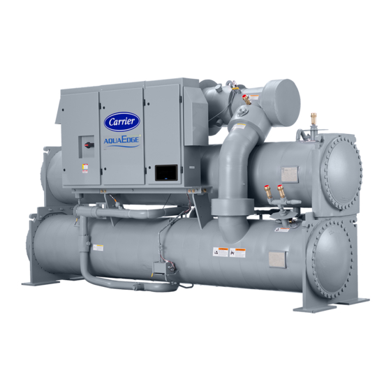
Carrier EVERGREEN 23XRV Chiller Manuals
Manuals and User Guides for Carrier EVERGREEN 23XRV Chiller. We have
7
Carrier EVERGREEN 23XRV Chiller manuals available for free PDF download: Installation Instructions Manual, Start-Up And Service Instructions, Product Data, Application Manual
Carrier EVERGREEN 23XRV Installation Instructions Manual (81 pages)
High-Efficiency Variable Speed Screw Chiller with Greenspeed Intelligence 50/60 Hz HFC-134a
Brand:
Carrier
| Category:
Chiller
| Size: 27 MB
Table of Contents
Safety Considerations
1
Installation Instructions
1
Table of Contents
2
General
2
Introduction
2
Job Data
3
Installation
3
Inspect Shipment
3
Identify Machine
3
Step 1 - Receive the Machine
3
Installation Requirements
4
Provide Machine Protection
4
Model Number Identification
4
Typical 23XRV Components (P Compressor)
5
Typical 23XRV Components (Q Compressor)
6
Typical 23XRV Components (R Compressor)
7
Sensor Locations (P Compressor)
8
Sensor Locations (Q Compressor)
9
Rig the Machine
10
Sensor Locations (R Compressor)
10
VFD Nameplate
10
Step 2 - Rig the Machine
10
Control Center Components
11
Machine Electrical Data Nameplate
12
Drive Assembly and Power Module Ratings
13
Machine Rigging Guide
14
23XRV Heat Exchanger Sizes A,B Dimensions
16
23XRV Heat Exchanger Sizes 30-57 Dimensions
17
23XRV Compressor and Motor Weights
18
23XRV Maximum Component Weights
18
23XRV Waterbox Nozzle Sizes
18
VFD (Variable Frequency Drive) Weight Table
18
23XRV Cooler Frame Size A1-A6, B1-B6 Heat Exchanger Weights
19
23XRV Additional Data for Cooler Marine Waterboxes
20
23XRV Code 30-57 Heat Exchanger Weights
20
23XRV Additional Data for Condenser Marine Waterboxes
21
23XRV Waterbox Cover Weights, Frames 3,4,5
21
23XRV Waterbox Cover Weights, Frames A/B
22
Rig Machine Components
22
Electrical Cable Routing (Unit with R Compressor)
23
Electrical Cable Routing (Unit with P Compressor)
24
Separate Cooler and Condenser
24
Step 3 - Separate Machine Components
24
Cooler/Discharge Pipe Assembly Removal (Unit with R Compressor)
25
Cooler/Discharge Pipe Assembly Removal (Unit with P Compressor)
26
Chiller End View
27
Evaporator Refrigerant Liquid Temperature Sensor on Bottom of Cooler
27
Remove the Controls/Drive Enclosure
27
VFD Refrigerant Isolation Valves
27
Control Panel Connectors
28
ICVC Communication Cables
28
Motor Terminals
28
Control Center Lifting Points
29
Control Panel Back
29
Remove the Controls/Drive Enclosure
29
Remove the Discharger Pipe Assembly from the Condenser
29
Separate the Compressor
29
Control Panel Inputs (Q, R Compressors)
30
Additional Control Panel Inputs (P Compressors)
31
Compressor Fastener Identification
32
Compressor Removal, Q and R Compressors (Unit with R Compressor)
32
Compressor Removal, P Compressor
33
Separate the Vaporizer from the Condenser
34
Oil Concentrator Removal, Q and R Compressors (Unit with R Compressor)
34
Install VFD
34
Oil Concentrator Removal, P Compressor
35
Oil Reclaim Piping (Unit with R Compressor Shown)
35
Oil Reclaim Components (Unit with R Compressor)
36
Motor Terminal Box (Q and R Compressors)
36
Motor Terminal Insulation (Q and R Compressors)
37
Motor Terminal Box (P Compressor)
37
Install Standard Isolation
38
Motor Terminal Insulation (P Compressor)
38
Install Machine Supports
38
Motor Ground Cable
39
VFD Refrigerant Connectors
39
23XRV Frame Size a Machine Footprint
40
23XRV30-57 Machine Footprint
40
23XRV Frame Size B Machine Footprint
41
Install Accessory Isolation
41
Standard Isolation
41
23XRV Accessory Spring Isolation
42
Install Spring Isolation
42
Install Water Piping to Heat Exchanger
42
Step 6 - Connect Piping
42
Piping Flow Data
43
Optional Pumpout Unit and Storage Tank
47
Optional Pumpout System Piping Schematic with Storage Tank
48
Install Vent Piping to Relief Valves
49
Optional Pumpout System Piping Schematic Without Storage Tank
49
Pumpout Unit
49
Relief Valve Arrangements
50
Grounding the Controls/Drive Enclosure
51
Installing Input Power Wiring
51
Relief Valve Locations
51
Step 7 - Make Electrical Connections
51
Typical Field Wiring Schematic (LF-2 VFD)
53
Enclosure
56
Notes to Fig.60
56
Pic III Control Component Layout
57
Connect Control Inputs/Outputs
59
Connect Starter
59
Wiring the Field Wiring Terminal Strips for STD Tier VFD
59
23XRV Controls Schematic
60
23XRV Controls Schematic Details
61
Communications Interface Board Status Leds
65
Drive Status Indicator Status Leds
65
CCN Communication Wiring for Multiple Chillers
66
23XRV with Unit-Mounted Vfd/Control Center
67
Completing the Installation
68
Checking the Installation
68
Oil Pump and Oil Heater
68
Connect Control Wiring
68
Interface
68
Carrier Comfort Network
68
Cable Manufacturers
69
Bacnet Communication Option Wiring
69
Lead-Lag Control Wiring
69
Install Field Insulation
69
UPC Open Controller
70
Network Wiring
70
BT485 Terminator Installation
71
MS/TP Wiring Recommendations
71
Open System Wiring Specifications and Recommended Vendors
72
Lead/Lag Control Wiring, Parallel Flow Application
73
Series Flow Application
74
23XRV Installation Area (P Compressor)
75
23XRV Installation Area (Q Compressor)
76
23XRV Installation Area (R Compressor)
77
Installation Start-Up Request Checklist
79
Advertisement
Carrier EVERGREEN 23XRV Installation Instructions Manual (52 pages)
High-Efficiency Variable Speed Screw Chiller with Foxfire Compression Technology and PIC III Controls 50/60 Hz HFC-134a
Brand:
Carrier
| Category:
Chiller
| Size: 12 MB
Table of Contents
Installation Instructions
1
Safety Considerations
1
General
2
Table of Contents
2
Identify Machine
2
Installation Requirements
2
Provide Machine Protection
2
Introduction
2
General
2
Job Data
2
Installation
2
Receiving the Machine
2
Inspect Shipment
2
Rigging the Machine
3
Rig Machine Assembly
3
Machine Rigging Guide
7
Rig Machine Components
11
Separate Machine Components
13
Separate Cooler and Condenser
13
From the Condenser
14
Remove the Controls/Drive Enclosure
14
Condenser
15
Remove the Discharge Pipe Assembly from the Condenser
16
Separate the Compressor from the Condenser
17
Condenser
18
Separate the Vaporizer from the
19
VFD Installation
19
Install Standard Isolation
22
Install Machine Supports
22
Install Accessory Isolation
23
Install Spring Isolation
24
Connect Piping
24
Install Water Piping to Heat Exchangers
24
Marine Waterboxes
26
Top View
27
Front View
27
Left Side View
27
Install Vent Piping to Relief Valves
30
Make Electrical Connections
30
Grounding the Controls/Drive Enclosure
31
Installing Input Power Wiring
31
Enclosure
37
Connect Control Outputs
37
Connect Control Inputs
37
Wiring the Field Wiring Terminal Strips
37
Connect Starter
37
Completing the Installation
43
Checking the Installation
43
Oil Pump and Oil Heater
43
Connect Control Wiring
43
Carrier Comfort Network Interface
43
Lead-Lag Control Wiring
44
Install Field Insulation and Lagging
44
Installation Start-Up Request
51
Checklist
51
Carrier EVERGREEN 23XRV Start-Up And Service Instructions (32 pages)
Brand:
Carrier
| Category:
Chiller
| Size: 7 MB
Table of Contents
Table of Contents
1
Safety Considerations
1
Introduction
3
Abbreviations and Explanations
3
Required Publications
3
Getting Assistance from Rockwell Automation
3
Identifying Drive Components
3
Opening the VFD Access Door
3
Drive Assembly Catalog Number
3
Components and Physical Data
4
Start-Up
7
Alternate Wire Lugs
7
Verify Installation
7
Configure the VFD
8
Commissioning the Unit
9
Check Internal Jumpers
9
Service
11
Troubleshooting the Drive
11
Chiller Alert Codes
11
Chiller Alarm Codes
11
Test Equipment Needed to Troubleshoot
11
Verifying DC Bus Capacitors Are Discharged
11
High Temperature Alarms
11
Main Control Board (Mcb) Components
14
Checking Power Modules and Motor Input with Input
14
Power off
14
Servicing the Drive
15
Removing the Drive
15
Rigging the Enclosure
17
Replacing Gateway 20-Comm-H Option Card
17
Replacing Chill Plate Fan and Internal Fan
18
Part Identification and Location
18
Appendix A - Wiring Schematics
21
Advertisement
Carrier EVERGREEN 23XRV Start-Up And Service Instructions (32 pages)
With PIC III/PIC 6 Controls Rockwell PowerFlex 755 VFD Option
Brand:
Carrier
| Category:
Chiller
| Size: 8 MB
Table of Contents
Safety Considerations
1
Table of Contents
2
Introduction
2
Abbreviations and Explanations
3
Required Publications
3
Getting Assistance from Rockwell Automation
3
Identifying Drive Components
3
Opening the VFD Access Door
3
Drive Assembly Catalog Number
3
Components and Physical Data
4
Start-Up
7
Alternate Wire Lugs
7
Verify Installation
7
Configure the VFD
8
Commissioning the Unit
9
Check Internal Jumpers
9
Service
10
Troubleshooting the Drive
10
Chiller Alert Codes
10
Chiller Alarm Codes
10
Test Equipment Needed to Troubleshoot
10
Verifying that DC Bus Capacitors Are
11
Discharged
11
High Temperature Alarms
11
Main Control Board (Mcb) Components
11
With Input Power off
14
Servicing the Drive
15
Removing the Drive
15
Rigging the Enclosure
16
Replacing the Gateway
17
Chill Plate Fan and Internal Fan Replace- Ment
18
Part Identification and Location
18
Appendix A - Wiring Schematics
21
Carrier EVERGREEN 23XRV Start-Up And Service Instructions (24 pages)
With PIC III/PIC 6 Controls Eaton LCX9000 VFD Option
Brand:
Carrier
| Category:
Chiller
| Size: 4 MB
Table of Contents
Safety Considerations
1
Table of Contents
2
Introduction
2
Abbreviations and Explanations
2
Required Publications
2
Getting Assistance from Eaton
2
Identifying Drive Components
3
Components and Application
3
Start-Up
4
Wire Lugs
4
Verify Installation
5
Configure the VFD
5
Commissioning the Unit
6
Check Configuration Jumpers
6
Service
7
Troubleshooting the Drive
7
Chiller Alert Codes
7
Chiller Alarm Codes
7
Test Equipment Needed to Troubleshoot
7
Verifying that DC Bus Capacitors Are Discharged
7
High Temperature Alarms
7
Main Control Board (Mcb) Components
7
Checking Power Modules and Motor Input
8
With Input Power off
8
Servicing the Drive
8
Removing the Drive from the Enclosure
8
Parts Identification and Location
12
Appendix A - Wiring Schematics
18
Carrier EVERGREEN 23XRV Product Data (32 pages)
High-Efficiency Variable Speed Screw Chiller with FOXFIRE Compression Technology 50/60 Hz HFC-134a 300 to 550 Nominal Tons (1055 to 1934 Nominal kW)
Brand:
Carrier
| Category:
Chiller
| Size: 4 MB
Table of Contents
Table of Contents
2
High Efficiency
2
Features/Benefits
4
Model Number Nomenclature
4
Physical Data
5
Physical Data
6
Options and Accessories
7
Dimensions
8
Performance Data
9
Electrical Data
10
Microprocessor Controls
11
Control System
11
Controls
11
Controls
14
Typical Piping and Wiring
15
Control Wiring Schematic
16
Application Data
17
Minimum Fluid Loop Volume
23
Guide Specifications
24
Carrier EVERGREEN 23XRV Application Manual (24 pages)
Counterflow
Brand:
Carrier
| Category:
Cash Counter
| Size: 0 MB
Table of Contents
Table of Contents
3
What Is the Carrier® Chillervu™ Series Counterflow Application
5
Application Library
6
Supported Chiller Hardware
6
Network and Hardware Points
7
Single Loop Plants with Coolers in Series (Series Counter Flow)
9
Start-Up and Commissioning
10
To Set up
10
To Configure Properties
11
To Start-Up the SCF System
12
Sequence of Operation
13
Lead Chiller Enable/Disable - Chiller Start Initiation
13
Chiller Staging Conditions
14
Load Balancing
14
Automatic Resets after Single Chiller Failures
15
Automatic Resets after Dual Chiller Failures
15
Rotation Method
16
Alarms
16
Optional Settings
17
Carrier® Chillervu™ 23XRV SCF System Constants
18
Communicating with the 23XRV Chillers
20
To Connect Using CCN
20
To Connect Using UPC Open Controllers
21
Document Revision History
22
Advertisement
Related Products
Carrier 23XL
Carrier 230GTN
Carrier 230GTR
Carrier 23XVE0485
Carrier 23XVE0550
Carrier 23XVE0605
Carrier 23XVE0389
Carrier 23XVE0469
Carrier 245GTR
Carrier 290GTR
Carrier Categories
Air Conditioner
Heat Pump
Furnace
Chiller
Thermostat
More Carrier Manuals
Login
Sign In
OR
Sign in with Facebook
Sign in with Google
Upload manual
Upload from disk
Upload from URL