Carrier EVERGREEN 23XRV Product Data
High-efficiency variable speed screw chiller with foxfire compression technology 50/60 hz hfc-134a 300 to 550 nominal tons (1055 to 1934 nominal kw)
Hide thumbs
Also See for EVERGREEN 23XRV:
- Installation instructions manual (81 pages) ,
- Application manual (24 pages) ,
- Start-up and service instructions (32 pages)
Table of Contents
Advertisement
S
C
EISMI
OMPLIANT
* Meets IBC 2006, ASCE-7-05, CBC 2007, and OSHPD seismic requirements.
Copyright 2010 Carrier Corporation
Product
Data
*
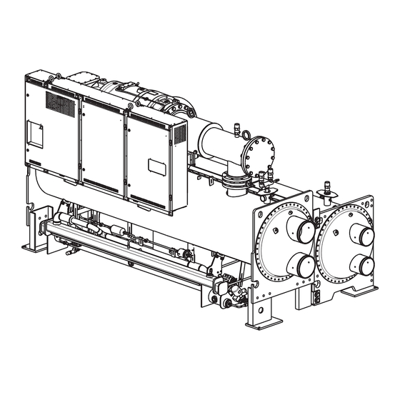
High-Efficiency Variable Speed Screw Chiller
with FOXFIRE™ Compression Technology
300 to 550 Nominal Tons (1055 to 1934 Nominal kW)
23XRV
®
2008 AHR EXPO
2008 AHR EXPO
INNOVATION
INNOVATION
AWARD
AWARD
WINNER – Green Building
EVERGREEN
50/60 Hz
HFC-134a
®
Carrier's Evergreen
®
23XRV chiller is
the world's first integrated variable
speed, water-cooled, screw chiller.
It incorporates significant break-
throughs in water-cooled chiller tech-
nology to provide excellent reliability
and achieve superior efficiencies at
true operating conditions without com-
promising the environment.
The 23XRV chiller provides:
• Variable speed, positive
displacement screw compressor.
• Air Conditioning, Heating, and
Refrigerant Institute (AHRI) certified
efficiencies to 0.33 kW/ton (AHRI
IPLV).
• Chlorine-free HFC-134a refrigerant.
• IEEE-519 compliance for harmonic
distortion.
• An ideal solution for constant and
variable flow pumping systems.
Features/Benefits
Quality design and con-
struction make the Evergreen
23XRV chillers the best
choice for modern, efficient
chilled water plants.
Product reliability
The 23XRV chiller uses proven tech-
nology from Carrier's existing line of
Evergreen chillers along with innova-
tions that increase reliability. The
23XRV compressors are designed for
extremely high reliability. The ad-
vanced tri-rotor compressor features a
balanced rotor geometry and shorter
screw lengths, resulting in vastly re-
duced compressor bearing loads and a
minimum L10 compressor bearing life
in excess of 500,000 hours when op-
erated at AHRI conditions.
Form 23XRV-3PD
®
23XRV
Advertisement
Table of Contents

Related Manuals for Carrier EVERGREEN 23XRV


Summary of Contents for Carrier EVERGREEN 23XRV
- Page 1 Product reliability The 23XRV chiller uses proven tech- nology from Carrier’s existing line of Evergreen chillers along with innova- tions that increase reliability. The 23XRV compressors are designed for extremely high reliability. The ad-...
-
Page 2: Table Of Contents
(IPLV) in an ex- tremely broad range of applications and climates. Environmental leader Carrier has long been committed to the environment and its sustainability. The Evergreen 23XRV screw chillers provide our customers with a high- efficiency, chlorine-free, long-term solution unaffected by refrigerant phase outs. - Page 3 During servicing, the “in-chiller” storage reduces refrigerant loss and eliminates time-consuming transfer procedures. As a self-contained unit, the Evergreen 23XRV chiller does not require additional remote storage systems. Optional pumpdown unit — Com- bined with the refrigerant isolation...
-
Page 4: Features/Benefits
Demand limiting — This feature lim- its the power draw of the chiller during peak loading conditions. When incor- porated into the Carrier Comfort Network ® building automation system, a red line command holds chillers at their present capacity and prevents any other chillers from starting. -
Page 5: Physical Data
Physical data Total MOTOR Compressor SIZE Weight Weight (lb) P,Q,R,S, 4866 T,U,V COMPONENT Isolation Valves Suction Elbow Discharge Elbow/Muffler Control Center/VFD Vaporizer and Oil Sump Economizer LEGEND VFD — Variable Frequency Drive Dry Rigging NUMBER Weight OF TUBES (lb)* CODE Cooler Cond. -
Page 6: Physical Data
Physical data (cont) ADDITIONAL WEIGHTS FOR 23XRV MARINE WATERBOXES* NUMBER FRAME Cooler PASSES Rigging Wgt Liquid Wgt 1 and 3 1 and 3 1888 1 and 3 2445 1223 NUMBER FRAME Cooler PASSES Rigging Wgt Liquid Wgt 1 and 3 1 and 3 2162 1552... -
Page 7: Options And Accessories
Zinc Anodes 100K AIC (Amp Interrupt Capacity) High Interrupt Circuit Breaker with Shunt Trip Analog Voltmeter and Ammeter with 3 Phase Selector Switch BACnet*** Communications LonWorks††† Carrier Translator Sensor Package Refrigerant Isolation Valves Separate Storage Tank and Pumpout Unit Shipped Factory Charged with Refrigerant... -
Page 8: Dimensions
Dimensions TUBE REMOVAL SPACE FOR EITHER END SIZES 30-32, 40-42 50-52 14’-3” (4343 mm) SIZES 35-37, 45-47 55-57 14’-0” (4267 mm) SERVICE AREA 23XRV DIMENSIONS (NOZZLE-IN-HEAD WATERBOX) HEAT EXCHANGER 1 Pass SIZE ft-in. 30 to 32 14- 3 35 to 37 15-11 40 to 42 14- 9... -
Page 9: Performance Data
Performance data FRAME SIZE 1-Pass 23XRV HEAT EXCHANGER MIN/MAX FLOW RATES* COOLER 1 PASS Frame Size 2,444 2,933 3,422 2,444 2,933 3,422 3,959 1112 4,448 1222 4,888 3,959 1112 4,448 1222 4,888 1316 5,267 1482 5,927 1586 6,343 1316 5,267 1482 5,927 1586... -
Page 10: Electrical Data
Electrical data FRAME SIZE *Maximum limits only. Additional application limits apply that will reduce these ampacities. ITEM Controls, Oil Pump And Heater Circuit† Oil Pump Oil Sump Heater Oil Vaporizer Heater Circuit† Oil Vaporizer Heater *Factory wired to VFD. †Minimum circuit ampacity of 15 amps. VFD FRAME SIZES MAX INPUT CURRENT* AUXILIARY RATINGS*... -
Page 11: Controls
Control system The microprocessor control on each Carrier chiller is factory-mounted, factory-wired, and factory-tested to ensure machine protection and efficient capacity control. In addition, the program logic ensures proper starting, stopping, and recycling of the chiller and provides a com- munication link to the Carrier Comfort Network®... - Page 12 Controls (cont) CONTROL PANEL DISPLAY (Front View) ICVC ENGLISH DISPLAY IN SI UNITS CONTROL PANEL DISPLAY (Front View) ICVC CHINESE DISPLAY IN METRIC UNITS...
- Page 13 a23-1649...
-
Page 14: Controls
Controls (cont) CONTROL SEQUENCE MACHINE SAFETIES, EVAPORATOR PUMP CONDENSER WATER PUMP WA TER FLOWS CHILLED WATER TEMP, TOWER FAN CONTROL OIL PUMP OIL PRESSURE VERIFIED VDF FAULT TEST COMPRESSOR, PHASE REVERSAL, COMPRESSOR AND SERVICE ONTIME COMPRESSOR RAMP VDF TO TARGET SPEED 15-MINUT E START-TO-START TIMER... -
Page 15: Typical Piping And Wiring
Certified field wiring and dimensional diagrams are available on request. 2. All wiring must comply with applicable codes. 3. Refer to Carrier System Design Manual for details regarding piping techniques. 4. Wiring not shown for optional devices such as: • remote start/stop •... -
Page 16: Control Wiring Schematic
Control wiring schematic LEGEND CCM — Chiller Control Module CCN — Carrier Comfort Network® ICVC — International Chiller Visual Controller GND — Ground 23XRV COMPONENT ARRANGEMENT... -
Page 17: Application Data
Application data ACCESSORY SOLEPLATE 0’-01/2” [13mm] TYP. *See detail on page 18. 23XRV HEAT EXCHANGER SIZE 30-32 12-10 35-37 14- 7 40-42 12-10 45-47 14- 7 50-52 12-10 55-57 14- 7 23XRV MACHINE FOOTPRINT VESSELS VESSELS COND. TYP. 0’-3” [76.2mm] COOLER DIMENSIONS (ft-in.) a23-1650... - Page 18 Application data (cont) 23XRV ISOLATION WITH ACCESSORY SOLEPLATE PACKAGE TYPICAL ISOLATION NOTES: 1. Dimensions in ( ) are in millimeters. 2. Accessory soleplate package includes 4 soleplates, 16 jacking screws and leveling pads. Requires isolation package. 3. Jacking screws to be removed after grout has set. 4.
- Page 19 DISCHARGE END DISCHARGE END NOZZLE ARRANGEMENT CODES FOR ALL 23XRV NOZZLE-IN-HEAD WATERBOXES COOLER WATERBOXES PASS *Refer to certified drawings. 23XRV NOZZLE ARRANGEMENTS NOZZLE-IN-HEAD WATERBOXES FRAME 3 FRAMES 4 AND 5 PASS Arrangement Code* SUCTION END SUCTION END CONDENSER WATERBOXES Arrangement Code*...
- Page 20 Application data (cont) DISCHARGE END COOLER WATERBOXES PASS DISCHARGE END COOLER WATERBOXES PASS 23XRV NOZZLE ARRANGEMENTS (cont) MARINE WATERBOXES FRAME 3 NOZZLE ARRANGEMENT CODES PASS Arrangement Code FRAMES 4, AND 5 NOZZLE ARRANGEMENT CODES PASS Arrangement Code SUCTION END CONDENSER WATERBOXES Arrangement Code —...
- Page 21 23XRV WATERBOX NOZZLE SIZES (Nozzle-In-Head and Marine Waterboxes FRAME PRESSURE SIZE psig (kPa) 150/300 (1034/2068) 150/300 (1034/2068) 150/300 (1034/2068) FRAME LOCATION MUFFLER COOLER CONDENSER OPTIONAL STORAGE TANK * Coolers without optional isolation require 2 relief valves. NOTE: All valves relieve at 185 psig (1275 kPa). WITH OPTIONAL ISOLATION OF DISCHARGE AND COOLER WITH OPTIONAL ISOLATION NOMINAL PIPE SIZE (in.)
- Page 22 HEAT EXCHANGER COOLER CONDENSER Carrier further recommends that an oxygen sensor be installed to protect personnel. Sensor should be able to sense the depletion or displacement of oxygen in the ma- chine room below 19.5% volume oxygen per ASHRAE 15, latest edition.
-
Page 23: Minimum Fluid Loop Volume
Insulation 23XRV MINIMUM FIELD-INSTALLED INSULATION REQUIREMENTS COMPONENT SIZE 30-32 35-37 40-42 Cooler 45-47 50-52 55-57 Misc. Liquid Lines All Sizes Economizer All Sizes Compressor Motor All Sizes Factory insulation — Thermal insulation is factory- provided to the following areas: • Cooler (not including waterbox) •... -
Page 24: Guide Specifications
Variable Speed Screw Chiller HVAC Guide Specifications Size Range: 300 to 550 Tons (1055 to 1934 kW) Nominal Carrier Model Number: 23XRV Part 1 — General 1.01 SYSTEM DESCRIPTION A. Microprocessor-controlled liquid chiller shall use a semi-hermetic screw compressor using refrigerant HFC-134a only. - Page 25 D. Unit shall be shipped with firmly attached labels that indicate name of manufacturer, chiller model num- ber, chiller serial number, and refrigerant used. E. If the unit is to be exported, the manufacturer shall provide sufficient protection against sea water corro- sion, making the unit suitable for shipment in a standard open top ocean shipping container.
- Page 26 Guide specifications (cont) equipment to dissipate the motor heat as per the following formula: Btuh = (FLkW motor) (0.05) (3413) Btuh = (FLkW motor) (171) and, alternately Tons = Btuh/12,000 The additional piping, valves, air-handling equipment, insulation, changes, ductwork, and coordination with other trades shall be the responsibility of the mechan- ical contractor.
- Page 27 input terminals as the point of common cou- pling (PCC). b. The VFD full load efficiency shall meet or exceed 97% at 100% VFD rated ampacity. c. Active rectifier shall regulate unity displace- ment power factor to 0.99 or higher. d.
- Page 28 Guide specifications (cont) liquid refrigerant to a reduced temperature, thereby increasing efficiency. F. Refrigerant Flow Control: To improve part load efficiency, liquid refrigerant shall be metered from the condenser to the cooler using a float-type metering valve to maintain the proper liquid level of refrigerant in the heat exchangers under both full and part load operating conditions.
- Page 29 displayed informing the operator that the chiller is operating in ramp loading mode. l. Chilled Water Reset: The control center shall allow reset of the chilled water temperature set point based on any one of the following criteria: 1) Chilled water reset based on an external 4 to 20 mA signal.
- Page 30 The chiller control system shall have the ability to interface and communicate directly to the building control using a LON based system. The LonWorks Carrier Translator shall output data in standard LON profiles. The chiller shall ship from the factory fully charged with R-134a refrigerant and oil.
- Page 31 11. Cooler and Condenser Tubes: Contact a local Carrier Representative for other tube offerings. 12. Cooler and Condenser Passes: Unit manufacturer shall provide the cooler and/ or condenser with 1, 2 or 3 pass configuration on the water side. 13. Nozzle-In-Head, 300 psig (2068 kPa):...
- Page 32 Carrier Corporation • Syracuse, New York 13221 5-10 Manufacturer reserves the right to discontinue, or change at any time, specifications or designs without notice and without incurring obligations. Section 9 Pg 32 Catalog No. 04-52230002-01 Printed in U.S.A. Form 23XRV-3PD...
Need help?
Do you have a question about the EVERGREEN 23XRV and is the answer not in the manual?
Questions and answers