Sign In
Upload
Manuals
Brands
BMS Manuals
Control Panel
8714395001
BMS 8714395001 Manuals
Manuals and User Guides for BMS 8714395001. We have
1
BMS 8714395001 manual available for free PDF download: Installation & Operation Manual
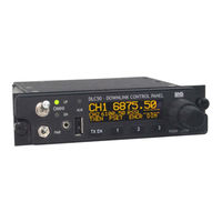
BMS 8714395001 Installation & Operation Manual (44 pages)
DOWNLINK CONTROL PANEL
Brand:
BMS
| Category:
Control Panel
| Size: 0.87 MB
Table of Contents
Table of Contents
5
1 Introduction
7
Figure 1. DLC50 Downlink Control Panel
7
Figure 2. Generic DLC50 Microwave System
8
Table 1. DLC50 Models
8
Figure 3. DLC50 Control Panel Components, Front View
9
Figure 4. DLC50 Control Panel Components, Rear View
9
Table 2. DLC50 Front and Rear Switches and Ports Descriptions
9
Receiver Serial Port (COM3)
11
Remote Serial Port (COM0)
11
Transmitter Serial Port (COM2)
11
2 Installation
12
Installing the DLC50 (Replacing an HCP50-II)
12
Installing the DLC50 (New Installation)
12
Figure 5. Panel Mounting Dimensions Recommended for the DLC50 (Per MS25212C)
12
Figure 6. DLC50 to HCP50 Harness (CCII/HCII) Adapter (BMS# 7314395012)
13
Figure 7. DLC50 to HCP50 Harness (Ctxx40Arinc) Adapter (BMS# 7314395011)
13
Figure 8. Basic Connection Diagram
14
Figure 9. Typical Installation
14
Figure 10. DLC50 Chassis Dimensions
15
Connectors and Pin-Outs
16
Power Cable Connector
16
DB25-5 Connector
16
Figure 11. DLC50 Power Connector
16
Figure 12. DB25-5 Connector
16
Table 3. Power Connector Pin-Out (PT02E-12-4P)
16
Table 4. DB25-S Connector Pin-Out
16
TAA-101 Cable Connector Pin-Out
17
DC Power and DC Power Control Connections
17
Transmitter Connections
17
Figure 13. DLC50 to TAA-101 Antenna Actuator Connector
17
Table 5. TAA-101 Control Connector Pin-Out (PT02E-10-98S)
17
RF Power Amplifier Connections
18
Receiver Connections
18
Remote Connections
18
Figure 14. Remote Primary to Secondary "Null-Modem" Connection
18
Actuator Connections
19
Relay Connections
19
Figure 15. Front Panel 2.5Mm Serial Cable
19
External Dimmer Connections
20
3 Displays, Controls and Menu Navigation
21
Display and Leds
21
Figure 16. Normal Display
21
Figure 17. Display Showing TXEN Status (Transmitter On)
21
Keypad
22
Rotary Encoder
22
Menu Navigation
23
4 Setup and Configuration
24
Language Setup
24
RX Serial Setup
24
TX Serial Setup
24
Remote Serial Setup
24
USB Flash Functions
25
Example: Loading a TX Channel Plan from a USB Thumb Drive
26
External Relay Setup
26
Presets Setup
27
Simple UI Setup
27
Figure 18. Diplexer Subband Switching Configuration Example
27
Figure 19. Multiple Subband Filter Array Configuration Example
27
Soft-Key Setup
28
Key-Timer Setup
28
System Functions
28
5 Operation
29
Selecting a TX or RX Channel
29
Selecting a TX or RX Frequency
29
Recalling a TX or RX Preset
29
Recalling, Saving and Erasing a DLC50 Preset
29
Setting Encryption or Decryption
30
Setting RF Power Level
30
Changing the RX Meter Type
30
Dimming the Panel and Display
30
6 Specifications
32
7 Preventive Maintenance
34
8 Troubleshooting
35
9 Repair Service/Warranty Information
36
Figure 20. BMS Product Label
36
Customer Service Contact Information
37
10 Glossary
38
11 Index
40
12 Appendix
41
Advertisement
Advertisement
Related Products
BMS 8714395000
BMS 8714395002
BMS 8714395003
BMS BMS EcoCam 8
BMS Ecocam 8 MkII
BMS DLC50
BMS DLC50-A
BMS DLC50-AN
BMS DLC50-N
BMS Categories
Microscope
Test Equipment
Transmitter
Measuring Instruments
Motorcycle
More BMS Manuals
Login
Sign In
OR
Sign in with Facebook
Sign in with Google
Upload manual
Upload from disk
Upload from URL