Sign In
Upload
Manuals
Brands
Beckhoff Manuals
Control Unit
BK5200
Beckhoff BK5200 Manuals
Manuals and User Guides for Beckhoff BK5200. We have
2
Beckhoff BK5200 manuals available for free PDF download: Documentation, Technical Documentation Manual
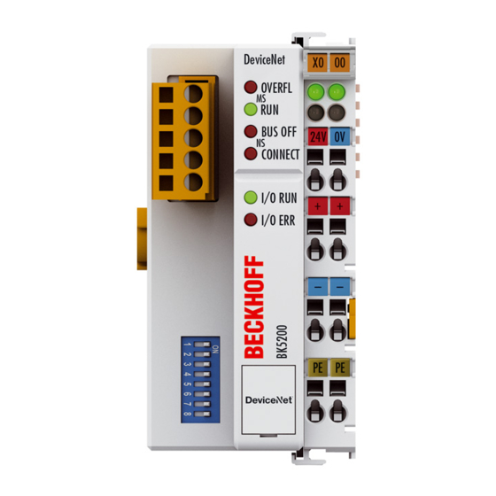
Beckhoff BK5200 Documentation (47 pages)
Bus Coupler for DeviceNet
Brand:
Beckhoff
| Category:
Industrial Equipment
| Size: 3.65 MB
Table of Contents
Table of Contents
3
1 Foreword
5
Notes on the Documentation
5
Safety Instructions
6
Documentation Issue Status
7
2 Product Overview
8
BK5200 - Introduction
8
Fig. 1 BK5200 - Bus Coupler for Devicenet
8
BK5250 - Introduction
9
Fig. 2 BK5250 - Compact Bus Coupler for Devicenet
9
LC5200 - Introduction
10
Fig. 3 LC5200 - Low-Cost Bus Coupler for Devicenet
10
Technical Data
11
3 Basic Function Principles
12
The Beckhoff Bus Terminal System
12
Principle of the Bus Terminal
14
Fig. 4 Principle of the Bus Terminal
14
Devicenet
15
Devicenet Introduction
15
Fig. 5 Devicenet
15
Fig. 6 Example of Devicenet in Use
15
Data Exchange
16
Fig. 7 Data Exchange
17
Vendor ID
18
Devicenet Group
18
Fig. 8 Overview of the Identifiers Used
18
4 Mounting and Wiring
19
Instructions for ESD Protection
19
Dimensions
19
Fig. 9 Spring Contacts of the Beckhoff I/O Components
19
Installation on Mounting Rails
20
Fig. 10 Dimensions
20
Power Supply, Potential Groups
22
Fig. 11 BK5200, BK5210, BK5250 - Potential Groups
23
Electrical Isolation
24
Fig. 12 Potential Levels of the BK5200 and BK5210
24
Devicenet Connection - Pin Assignment
25
Fig. 13 Devicenet Connection - Pin Assignment
25
Fig. 14 LC5200 - Connection Diagram
25
Bus Cable Lengths and Pin Assignment
26
Fig. 15 Devicenet - Baud Rate and Bus Length
26
Fig. 16 Layout of the ZB5200 Can/Devicenet Cable
26
Fig. 17 Cable Assignment
27
ATEX - Special Conditions (Standard Temperature Range)
28
ATEX - Special Conditions (Extended Temperature Range)
29
Continuative Documentation for ATEX and Iecex
30
5 Parameterization and Commissioning
31
Start-Up Behaviour of the Bus Coupler
31
Peripheral Data in the Process Image
31
Fig. 18 Start-Up Behaviour of the Bus Coupler
31
Fig. 19 Output Data in the Bus Coupler
32
Fig. 20 Input Data in the Bus Coupler
33
Fig. 21 Process Image in the BK5200 and in the PLC (Scanner)
33
Configuration of the Bus Coupler
35
Fig. 22 BK5200 - Configuration
35
Fig. 23 DIP Switch
35
Diagnostic Leds
37
LED Displays
38
LED Function Matrix
39
6 Appendix
41
Composition of a Process Image in the Bus Coupler
41
Fig. 24 Process Image in the Bus Coupler - Output Data
43
Fig. 25 Process Image in the Bus Coupler - Input Data
43
Support and Service
44
List of Figures
45
Advertisement
Beckhoff BK5200 Technical Documentation Manual (25 pages)
DEVICENET Coupler
Brand:
Beckhoff
| Category:
Control Unit
| Size: 1.33 MB
Table of Contents
Table of Contents
2
1 Basic Information
3
The Beckhoff Bus Terminal System
3
The Interfaces
5
Power Supply
5
Power Supply to the Power Contacts
5
Power Contacts
5
Fieldbus Connection
6
Configuration Interface
6
K-Bus Contacts
6
Supply Isolation
6
The Operating Modes of the Bus Coupler
7
Mechanical Construction
8
The Peripheral Data in the Process Image
10
Starting Operation and Diagnostics
12
2 Bk52X0 Devicenet
14
Introducing the System
14
Configuring the Bus Coupler
16
Pin-Out
17
Exchanging Data
17
Light-Emitting Diodes
18
Vendor ID
19
Devicenet Group
19
Maximum Cable Length
20
Potential Isolation
21
Sample Arrangement of a Process Image in the Bus Coupler
22
Representation of Analog Signals in the Process Image
24
Advertisement
Related Products
Beckhoff B310
Beckhoff BK5210
Beckhoff BK5250
Beckhoff BK8000
Beckhoff BK75 series
Beckhoff SERCOSCoupler BK7500
Beckhoff BK35 0 Series
Beckhoff BK3120
Beckhoff BK9105
Beckhoff BK11 0 Series
Beckhoff Categories
Touch terminals
Industrial PC
Control Unit
Touch Panel
Power Supply
More Beckhoff Manuals
Login
Sign In
OR
Sign in with Facebook
Sign in with Google
Upload manual
Upload from disk
Upload from URL