Sign In
Upload
Manuals
Brands
Ametek Manuals
Measuring Instruments
AN-3200
Ametek AN-3200 Manuals
Manuals and User Guides for Ametek AN-3200. We have
1
Ametek AN-3200 manual available for free PDF download: Installation And Configuration Manual
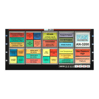
Ametek AN-3200 Installation And Configuration Manual (161 pages)
Annunciator system
Brand:
Ametek
| Category:
Security System
| Size: 5.07 MB
Table of Contents
Table of Contents
5
Scope
9
Product Overview
11
Safety
11
Construction
13
System Front View
13
System Rear View
13
Module Cell
14
Cell Assembly
14
Module Cell Configurations
15
Annunciator Windows
15
Annunciator Model Code Definition
16
System Configuration and Set-Up
19
Hardware Configuration
20
I/O Modules
20
Field Contact Type
20
Field Contact Voltage (Fcv)
21
Optional Repeat Relays
21
I/O Module Configuration
22
I/O Address
23
Display Module
24
Common Service Modules
25
Common Service Pushbutton Assemblies
26
Communication Modules
26
Serial/Ethernet Communication Module
27
Carrier Card
28
Communications Card
28
Ground Fault Detector Module
29
Power Supply Modules
29
Field Contact Voltage Supply Modules
30
Irig-B Module
30
Installation
31
Mounting
31
Panel Mounting(Option PM, PC)
31
19" Rack Mounting (Option RK)
33
Nema Enclosure (Option N4, N4PB)
34
Surface (Wall) Mounting (Option S)
35
Weather Tight NEMA Front Cover (Option NCB, NCT)
37
External Power Supply Mounting
41
120/230Vac Power Supply
41
125Vdc Power Supply
41
Wiring
42
Input Wiring
42
Common Field Contact Voltage
42
Isolated Field Contact Voltage
43
Input / Relay Wiring for Full Size Windows (Using One I/O Card)
44
Input/Relay Wiring for Half Size Windows (Using One I/O Card)
45
Input/Relay Wiring for Half Size Windows (Using One I/O Card)
46
Input Wiring with Half Size Windows ( Using Two I/O Cards )
47
Repeat Relay Wiring for Half Size Windows (Using Two I/O Cards)
48
Input/Relay Wiring for Quad Size Windows (Using Two I/O Cards)
50
Common Service Cell Wiring (with Integral Pushbuttons)
51
Common Service Wiring (with I/O Modules)
52
Onnecting Ower
53
120/230 Vac & 125Vdc Input Power
53
Field Contact Voltage
53
Power Requirements
54
External Ac Supply
54
Integral Ac Supply
54
Integral Power Supply
55
125Vdc or 120/230 Vac Integral Power Supply
56
125Vdc or 120/230Vac Integral Field Contact Voltage (Fcv) Supply
57
120/230 Vac and 125 VDC Integral Power Supply Wiring
58
24Vdc Integral Power / Fcv Supply
59
48Vdc Integral Power Supply
60
And 48 VDC Integral Ower Upply Iring
61
External Power Supply
62
VDC External Power Supply Wiring
62
120/230 Vac External Power Supply Wiring
64
Software Configuration
65
Application
65
Software Installation
65
Software Configuration Instructions
66
Reviewing or Editing the Factory Configuration
66
Creating a New Configuration
67
Software Configuration Menus
68
Main Menu Overview
68
File Menu
68
Options Menu
68
View Menu
68
Connections Menu
68
Help Menu
68
File
69
Options
71
View Configuration (Text)
72
Configuration Wizard
77
System
78
Input Configuration
81
Alarm Numbering
81
Switch Inputs
90
External Switch Function Settings
90
Test Configuration
91
Other System Configurations
91
Ascii
92
Settings for Serial Port (Option Spt)
92
Modbus
94
Settings for Ethernet (Option Eth)
94
Settings for Serial Port (Option Spt)
95
Common Modbus Settings
96
Dnp3.0
98
Settings for Ethernet (Option Eth)
98
Settings for Serial Port (Option Spt)
99
Common Dnp Configuration Settings
100
System Specifications
103
Inputs
103
Display
103
Repeat Relay Outputs
104
Alarm Sequence
105
Controls
106
System Relays
106
Audible Devices
106
Communications
107
Time Stamped Alarms
107
Indicators
108
Power Requirements
108
Mechanical
109
Connections / Terminations
109
Environment
109
Electrical
110
Certifications
110
Servicing
111
Module Removal
111
Esd
112
Appendix A
113
Appendix A Perational Equences
113
Aonl
113
Afnl
114
Frm
114
Asfr
115
Asfrm
115
Tfs
115
Tfsfrm
116
Tfsm
116
Arr
116
Frr
116
Vsrr
117
Appendix B
118
Appendix B Modbus Data Formats
118
Point Mode
119
An3135 Mode
120
Event Data
121
Modbus Addresses
122
Default Values
122
Appendix C
123
Dnp Data Formats
123
Device Profile Document
123
Implementation Table
124
Pushbutton Controls
125
Series 90B Data Ap
126
Binary Inputs
126
Binary Input Change with Time (SER Option)
126
Appendix C
123
Appendix D
128
Appendix D Ascii Output Format
128
Appendix E
129
Appendix E
129
Web Option
129
Series 90B Home Page
131
Web Pb Control
131
Home Page Editable Fields
132
Station ID
132
Device ID
132
Who to Contact
132
Customer
132
Web Browser Navigation
133
Active Alarms Page
134
Event Log Page
135
Event Descriptor
136
Download File (. Csv )
137
Erase the Log (Only for Administrators)
137
Print Events
137
Maximum Events to Retrieve
137
Event Sorting and Filtering
138
Event Sorting
138
Filter Events by
138
Date & Time Filter
138
Descriptor Filter
139
Point Number(S) Filter
139
Access Control Configuration
140
User Account Can
140
Admin Account Can
140
Trusted Ips/Hostnames
142
Ports
142
Https
142
Ntp Option
143
Email Option
144
Alarm Inputs
145
Save and Restore Configuration
146
Firmware Configuration
147
Color Selection
149
Documentation
150
Logon as User
150
Appendix F
152
Appendix F Window Assembly Details
152
Window Legends
152
Window Colors
152
Window Assembly
153
Appendix G Browser Compatibility
155
Appendix H Notes on Saving the Event File as .Csv
157
Appendix I Alternate Method for Ethernet Config
159
Appendix J
160
Appendix J Telephone / Fax Number List
160
Procedures for Factory Repair and Return
161
Arranty
161
Advertisement
Advertisement
Related Products
Ametek JOFRA ATC-140
Ametek JOFRA ATC-250
Ametek JOFRA ATC-156
Ametek JOFRA ATC-125 A
Ametek JOFRA ATC-157 A
Ametek JOFRA ATC-140 B
Ametek JOFRA ATC-157 B
Ametek JOFRA ATC-320 B
Ametek ASR900
Ametek AMEVision 3050 Series
Ametek Categories
Measuring Instruments
Test Equipment
Power Supply
Controller
Laboratory Equipment
More Ametek Manuals
Login
Sign In
OR
Sign in with Facebook
Sign in with Google
Upload manual
Upload from disk
Upload from URL