Sign In
Upload
Manuals
Brands
Allied Telesis Manuals
Switch
x600-24Ts-POE
Allied Telesis x600-24Ts-POE Manuals
Manuals and User Guides for Allied Telesis x600-24Ts-POE. We have
2
Allied Telesis x600-24Ts-POE manuals available for free PDF download: Installation Manual
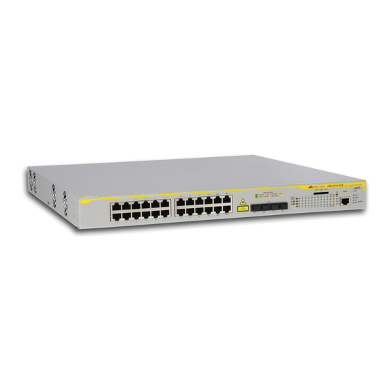
Allied Telesis x600-24Ts-POE Installation Manual (112 pages)
x600 Series Layer 3 Gigabit Ethernet Switches
Brand:
Allied Telesis
| Category:
Switch
| Size: 9 MB
Table of Contents
Installation Guide
1
Electrical Safety and Emissions Standards
3
This Guide Contains the Installation Instructions for the X600 Series Layer
3
Translated Safety Statements
4
Table of Contents
5
Preface
11
Product Documentation
12
Starting a Management Session
13
Safety Symbols Used in this Document
14
Table 1. Safety Symbols
14
Where to Find Web-Based Guides
15
Contacting Allied Telesis
16
Online Support
16
Email and Telephone Support
16
Returning Products
16
Sales or Corporate Information
16
Warranty
16
Management Software Updates
16
Chapter 1: Overview
17
Introduction
18
Switch Descriptions
19
X600-24Ts Switch
19
Figure 1. X600-24Ts Switch
19
X600-24Ts/Xp Switch
20
Figure 2. X600-24Ts/Xp Switch
20
X600-48Ts Switch
21
Figure 3. X600-48Ts Switch
21
X600-48Ts/Xp Switch
22
Figure 4. X600-48Ts/Xp Switch
22
X600-24Ts-POE
23
Figure 5. X600-24Ts-POE Switch
23
X600-24Ts-POE
24
Figure 6. X600-24Ts-POE+ Switch
24
10/100/1000Base-T Ports
25
Connector Type
25
Speed
25
Duplex Mode
25
Maximum Distance
25
Cable Type
26
Auto-MDI/MDI-X
26
Port Pinouts
26
SFP Transceiver Slots
27
Figure 7. SFP Transceiver
27
XFP Transceiver Slots
28
Figure 8. XFP Transceiver
28
Combo Ports
29
Table 2. 10/100/1000Base-T Ports Matched with SFP Slots
29
SD Card Slot
30
Figure 9. SD Card Slot
30
Figure 10. SD Card
30
Port Leds
31
10/100/1000 Base-T Leds
31
Figure 11. Port Leds on X600-24Ts and X600-24Ts/Xp Switches
31
Figure 12. Port Leds on X600-48Ts and X600-48Ts/Xp Switches
31
Figure 13. Port Leds on X600-24Ts-POE and X600-24Ts-POE+ Switches
32
Table 3. Base-T LED Descriptions
32
SFP Leds
33
Figure 14. SFP Leds - X600-24 Port Switch
33
XFP Transceiver Slot Leds
34
Figure 15. SFP Leds - X600-48 Port Switch
34
Figure 16. XFP Leds on X600-24Ts/Xp and X600-48Ts/Xp Switches
34
Table 4. SFP Slot LED Descriptions
34
Table 5. XFP Slot LED
35
System STATUS Leds
36
Figure 17. System STATUS Leds
36
Table 6. System STATUS Leds
36
STACK Leds
37
Figure 18. Non Poe Switch STACK Leds
37
Figure 19. X600-24Ts-POE and X600-24Ts-POE+ STACK Leds
37
Table 7. STACK Leds
38
Secure Digital (SD) LED
39
Figure 20. Secure Digital Slot LED
39
Table 8. Secure Digital LED
39
Terminal Port
40
Power over Ethernet (Poe and Poe+)
41
Poe
42
Enhanced Poe
42
Differences between Poe, Poe+ and Enhanced Poe
43
Power Classes
44
Power Capacity
44
Table 9. Class Vs. Power Levels
44
Implementation
45
Redundant Power Supplies
46
Figure 21. AT-RPS3204 Redundant Power Supply Unit
46
AT-LBM (Loop Back) Module
47
Figure 22. AT-LBM Module Installed in X600-48Ts/Xp Expansion Slot
47
VCS Stacking Module
48
Figure 23. VCS Stacking Module (AT-Stackxg)
48
AC Power Connector
49
Chapter 2: Virtual Chassis Stacking
51
Vcstack TM Introduction
52
Features of Vcstacking
52
The Physical Stack
52
Vcstack Introduction
52
Figure 24. Back-To-Back Topology (X600 Switches)
53
Resiliency Link
54
Vcstack Recovery States
54
Figure 25. VCS Ring Topology Using X600 Switches
54
Table 10. State Change Table
55
Resiliency Link Configurations Via Switch Ports
56
Figure 26. Resiliency Link Connecting to Switch Ports over the Resiliencylink VLAN
56
Figure 27. Resiliency Link Connecting to Switch Ports over the Resiliencylink VLAN Using a Network Hub
56
Resilient Stacked Topology
57
Stack Formation
58
The Role of the Stack Master
58
Figure 28. STACK and STATUS Leds
60
Table 11. Stacking LED Functions
60
Stack Member Failure and Recovery
61
VCS Failure Recovery
62
Stack Maintenance
63
Chapter 3: Installing the Hardware
65
Reviewing Safety Precautions
66
Unpacking a Switch
69
Installing the Power Cord Retaining Clip
70
Figure 29. Power Cord Retaining Clip
70
Figure 30. Inserting the Retaining Clip into the Retaining Bracket
70
Installing the Switches in an Equipment Rack
71
Figure 31. Removing the Feet
71
Figure 32. Attaching Rack-Mount Brackets
71
Figure 33. Mounting the Switch in a Rack
72
Resetting the Switch
73
Figure 34. Resetting the Switch
73
VC Stacking Module Installation
74
Overview
74
Preparation
74
Figure 35. VC Stacking (AT-Stackxg) Module
74
Installing the AT-Stackxg Module
75
Figure 36. Removing the Blank Panel from the Expansion Slot
75
Figure 37. Installing the AT-Stackxg Stacking Module
76
Figure 38. Securing the AT-Stackxg Stacking Module
76
Figure 39. Removing the Plastic Protector
77
Chapter 4: Cabling the Network Ports
79
Twisted Pair and Fiber Optic Specifications
80
Twisted Pair Cable Specifications
80
Table 12. Twisted Pair Cabling and Distances
80
SFP/XFP Transceiver Specifications
81
Installing SFP/XFP Transceivers
82
Installing an SFP Transceiver
82
Figure 40. Removing a Dust Plug from an SFP Slot
82
Figure 41. Installing an SFP Transceiver
83
Figure 42. Positioning Handles on the X600-24Ts and X600-24Ts/Xp Switches
83
Figure 43. Positioning SFP Handles on the X600-48Ts and X600-48Ts/Xp Switches
84
Installing an XFP Transceiver
85
Figure 44. Removing an XFP Dust Plug
85
Figure 45. Installing an XFP Transceiver
85
Cabling the 10/100/1000Base-T and Fiber Optic Ports
87
Powering on a Switch
88
Figure 46. Power Cord Retaining Clip in the up Position
88
Figure 47. Connecting the AC Power Cord
88
Figure 48. Connecting the Management Cable to the RJ-45 Terminal Port on the Switch
89
Starting a Local Management Session
89
Warranty Registration
91
Chapter 5: Troubleshooting
93
Power LED Is off
94
Twisted Pair Port Link LED Is off
95
SFP or XFP LED Is off
96
Transceiver Is Installed but the Status Is "Not Present
97
System Fault LED Is Blinking
98
System Fault LED Is Steadily on
99
Cannot Establish a Local (Out-Of-Band) Management Session
100
Switch Functions Intermittently
101
Issues with Virtual Stacking Chassis Configuration
102
Appendix A: Technical Specifications
103
Physical Specifications
103
Environmental Specifications
104
Power Specifications
104
Certifications
105
RJ-45 Twisted Pair Port Pinouts
106
Figure 49. RJ-45 Connector and Port Pin Layout
106
Table 13. MDI Pin Signals - 10 or 100 Mbps
106
Table 14. MDI-X Pin Signals - 10 or 100 Mbps
106
Table 15. Pin Signals - 1000 Mbps
107
RJ-45 Style Serial Terminal Port Pinouts
108
AT-RPS3104 17-Pin Connector Pinouts
108
Figure 50. AT-RPS3104 17-Pin Connector Layout
108
Table 16. RJ-45 Style Serial Terminal Port Pin Signals
108
Table 17. AT-RPS3104 17-Pin Connector Pinout Definitions
109
Pin Definition
109
AT-RPS3204 21-Pin D-Combo Port and Connector Pinouts
110
Figure 51. AT-RPS3204 21-Pin D-Combo Connector and Port Pin Layout
110
Table 18. AT-RPS3204 21-Pin Connector Pinout Definitions
110
Advertisement
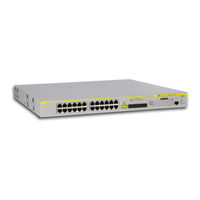
Allied Telesis x600-24Ts-POE Installation Manual (110 pages)
x600 Series Layer 3 Gigabit Ethernet Switches
Brand:
Allied Telesis
| Category:
Switch
| Size: 7 MB
Table of Contents
Installation Guide
1
Electrical Safety and Emissions Standards
3
Translated Safety Statements
4
Table of Contents
5
List of Figures
9
Product Documentation
14
Starting a Management Session
15
Safety Symbols Used in this Document
16
Table 1. Safety Symbols
16
Where to Find Web-Based Guides
17
Contacting Allied Telesis
18
Online Support
18
Email and Telephone Support
18
Warranty
18
Returning Products
18
Sales or Corporate Information
18
Management Software Updates
18
Chapter 1: Overview
19
Introduction
20
Switch Descriptions
21
X600-24Ts Switch
21
Figure 1. X600-24Ts Switch
21
X600-24Ts/Xp Switch
22
Figure 2. X600-24Ts/Xp Switch
22
X600-48Ts Switch
23
Figure 3. X600-48Ts Switch
23
X600-48Ts/Xp Switch
24
Figure 4. X600-48Ts/Xp Switch
24
X600-24TS-POE
25
Figure 5. X600-24Ts-POE Switch
25
10/100/1000Base-T Ports
26
Connector Type
26
Speed
26
Duplex Mode
26
Maximum Distance
26
Cable Type
27
Auto-MDI/MDI-X
27
Port Pinouts
27
SFP Transceiver Slots
28
Figure 6. SFP Transceiver
28
XFP Transceiver Slots
29
Figure 7. XFP Transceiver
29
Combo Ports
30
Table 2. 10/100/1000Base-T Ports Matched with SFP Slots
30
SD Card Slot
31
Figure 8. SD Card Slot
31
Figure 9. SD Card
31
Port Leds
32
10/100/1000 Base-T Leds
32
Figure 10. Port Leds on X600-24Ts and X600-24Ts/Xp Switches
32
Figure 11. Port Leds on X600-48Ts and the X600-48Ts/Xp Switches
32
Figure 12. Port Leds on X600-24Ts-POE Switch
33
Table 3. Non-Poe Switch Base-T LED Descriptions
33
SFP Leds
34
Figure 13. SFP Leds - X600-24 Port Switch
34
XFP Transceiver Slot Leds
35
Figure 14. SFP Leds - X600-48 Port Switch
35
Figure 15. XFP Leds on X600-24Ts/Xp and X600-48Ts/Xp Switches
35
Table 4. SFP Slot LED Descriptions
35
Table 5. XFP Slot LED
35
System STATUS Leds
36
Figure 16. System STATUS Leds
36
Table 6. System STATUS Leds
36
STACK Leds
37
Figure 17. Non Poe Switch STACK Leds
37
Figure 18. X600-24/Ts-POE STACK Leds
37
Table 7. STACK Leds
38
Secure Digital (SD) LED
39
Figure 19. Secure Digital Slot LED
39
Table 8. Secure Digital LED
39
Terminal Port
40
Power over Ethernet
41
Power Budgeting
41
Implementation
42
Table 9. IEEE 802.3Af Class Vs. Power Levels
42
Redundant Power Supplies
44
Figure 20. AT-RPS3204 Redundant Power Supply Unit
44
AT-LBM (Loop Back) Module
45
Figure 21. AT-LBM Module Installed in X600-48Ts/Xp Expansion Slot
45
VCS Stacking Module
46
Figure 22. VCS Stacking Module (AT-Stackxg)
46
AC Power Connector
47
Chapter 2: Virtual Chassis Stacking
49
Vcstack TM Introduction
50
Features of Vcstacking
50
The Physical Stack
50
Table 10. Stacking Compatibility by Product Type
50
Figure 23. Back-To-Back Topology (X600 Switches)
51
Resiliency Link
52
Vcstack Recovery States
52
Figure 24. VCS Ring Topology Using X600 Switches
52
Table 11. State Change Table
53
Resiliency Link Configurations Via Switch Ports
54
Figure 25. Resiliency Link Connecting to Switch Ports over the Resiliencylink VLAN
54
Figure 26. Resiliency Link Connecting to Switch Ports over the Resiliencylink VLAN Using a Network Hub
54
Resilient Stacked Topology
55
Stack Formation
56
The Role of the Stack Master
56
Figure 27. STACK and STATUS Leds
58
Table 12. Stacking LED Functions
58
Stack Member Failure and Recovery
59
VCS Failure Recovery
60
Stack Maintenance
61
Chapter 3: Installing the Hardware
63
Reviewing Safety Precautions
64
Unpacking a Switch
67
Installing the Power Cord Retaining Clip
68
Figure 28. Power Cord Retaining Clip
68
Figure 29. Inserting the Retaining Clip into the Retaining Bracket
68
Installing the Switches in an Equipment Rack
69
Figure 30. Removing the Feet
69
Figure 31. Attaching Rack-Mount Brackets
69
Figure 32. Mounting the Switch in a Rack
70
Resetting the Switch
71
Figure 33. Resetting the Switch
71
VC Stacking Module Installation
72
Overview
72
Preparation
72
Figure 34. VC Stacking (AT-Stackxg) Module
72
Installing the AT-Stackxg Module
73
Figure 35. Removing the Blank Panel from the Expansion Slot
73
Figure 36. Installing the AT-Stackxg Stacking Module
74
Figure 37. Securing the AT-Stackxg Stacking Module
74
Figure 38. Removing the Plastic Protector
75
Chapter 4: Cabling the Network Ports
77
Twisted Pair and Fiber Optic Specifications
78
Twisted Pair Cable Specifications
78
Table 13. Twisted Pair Cabling and Distances
78
SFP/XFP Transceiver Specifications
79
Installing SFP/XFP Transceivers
80
Installing an SFP Transceiver
80
Figure 39. Removing a Dust Plug from an SFP Slot
80
Figure 40. Installing an SFP Transceiver
81
Figure 41. Positioning Handles on the X600-24Ts and X600-24Ts/Xp Switches
81
Figure 42. Positioning SFP Handles on the X600-48Ts and X600-48Ts/Xp Switches
82
Installing an XFP Transceiver
83
Figure 43. Removing an XFP Dust Plug
83
Figure 44. Installing an XFP Transceiver
83
Cabling the 10/100/1000Base-T and Fiber Optic Ports
85
Powering on a Switch
86
Figure 45. Power Cord Retaining Clip in the up Position
86
Figure 46. Connecting the AC Power Cord
86
Figure 47. Connecting the Management Cable to the RJ-45 Terminal Port on the Switch
87
Starting a Local Management Session
87
Warranty Registration
89
Chapter 5: Troubleshooting
91
Power LED Is off
92
Twisted Pair Port Link LED Is off
93
SFP or XFP LED Is off
94
Transceiver Is Installed but the Status Is "Not Present
95
System Fault LED Is Blinking
96
System Fault LED Is Steadily on
97
Cannot Establish a Local (Out-Of-Band) Management Session
98
Switch Functions Intermittently
99
Issues with Virtual Stacking Chassis Configuration
100
Appendix A: Technical Specifications
101
Physical Specifications
101
Environmental Specifications
101
Power Specifications
103
Certifications
103
RJ-45 Twisted Pair Port Pinouts
104
Figure 48. RJ-45 Connector and Port Pin Layout
104
Table 14. MDI Pin Signals - 10 or 100 Mbps
104
Table 15. MDI-X Pin Signals - 10 or 100 Mbps
104
Table 16. Pin Signals - 1000 Mbps
105
Figure 49. AT-RPS3104 17-Pin Connector Layout
106
Table 17. RJ-45 Style Serial Terminal Port Pin Signals
106
Table 18. AT-RPS3104 17-Pin Connector Pinout Definitions
107
Pin Definition
107
Figure 50. AT-RPS3204 21-Pin D-Combo Connector and Port Pin Layout
108
Table 19. AT-RPS3204 21-Pin Connector Pinout Definitions
108
Advertisement
Related Products
Allied Telesis x600-24Ts/XP
Allied Telesis x600-24Ts
Allied Telesis x600-24Ts-POE+
Allied Telesis x600-48Ts/XP
Allied Telesis x600-48Ts
Allied Telesis x600 Series
Allied Telesis x610-24Ts
Allied Telesis x610-48Ts
Allied Telesis x610 Series
Allied Telesis x610-48Ts/X
Allied Telesis Categories
Switch
Network Router
Media Converter
Network Hardware
Wireless Access Point
More Allied Telesis Manuals
Login
Sign In
OR
Sign in with Facebook
Sign in with Google
Upload manual
Upload from disk
Upload from URL