
Related Manuals for Allied Telesis x600-24Ts-POE


Summary of Contents for Allied Telesis x600-24Ts-POE
-
Page 1: Installation Guide
Series Layer 3 Gigabit Ethernet Switches x600-24Ts x600-24Ts/XP x600-48Ts x600-48Ts/XP x600-24Ts-POE x600-24Ts-POE+ Installation Guide 613-001394 Rev. A... - Page 2 Copyright © 2010 Allied Telesis, Inc. All rights reserved. No part of this publication may be reproduced without prior written permission from Allied Telesis, Inc. Allied Telesis and the Allied Telesis logo are trademarks of Allied Telesis, Incorporated. All other product names, company...
-
Page 3: This Guide Contains The Installation Instructions For The X600 Series Layer
Electrical Safety and Emissions Standards This product meets the following standards. U.S. Federal Communications Commission Radiated Energy Note: This equipment has been tested and found to comply with the limits for a Class A digital device pursuant to Part 15 of FCC Rules. -
Page 4: Translated Safety Statements
Important: The symbol indicates that a translation of the safety statement is available in a PDF document titled “Translated Safety Statements”. This is posted on the Allied Telesis website at http:/ /www.alliedtelesis.com/support/software/. Refer to “Where to Find Web-based Guides” on... -
Page 5: Table Of Contents
Product Documentation..........................12 Starting a Management Session ........................ 13 Safety Symbols Used in this Document ..................... 14 Where to Find Web-based Guides......................15 Contacting Allied Telesis..........................16 Online Support............................. 16 Email and Telephone Support ......................16 Returning Products..........................16 Sales or Corporate Information ......................16 Warranty .............................. - Page 6 Contents VCS Stacking Module..........................48 AC Power Connector..........................49 Chapter 2: Virtual Chassis Stacking ....................... 51 VCStack Introduction..........................52 Features of VCStacking ........................52 The Physical Stack..........................52 Resiliency Link ............................. 54 VCStack Recovery States........................54 Resiliency Link Configurations via Switch Ports .................. 56 Resilient Stacked Topology........................
- Page 7 Figure 11. Port LEDs on x600-24Ts and x600-24Ts/XP Switches ..................31 Figure 12. Port LEDs on x600-48Ts and x600-48Ts/XP Switches ..................31 Figure 13. Port LEDs on x600-24Ts-POE and x600-24Ts-POE+ Switches ................32 Figure 14. SFP LEDs - x600-24 Port Switch ........................33 Figure 15. SFP LEDs - x600-48 Port Switch ........................34 Figure 16.
- Page 8 Figures...
- Page 9 List of Tables Table 1. Safety Symbols ..............................14 Table 2. 10/100/1000Base-T Ports Matched with SFP Slots ....................29 Table 3. Base-T LED Descriptions .............................32 Table 4. SFP Slot LED Descriptions ...........................34 Table 5. XFP Slot LED ...............................35 Table 6. System STATUS LEDs ............................36 Table 7.
- Page 10 Tables...
-
Page 11: Preface
Gigabit Ethernet Switches. This preface contains the following sections: “Product Documentation” on page 12 “Starting a Management Session” on page 13 “Safety Symbols Used in this Document” on page 14 “Where to Find Web-based Guides” on page 15 “Contacting Allied Telesis” on page 16... -
Page 12: Product Documentation
Preface Product Documentation For overview information about the software features of the AlliedWare Plus Operating System Software which runs on the x600 Series Switches, refer to: AlliedWare Plus Operating System Software Reference Guide Virtual Chassis Stacking (VCS) How To Note AT-StackXG Stacking Module Installation Guide... -
Page 13: Starting A Management Session
x600 Layer 3 Gigabit Ethernet Switch Installation Guide Starting a Management Session For instructions that describe how to start a local management session on an x600 switch, refer to the “Starting a Local Management Session” on page 89. For information that describes how to log onto the AlliedPlus Operating System Software, see the AlliedWare Plus Operating System Software Reference Guide. -
Page 14: Safety Symbols Used In This Document
Preface Safety Symbols Used in this Document This document uses the safety symbols defined in Table 1. Table 1. Safety Symbols Symbol Meaning Description Caution Performing or omitting a specific action may result in equipment damage or loss of data. Warning Performing or omitting a specific action may result in electrical shock. -
Page 15: Where To Find Web-Based Guides
Layer 3 Gigabit Ethernet Switch Installation Guide Where to Find Web-based Guides The product documentation for all Allied Telesis products are available in portable document format (PDF) on our web site. Go to http://www.alliedtelesis.com/support/software/. Enter your hardware product model in the Search by Product Name field;... -
Page 16: Contacting Allied Telesis
This section provides Allied Telesis contact information for technical support as well as sales and corporate information. Online Support You can request technical support online by accessing the Allied Telesis Knowledge Base: www.alliedtelesis.com/support/kb.aspx. You can use the Knowledge Base to submit questions to our technical support staff and review answers to previously asked questions. -
Page 17: Chapter 1: Overview
Chapter 1 Overview This chapter contains the following sections: “Introduction” on page 18 “Switch Descriptions” on page 19 “10/100/1000Base-T Ports” on page 25 “SFP Transceiver Slots” on page 27 “XFP Transceiver Slots” on page 28 “Combo Ports” on page 29 “SD Card Slot”... -
Page 18: Introduction
The AlliedWare Plus Operating System Software (AW+) runs on all the x600 switches. The x600-24Ts-POE requires AW+ software version 5.3.3 or later. The x600-24Ts-POE+ requires AW+ software version 5.3.4-0.2 or later. For more detailed information about the switches, including illustrations,... -
Page 19: Switch Descriptions
x600 Series Layer 3 Gigabit Ethernet Switches Installation Guide Switch Descriptions The following sections describe the x600 Series Layer 3 Gigabit Ethernet Switches. x600-24Ts Switch The x600-24Ts switch has the following hardware features: 24 10/100/1000Base-T ports Four Gigabit Ethernet small form-factor pluggable (SFP) transceiver slots An RJ-45 style serial terminal port for local (out-of-band) management One SD slot supporting up to 4GB SD cards... -
Page 20: X600-24Ts/Xp Switch
Chapter 1: Overview x600-24Ts/XP The x600-24Ts/XP switch has the following hardware features: Switch 24 10/100/1000Base-T ports Four Gigabit Ethernet small form-factor pluggable (SFP) transceiver slots Two 10 Gigabit Ethernet small form factor pluggable (XFP) transceiver slots An RJ-45 style serial terminal port for local (out-of-band) management One SD slot supporting up to 4GB SD cards Status LEDs for the ports, transceiver slots, and system Redundant power supply connector... -
Page 21: X600-48Ts Switch
x600 Series Layer 3 Gigabit Ethernet Switches Installation Guide x600-48Ts Switch The x600-48Ts switch has the following hardware features: 44 10/100/1000Base-T ports Four Gigabit Ethernet small form-factor pluggable (SFP) transceiver slots An RJ-45 style serial terminal port for local (out-of-band) management One SD slot supporting up to 4GB SD cards Status LEDs for the ports, transceiver slots, and system Redundant power supply connector... -
Page 22: X600-48Ts/Xp Switch
Chapter 1: Overview x600-48Ts/XP The x600-48Ts/XP switch has the following hardware features: Switch 44 10/100/1000Base-T ports Four Gigabit Ethernet small form-factor pluggable (SFP) transceiver slots Two 10 Gigabit Ethernet small form factor pluggable (XFP) transceiver slots An RJ-45 style serial terminal port for local (out-of-band) management One SD slot supporting up to 4GB SD cards Status LEDs for the ports, transceiver slots, and system Redundant power supply connector... -
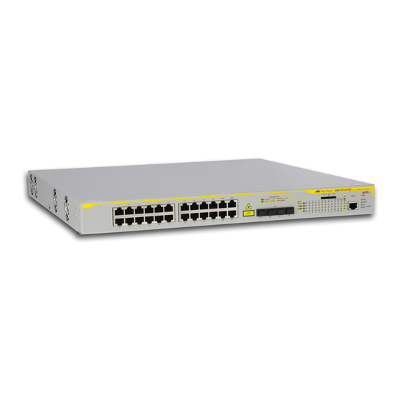
Page 23: X600-24Ts-Poe
One SD slot supporting up to 4GB SD cards Status LEDs for the ports, transceiver slots, and system Redundant power supply connector Two VCS Stacking ports on rear panel Figure 5 shows the x600-24Ts-POE switch front and rear panel. System SD Slot LEDs... -
Page 24: X600-24Ts-Poe
One SD slot supporting up to 4GB SD cards Status LEDs for the ports, transceiver slots, and system Redundant power supply connector Two VCS Stacking ports on rear panel Figure 6 shows the x600-24Ts-POE+ switch front and rear panel. System SD Slot LEDs... -
Page 25: 10/100/1000Base-T Ports
x600 Series Layer 3 Gigabit Ethernet Switches Installation Guide 10/100/1000Base-T Ports This section describes the 10/100/1000Base-T ports on the switches. Connector Type The ports are 8-pin RJ-45 connectors that use four pins at 10 or 100 Mbps and all eight pins at 1000 Mbps. For the pin assignments, refer to “RJ-45 Twisted Pair Port Pinouts”... -
Page 26: Cable Type
Chapter 1: Overview Cable Type The cabling requirements for a 10/100/1000Base-T port are: For 10 Mbps operation: Standard TIA/EIA 568-B-compliant Category 3 or better shielded or unshielded cabling with 100 ohm impedance and a frequency range that extends to 16 MHz. For 100 Mbps operation: Standard TIA/EIA 568-A-compliant Category 5 or TIA/EIA 568-B-compliant Enhanced Category 5 (Cat 5e) shielded or unshielded cabling with 100 ohm impedance and a frequency range... -
Page 27: Sfp Transceiver Slots
Series switch. Figure 7 illustrates an SFP transceiver. Figure 7. SFP Transceiver Refer to “Installing an SFP Transceiver” on page 82 for the SFP installation instructions. Note For a list of supported SFP transceivers, contact your Allied Telesis sales representative. -
Page 28: Xfp Transceiver Slots
Figure 8 shows an example of an XFP transceiver. Figure 8. XFP Transceiver Refer to “Installing an XFP Transceiver” on page 85 for the XFP installation instructions. Note For a list of supported XFP transceivers, contact your Allied Telesis sales representative. -
Page 29: Combo Ports
Ports and Slots x600-24Ts Port 21R with SFP slot 21 x600-24Ts/XP Port 22R with SFP slot 22 x600-24Ts-POE Port 23R with SFP slot 23 x600-24Ts-POE+ Port 24R with SFP slot 24 Follow these guidelines when using these ports and slots: Only one port in a pair, either a 10/100/1000Base-T port or a corresponding SFP module can be active at a time. -
Page 30: Sd Card Slot
Chapter 1: Overview SD Card Slot All of the x600 Series Switches have an SD card slot for storing configuration files and AlliedWare Plus Operating System Software image files on an SD card. See Figure 9. READY BUSY FAULT 1616 Figure 9. -
Page 31: Port Leds
Each port has two LEDs labeled L/A (link/activity) and D/C (duplex mode/ collisions) on the non-PoE models. The x600-24Ts-POE and Base-T LEDs x600-24Ts-POE+ port LEDs are labeled L/A (link/activity) and PoE (Power over Ethernet). Figure 11 shows the port LEDs for the x600-24Ts and x600-24Ts/XP switches. -
Page 32: Figure 13. Port Leds On X600-24Ts-Poe And X600-24Ts-Poe+ Switches
Chapter 1: Overview Figure 13 shows the port LEDs for x600-24Ts-POE and x600-24Ts-POE+ switches. These LEDs are separated from the 10/100/1000Base-T port locations on the front panel. Figure 13. Port LEDs on x600-24Ts-POE and x600-24Ts-POE+ Switches Table 3 describes the LEDs for the Base-T ports. -
Page 33: Sfp Leds
The Duplex Mode and Collisions LED is present on all the x600 switches except for the x600-24Ts-POE and x600-24Ts-POE+ switches. The PoE LED is only present on the x600-24Ts-POE and x600-24Ts-POE+ switches. SFP LEDs There is one LINK/ACTIVITY LED for each SFP slot. The SFP LEDs for the x600 24 port switches are shown in Figure 14. -
Page 34: Xfp Transceiver Slot Leds
Chapter 1: Overview 1618 LINK/ACT LEDs Figure 15. SFP LEDs - x600-48 Port Switch Table 4. SFP Slot LED Descriptions Function State Description No link has been established between the port and the end node. Link Status Solid The port has established a link at 1 and Activity Green Gbps. -
Page 35: Table 5. Xfp Slot Led
x600 Series Layer 3 Gigabit Ethernet Switches Installation Guide Table 5. XFP Slot LED Function State Description Link Status No link has been established between and Activity the port and the end node. Solid The port has established a link at 10 Green Gbps. -
Page 36: System Status Leds
Chapter 1: Overview System STATUS LEDs The system status LEDs on the front panel display general status information. To locate these LEDs, see Figure 17. STATUS FAULT MASTER RESET 1622 Figure 17. System STATUS LEDs See Table 6 for a description of the System STATUS LEDs. Table 6. -
Page 37: Stack Leds
AT-StackXG Stacking Module and if the switch is the master unit of the stack. To locate the STACK LEDs for any of the non-PoE x600 switches, see Figure 18. To locate the STACK LEDs for either the x600-24Ts-POE or x600-24Ts-POE+ switch, see Figure 19. -
Page 38: Table 7. Stack Leds
The expansion slot for the AT-StackXG PRES Stacking Module is empty. Solid The AT-StackXG Stacking Module is installed Green in the switch. The PRES LED is not available on the x600-24Ts-POE and x600-24Ts-POE+ because the stacking ports are permanently installed on the rear panel. -
Page 39: Secure Digital (Sd) Led
x600 Series Layer 3 Gigabit Ethernet Switches Installation Guide Secure Digital (SD) LED All x600 series switches have one Secure Digital (SD) LED shown in Figure 20 and defined in Table 8. READY BUSY FAULT 1616 Figure 20. Secure Digital Slot LED Table 8. -
Page 40: Terminal Port
Chapter 1: Overview Terminal Port The terminal port is used to establish a local (out-of-band) management session with the switch. You establish a local management session by connecting a terminal or a personal computer with a terminal emulation program to the port. The terminal port has an RJ-45 style connector. -
Page 41: Power Over Ethernet (Poe And Poe+)
Series Layer 3 Gigabit Ethernet Switches Installation Guide Power Over Ethernet (PoE and PoE+) The following section applies to x600-24Ts-POE and x600-24Ts-POE+ Gigabit Ethernet switches only. The 10/100/1000Base-T ports on the x600-24Ts-POE switch feature Power over Ethernet (PoE), defined in the IEEE 802.3af standard. -
Page 42: Poe
Chapter 1: Overview Power is injected on the Ethernet cabling along with data by Power Sourcing Equipment (PSE), like an Ethernet LAN switch or router. The IEEE 802.3af, Power over Ethernet specification can provide up to 15.4 watts of power at the PSE. A PD under the IEEE 802.3af specification can use no more than 12.95 watts. -
Page 43: Differences Between Poe, Poe+ And Enhanced Poe
Enhanced PoE delivers between 15.4W and 20W at 48VDC. Enhanced PoE is supported on x600-24Ts-POE, x600-24Ts-POE+ switches. Up to 18 x ports can be configured for Enhanced PoE on x600-24Ts-POE and x600-24Ts-POE+ switches, compared to up to 24 x ports that can be configured for PoE. -
Page 44: Power Classes
SFP combo port. Power Capacity The PSU in the x600-24Ts-POE supplies enough power for the switch itself and for PoE provision for all PoE capable switch ports. However, the PSU in the x600-24Ts-POE+ supplies enough power for the switch itself and enough power is available for PoE+ provision for 12 of the 24 PoE+ capable switch ports. -
Page 45: Implementation
However, the maximum possible PoE+ power requirement (24 ports x 30W ~ 720 watts) is above the maximum amount of power available (370W) for the PSU installed in the x600-24Ts-POE+. This means that you can connect powered devices to 12 ports on the x600-24Ts-POE+ switch... -
Page 46: Redundant Power Supplies
AT-RPS3204 Redundant Power Supply, shown in Figure 21. The RPS connector on the x600-24Ts-POE switch connects to the optional AT-RPS3104 Redundant Power Supply (not shown). Both RPS units can provide power to their respective switches in the event of a failure of the switch’s internal power supply. -
Page 47: At-Lbm (Loop Back) Module
x600 Series Layer 3 Gigabit Ethernet Switches Installation Guide AT-LBM (Loop Back) Module The x600-48Ts/XP switch is shipped from the factory with an AT-LBM module installed in its expansion slot on the rear panel as shown in Figure 22.This module is factory installed for the non-stacking configuration. It provides the capability for a full line rate, nonblocking switching configuration when there are connections on the x600-48Ts/XP switch to all 44 copper ports, two SFP ports, and two XFP ports. -
Page 48: Vcs Stacking Module
Refer to “VC Stacking Module Installation” on page 74 for the AT-StackXG module installation instructions. For further information on stacking, refer to the Allied Telesis Inc. website (www.alliedtelesis.com) for the Overview of Virtual Chassis Stacking (VCS) and the Virtual Chassis Stacking... -
Page 49: Ac Power Connector
x600 Series Layer 3 Gigabit Ethernet Switches Installation Guide AC Power Connector The x600 switches have a single AC power supply socket on the rear panel, which has autoswitch AC inputs. To power the switch on or off, connect or disconnect the power cord. Refer to “Technical Specifications”... - Page 50 Chapter 1: Overview...
-
Page 51: Chapter 2: Virtual Chassis Stacking
Chapter 2: Virtual Chassis Stacking This chapter contains the following sections: “VCStack Introduction” on page 52 “Features of VCStacking” on page 52 “The Physical Stack” on page 52 “Resiliency Link” on page 54 “VCStack Recovery States” on page 54 “Resiliency Link Configurations via Switch Ports” on page 56 “Resilient Stacked Topology”... -
Page 52: Vcstack Tm Introduction
Chapter 2: Virtual Chassis Stacking VCStack Introduction A Virtual Chassis Stack (VCStack) is a group of physically separate switches that are connected so as to function as a single logical switch. In order to function as a VCStack, its component switches are connected using high-speed stacking links. -
Page 53: Figure 24. Back-To-Back Topology (X600 Switches)
x600 Series Layer 3 Gigabit Ethernet Switches Installation Guide Modules, Cables, and Connections VCS Stacking The stacks are connected via the stacking ports on the VCS Stacking Modules (AT-StackXG), which are installed in the back of each switch. The following cables are used to connect the stacking ports of x600 series switches: High Speed Stacking Cables (0.5 meter) - StackXG/0.5 High Speed Stacking Cables (1.0 meter) - StackXG/1... -
Page 54: Resiliency Link
Chapter 2: Virtual Chassis Stacking Ring Configuration A virtual stack using x600 switches can comprise up to 4 stack members connected in a ring topology. Figure 25 shows a ring comprising 3 stacked x600 series switches. Because an alternate path is provided between the stack members, this topology offers a very resilient configuration 100-240VAC~ High Speed Stacking Cables... -
Page 55: Table 10. State Change Table
x600 Series Layer 3 Gigabit Ethernet Switches Installation Guide Table 10. State Change Table Reaction on Reaction on Stack Reaction on Stack Event on Master Node Master Member Member With Resiliency Link Without Resiliency Link Both stack links removed No change Fallback action Re-elect master XEM-STK Removed or Faulty No change... -
Page 56: Resiliency Link Configurations Via Switch Ports
Chapter 2: Virtual Chassis Stacking Resiliency Link Two resiliency-link configurations that connect to switch ports are shown below:Figure 26 shows the resiliency link connecting in a ring topology, Configurations whilst Figure 27 shows the resiliency link connecting to its switch ports via via Switch Ports a network hub. -
Page 57: Resilient Stacked Topology
x600 Series Layer 3 Gigabit Ethernet Switches Installation Guide Resilient Stacked Where network connectivity uptime is a major criteria, you can use virtual chassis stacking to create highly reliable network configurations. Topology Employing link aggregation rather than spanning tree to manage the parallel paths, enables the bandwidth of both data links to be utilized under normal conditions, whilst enabling a single data link to operate should its partner link fail. -
Page 58: Stack Formation
Chapter 2: Virtual Chassis Stacking Stack Formation A virtual chassis stack (VCS) always contains a master plus a number of stack members. To be part of a stack, a switch must connect to other potential stack members via dedicated stacking ports on the VCS Stacking module located in the rear of the switch. - Page 59 x600 Series Layer 3 Gigabit Ethernet Switches Installation Guide Note The ability to independently set both a stack member’s priority and its ID means that the stack master does not need to have an ID of 1; although configuration is simplified by arranging for ID 1 to be the device with the lowest priority value - and thereby forcing it to be the stack master.
-
Page 60: Figure 28. Stack And Status Leds
Chapter 2: Virtual Chassis Stacking management VLAN ID and IP address, use the SHOW STACK command. Stack Member Identification When a switch becomes a member of a VCS Stack it is assigned a Stack Member-ID. Stack status information is displayed on the STACK LEDs shown on the switch’s front panel shown in Figure 28. -
Page 61: Stack Member Failure And Recovery
x600 Series Layer 3 Gigabit Ethernet Switches Installation Guide State Description (Continued) 1- L/A Solid Link on stacking port 1 is active. Green Green Indicates traffic flowing through stacking port 1 Flashing Green OFF Link on stacking port 1 is inactive. 2- L/A Solid Link on stacking port 2 is active. -
Page 62: Vcs Failure Recovery
Chapter 2: Virtual Chassis Stacking VCS Failure If the stack master fails or is removed, the other stack members decide which of two actions to take: Recovery 1. Fallback action. 2. Re-elect a new stack master. Note The master fail-over process will be slower than a stack member failure, and will require the restart (reconvergence) of routing protocols such as RIP. -
Page 63: Stack Maintenance
x600 Series Layer 3 Gigabit Ethernet Switches Installation Guide Stack An operational stack configuration may require occasional maintenance when you need to add, replace or repairing a broken stack stub. Maintenance Adding a Stack Member An unstacked switch can be added to an existing stack (hot swapped in) with minimal impact on traffic. - Page 64 Chapter 2: Virtual Chassis Stacking detected. This situation results in the re-election of one stack master and the re-integration of the stack into one entity. The losing master will return to being a stack member in this process.
-
Page 65: Chapter 3: Installing The Hardware
Chapter 3 Installing the Hardware This chapter provides procedures to install an x600 switch. The chapter contains the following sections: “Reviewing Safety Precautions” on page 66 “Unpacking a Switch” on page 69 “Installing the Power Cord Retaining Clip” on page 70 “Installing the Switches in an Equipment Rack”... -
Page 66: Reviewing Safety Precautions
Note indicates that a translation of the safety statement is available in a PDF document titled “Translated Safety Statements” (613-000990) posted on the Allied Telesis website at www.alliedtelesis.com. Warning: Class 1 Laser product. Warning: Do not stare into the laser beam. - Page 67 x600 Layer 3 Gigabit Ethernet Switch Installation Guide All Countries: Install product in accordance with local and National Electrical Codes. Circuit Overloading: Consideration should be given to the connection of the equipment to the supply circuit and the effect that overloading of circuits might have on overcurrent protection and supply wiring.
- Page 68 Chapter 3: Installing the Hardware Caution: The unit does not contain field serviceable components. Please return damaged units for servicing. Caution: The Ethernet POE ports are only intended for installation in Environment A as defined in IEEE 802.3af. All interconnected equipment must be contained in the same building including the interconnected equipment’s associated LAN connections.
-
Page 69: Unpacking A Switch
2. Place the switch on a level, secure surface. 3. Make sure the following components are included in your switch package. If any item is missing or damaged, contact your Allied Telesis sales representative for assistance. One x600 Series Layer 3 Gigabit Ethernet Switch... -
Page 70: Installing The Power Cord Retaining Clip
Chapter 3: Installing the Hardware Installing the Power Cord Retaining Clip Perform the following procedure to install the power cord retaining clip on the switches: 1. Locate the power cord retaining clip, shown in Figure 29. Figure 29. Power Cord Retaining Clip 2. -
Page 71: Installing The Switches In An Equipment Rack
x600 Layer 3 Gigabit Ethernet Switch Installation Guide Installing the Switches in an Equipment Rack Perform the following procedure to install each switch in a standard 19-inch rack: Note Steps 1, 2, and 3 are optional. These steps provide instructions on how to remove the snap-on plastic feet from the bottom of a switch. -
Page 72: Figure 33. Mounting The Switch In A Rack
Chapter 3: Installing the Hardware 5. Install the second rack-mount bracket on the other side of the switch with the four remaining screws. 6. Mount the switch in a 19-inch rack using standard screws (not provided), as shown in Figure 33. 0 0 L IN A C T C O L... -
Page 73: Resetting The Switch
x600 Layer 3 Gigabit Ethernet Switch Installation Guide Resetting the Switch You may need to reset the switch after upgrading the firmware or after you have made a configuration change that requires resetting the switch to activate the change. To reset the x600 switch, perform the following procedure: 1. -
Page 74: Vc Stacking Module Installation
Chapter 3: Installing the Hardware VC Stacking Module Installation Overview When you are preparing the x600 switches for a VC Stack configuration, the VC Stacking Module (AT-StackXG) must be installed in the expansion slot on the rear panel of the unit. The AT-StackXG module is shown in Figure 35. -
Page 75: Installing The At-Stackxg Module
x600 Layer 3 Gigabit Ethernet Switch Installation Guide Installing the To install the AT-StackXG module, perform the following procedure: AT-StackXG 1. Remove the module from the shipping package. Module Note Store the packaging material in a safe location. You must use the original shipping material if you need to return the unit to Allied Telesis. -
Page 76: Figure 37. Installing The At-Stackxg Stacking Module
Chapter 3: Installing the Hardware Caution Do not force AT-StackXG module into place. Doing so may damage the connector pins on the backplane inside the chassis. If there is resistance, remove the module and reinsert it after verifying that the edges of the card are properly aligned in the guides in the chassis’... -
Page 77: Figure 39. Removing The Plastic Protector
x600 Layer 3 Gigabit Ethernet Switch Installation Guide Note Do not cable AT-StackXG module until you have prepared the switch’s Alliedware Plus Operating System software on the x600 Series Switches as explained in the x600 series AlliedWare Plus 5.3.1 Software Reference. 5. - Page 78 Chapter 3: Installing the Hardware...
-
Page 79: Chapter 4: Cabling The Network Ports
Chapter 4 Cabling the Network Ports This chapter contains the instructions for attaching network cables to an x600 switch. The chapter contains the following sections: “Twisted Pair and Fiber Optic Specifications” on page 80 “Installing SFP/XFP Transceivers” on page 82 “Cabling the 10/100/1000Base-T and Fiber Optic Ports”... -
Page 80: Twisted Pair And Fiber Optic Specifications
Chapter 4: Cabling the Network Ports Twisted Pair and Fiber Optic Specifications Twisted Pair Table 12 lists the cabling specifications for the 10/100/1000Base-T twisted pair ports. Cable Specifications Table 12. Twisted Pair Cabling and Distances Maximum Speed Cable Type Operating Distance 10 Mbps Standard TIA/EIA 568-B-compliant... -
Page 81: Sfp/Xfp Transceiver Specifications
Layer 3 Gigabit Ethernet Switch Installation Guide SFP/XFP The specifications for an optional SFP or XFP transceiver can be found on our Allied Telesis web site at www.alliedtelesis.com. Transceiver Specifications... -
Page 82: Installing Sfp/Xfp Transceivers
Chapter 4: Cabling the Network Ports Installing SFP/XFP Transceivers Review the following guidelines before installing an optional SFP or XFP transceiver in a switch: A transceiver can be hot-swapped; the switch can be powered on when you install it. However, you should always disconnect the cables first before removing a transceiver. -
Page 83: Figure 41. Installing An Sfp Transceiver
x600 Layer 3 Gigabit Ethernet Switch Installation Guide 2. Remove the transceiver from its shipping container and store the packaging material in a safe location. 3. Position the transceiver with the label facing up. 4. Slide the transceiver into the slot until it clicks into place. See Figure 2 3 R C L A S L A S E... -
Page 84: Figure 43. Positioning Sfp Handles On The X600-48Ts And X600-48Ts/Xp Switches
Chapter 4: Cabling the Network Ports 6. For the x600-48Ts and x600-48Ts/XP switches, verify that handles on the top two SFP modules are in the up position and the bottom two SFP modules are in the down position as show in Figure 43. S F P x 6 0 0 L a y e... -
Page 85: Installing An Xfp Transceiver
x600 Layer 3 Gigabit Ethernet Switch Installation Guide Installing an XFP To install an XFP transceiver in an x600 switch, perform the following procedure: Transceiver 1. Remove the dust plug from a transceiver slot on the switch. Refer to Figure 44. L/ A P O R T 1 0 0 0... - Page 86 Chapter 4: Cabling the Network Ports 5. Repeat this procedure to install a second XFP transceiver or go to “Cabling the 10/100/1000Base-T and Fiber Optic Ports” on page 87. For XFP optical and cabling specifications, consult the documentation shipped with the module.
-
Page 87: Cabling The 10/100/1000Base-T And Fiber Optic Ports
x600 Layer 3 Gigabit Ethernet Switch Installation Guide Cabling the 10/100/1000Base-T and Fiber Optic Ports Observe the following guidelines when connecting a twisted pair or fiber optic cable to a port on the switch: The connector on the cable should fit snugly into the port on the switch. -
Page 88: Powering On A Switch
Chapter 4: Cabling the Network Ports Powering on a Switch To power on a switch, perform the following procedure: 1. Position the power cord retaining clip in the up position, as shown in Figure 46. 1 0 0 - 2 4 0 V A Figure 46. -
Page 89: Starting A Local Management Session
x600 Layer 3 Gigabit Ethernet Switch Installation Guide 3. Connect the other end of the power cord to an appropriate AC power outlet. For power specifications for the switch, refer to “Power Specifications” on page 104. 4. Start a local management session on the unit by performing the next procedure. - Page 90 Chapter 4: Cabling the Network Ports 3. Configure the terminal or terminal emulation program as follows: Baud rate: Default is 9600 bps (Range is 9600 to 115200 bps) Data bits: 8 Parity: None Stop bits: 1 Flow control: None Note The port settings are for a DEC VT100 or ANSI terminal, or an equivalent terminal emulator program.
-
Page 91: Warranty Registration
Layer 3 Gigabit Ethernet Switch Installation Guide Warranty Registration For warranty information and registration, go to the Allied Telesis web site at www.alliedtelesis.com/warranty. - Page 92 Chapter 4: Cabling the Network Ports...
-
Page 93: Chapter 5: Troubleshooting
“Issues with Virtual Stacking Chassis Configuration” on page 102 Note If you are unable to resolve the problem after following the instructions in this chapter, contact Allied Telesis Technical Support for assistance. Refer to “Contacting Allied Telesis” on page 16 for contact information. -
Page 94: Power Led Is Off
Chapter 5: Troubleshooting Power LED is Off Check the PWR LED on the front of the switch. If the LED is off, indicating that the unit is not receiving power, do the following: Make sure the power cord is securely connected to the power source and to the AC connector on the rear panel of the switch. -
Page 95: Twisted Pair Port Link Led Is Off
x600 Layer 3 Gigabit Ethernet Switch Installation Guide Twisted Pair Port Link LED is Off When a twisted pair port on the switch is connected to a properly operating end node, the Link LED for the port should be on. If a Link LED is off, do the following: Note A 1000Base-T connection can take from five to ten seconds to... -
Page 96: Sfp Or Xfp Led Is Off
Chapter 5: Troubleshooting SFP or XFP LED is Off When a fiber optic port on the switch is connected to a properly operating end node, the Link LED for the port should be on. If a Link LED is off, do the following: Verify that the end node connected to the port is powered ON and is operating properly. -
Page 97: Transceiver Is Installed But The Status Is "Not Present
x600 Layer 3 Gigabit Ethernet Switch Installation Guide Transceiver is Installed but the Status is “Not Present” If a SFP or XFP transceiver is installed in a transceiver slot but the Uplink Information menu in the AlliedWare Plus Operating System Software interface displays “Not Present”... -
Page 98: System Fault Led Is Blinking
Chapter 5: Troubleshooting System Fault LED is Blinking A blinking FAULT LED indicates that the switch is updating the active boot configuration file or a new version of the operating system software is in the process of being downloaded to the switch. The LED stops blinking after the switch has completed updating the boot configuration file or downloading the operating system software. -
Page 99: System Fault Led Is Steadily On
If the FAULT LED remains ON, download a new version of the switch’s operating system software. For instructions, refer to the AlliedWare Plus Operating System Software Reference Guide. Note If the FAULT LED remains steadily on, contact Allied Telesis Technical Support for assistance. See “Contacting Allied Telesis” on page 16. -
Page 100: Cannot Establish A Local (Out-Of-Band) Management Session
Chapter 5: Troubleshooting Cannot Establish a Local (Out-of-Band) Management Session If you are unable to establish a local (out-of-band) management session with the switch through the terminal port on the front panel, do the following: Check that the RJ-45 serial management cable is securely connected to the serial terminal port on the switch and to the RS-232 port on the terminal or personal computer. -
Page 101: Switch Functions Intermittently
x600 Layer 3 Gigabit Ethernet Switch Installation Guide Switch Functions Intermittently If a switch functions intermittently, check the system hardware status through the management interface: Note the current voltage for the power supply compared to the optimum rating. Verify that the system temperature is within the operating range. -
Page 102: Issues With Virtual Stacking Chassis Configuration
Chapter 5: Troubleshooting Issues with Virtual Stacking Chassis Configuration For information on issues with stacking, refer to the Allied Telesis Inc. website (www.alliedtelesis.com) for the Overview of Virtual Chassis Stacking (VCS) and the Virtual Chassis Stacking section of the AW+... -
Page 103: Appendix A: Technical Specifications
(1.72 in. x 17.34 in. x 12.0 in.) x600-48Ts/XP 44 mm x 440 mm x 305 mm (1.72 in. x 17.34 in. x 12.0 in.) x600-24Ts-POE 44 mm x 440 mm x 408 mm (1.72 in. x 17.34 in. x 16.06 in.) x600-24Ts-POE+ 44 mm x 440 mm x 408 mm (1.72 in. -
Page 104: Environmental Specifications
100-240V AC, 2.0 A maximum, 50/60 Hz AC Input (POE Model) 100-240V AC, 6.0 A maximum, 50/60 Hz PoE and PoE+ Output Voltage: DC Output x600-24Ts-POE 48V DC, 10-350 mA, 15.4 watts/port (IEEE 802.3af) 48V DC, 10-470 mA, 20 watts/port... -
Page 105: Certifications
Electrical and Laser Safety: EN60950-1 (TUV), EN60825-1 (TUV), UL 60950-1 ( ), CSA-C22-2 No. 60950-1 ( Quality and Reliability (MTBF): x600-24Ts 130,000 hrs. x600-24Ts/XP 130,000 hrs. x600-48Ts 90,000 hrs. x600-48Ts/XP 90,000 hrs. x600-24Ts-POE 90,000 hrs. x600-24Ts-POE+ 90,000 hrs. Compliance Marks: , TUV, C-Tick... -
Page 106: Rj-45 Twisted Pair Port Pinouts
Appendix A: Technical Specifications RJ-45 Twisted Pair Port Pinouts Figure 49 illustrates the pin layout of an RJ-45 connector and port. Pin 1 Figure 49. RJ-45 Connector and Port Pin Layout Table 13 lists the pin signal definitions when a port is operating in the MDI configuration at 10 or 100 Mbps. -
Page 107: Table 15. Pin Signals - 1000 Mbps
x600 Layer 3 Gigabit Ethernet Switch Installation Guide Table 15 lists the pin signal definitions when a port operating at 1000 Mbps. Table 15. Pin Signals - 1000 Mbps Pinout Pair Pair 1 + Pair 1 - Pair 2 + Pair 3 + Pair 3 - Pair 2 -... -
Page 108: Rj-45 Style Serial Terminal Port Pinouts
Request to Send AT-RPS3104 17-pin Connector Pinouts Figure 50 illustrates the pin layout of the RPS 17-pin D-combo port and connector used to connect the AT-RPS3104 Redundant Power Supply to the x600-24Ts-POE and x600-24Ts-POE+ switches. Figure 50. AT-RPS3104 17-Pin Connector Layout... -
Page 109: Table 17. At-Rps3104 17-Pin Connector Pinout Definitions
x600 Layer 3 Gigabit Ethernet Switch Installation Guide Table 17 lists the RPS 17-pin D-combo port and connector pinout definitions. Table 17. AT-RPS3104 17-Pin Connector Pinout Definitions Definition 48V Return Return 48V RS+ Redundant Power Supply (RPS) present RPS_EN 12V RS+ 3.3V 48V RS- RPS GOOD... -
Page 110: At-Rps3204 21-Pin D-Combo Port And Connector Pinouts
Appendix A: Technical Specifications AT-RPS3204 21-pin D-combo Port and Connector Pinouts Figure 51 illustrates the pin layout of the RPS 21-pin D-combo port and connector used to connect the AT-RPS3204 Redundant Power Supply to a non-POE x600 Series Switch. Figure 51. AT-RPS3204 21-pin D-combo Connector and Port Pin Layout Table 18 lists the RPS 21-pin D-combo port and connector pinout definitions. - Page 111 x600 Layer 3 Gigabit Ethernet Switch Installation Guide Table 18. AT-RPS3204 21-pin Connector Pinout Definitions Definition Ground Ground Ground +12.0 VDC sense Ground No connect +12.0 VDC...
- Page 112 Appendix A: Technical Specifications...
Need help?
Do you have a question about the x600-24Ts-POE and is the answer not in the manual?
Questions and answers