Sign In
Upload
Manuals
Brands
Allied Telesis Manuals
Switch
x330-52GTX
Allied Telesis x330-52GTX Manuals
Manuals and User Guides for Allied Telesis x330-52GTX. We have
1
Allied Telesis x330-52GTX manual available for free PDF download: Installation Manual
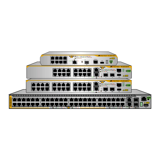
Allied Telesis x330-52GTX Installation Manual (172 pages)
Fanless Gigabit Layer 3 Access Switches for Virtual Chassis Stacking
Brand:
Allied Telesis
| Category:
Switch
| Size: 6.8 MB
Table of Contents
Table of Contents
7
Preface
15
Document Conventions
16
Contacting Allied Telesis
17
Chapter 1: Overview
20
Front and Back Panels
20
Figure 1: Front Panel of the X330-10GTX Switch
20
Figure 2: Front Panel of the X330-20GTX Switch
20
Figure 3: Front Panel of the X330-28GTX Switch
21
Figure 4: Front Panel of the X330-52GTX Switch
21
Figure 5: Back Panels
22
Features
23
10/100/1000Mbps Copper Ports
23
1/2.5/5/10Gbps Multi-Gigabit Copper Ports
23
1/10Gbps SFP+ Ports
23
Port and System Leds
24
Installation Options
24
MAC Address Table
24
Management Software and Interfaces
25
Energy Savings
25
10/100/1000Mbps Copper Ports
26
1/2.5/5/10Gbps Multi-Gigabit Copper Ports
28
SFP+ Ports
30
Port Leds
31
10/100/1000Mbps Copper Port Leds
31
Figure 6: Speed/Activity and Duplex Mode Leds for the 10/100/1000Mbps Copper Ports
31
1/2.5/5/10Gbps Multi-Gigabit Copper Port Leds
33
Figure 7: Speed/Activity Leds for the 1/2.5/5/10Gbps Multi-Gigabit Copper Ports
33
1/10Gbps SFP+ Port Leds
34
Figure 8: Speed/Activity Leds for the 1/10Gbps SFP+ Ports
34
Eco-Friendly Button
36
Switch ID LED
37
Figure 9: Switch ID LED
37
Figure 10: Switch ID LED with Eco-Friendly Mode off (Port Leds On)
37
Figure 11: Switch ID LED with Eco-Friendly Mode on (Port Leds Off)
38
USB Port
39
Console Port
40
Power Supply and Power Savings Features
41
Chapter 2: Virtual Chassis Stacking
43
Overview
44
Stacking Guidelines
45
Stack Trunks
46
SFP+ Ports S1 and S2
46
Figure 12: Stack Trunks of SFP+ Ports S1 and S2 for Two Switches
47
Figure 13: Stack Trunks of SFP+ Ports S1 and S2 for Three Switches
47
Figure 14: Stack Trunks of SFP+ Ports S1 and S2 for Four Switches
48
Figure 15: Mixed Stack of X330 Switches
48
Multi-Gigabit Copper Ports
49
Figure 16: Chain Stack Trunk of SFP+ Ports S1 and S2
49
Figure 17: Stack Trunks of Multi-Gigabit Copper Ports for Two Switches
49
Figure 18: Stack Trunks of Multi-Gigabit Copper Ports for Three Switches
50
Figure 19: Stack Trunks of Multi-Gigabit Copper Ports for Four Switches
50
Unsupported Trunks
51
Figure 20: Chain Stack Trunk of Multi-Gigabit Copper Ports
51
Figure 21: Unsupported Trunk of Multi-Gigabit Copper Ports and SFP+ Ports S1 and S2
51
Figure 22: Unsupported Trunk of SFP+ Ports S1 and S2 with Mixed Cables
52
Figure 23: Unsupported Trunk with a Network Device between Trunk Ports
53
Master and Member Switches
54
Switch ID Numbers
55
Feature Licenses
56
Planning the Stack
57
Specifying Ports in the Command Line Interface
58
Figure 24: PORT Parameter in the Command Line Interface
58
Vcstack Worksheet
60
Chapter 3: Beginning the Installation
65
Reviewing Safety Precautions
66
Choosing a Site for the Switch
70
Site Requirements
70
Enclosure Requirements
71
Unpacking the Switch
72
Figure 25: Accessory Items Included with the X330-20GTX Switch
72
Figure 26: Accessory Items Included with the X330-28GTX Switch
73
Figure 27: Accessory Items Included with the X330-52GTX Switch
74
Installation Options
75
X330-20GTX Switch
75
Figure 28: Installation Options for the X330-20GTX Switch
75
X330-28GTX Switch
76
Figure 29: Installation Options for the X330-28GTX Switch
76
X330-52GTX Switch
77
Figure 30: Installation Options for the X330-52GTX Switch
77
Hardware Options
78
RKMT-J13 Equipment Rack Brackets Kit
78
Figure 31: RKMT-J13 Equipment Rack Brackets Kit for the X330-20GTX Switch
78
BRKT-J24 Wall Brackets Kit
79
Figure 32: BRKT-J24 Wall Brackets Kit for the X330-20GTX and X330-28GTX Switches
79
Recording the Serial Number and MAC Address
80
Figure 33: Serial Number and MAC Address Labels
80
Installing the Switch on a Table
81
Figure 34: Switch Installation on a Table
81
Figure 35: Unsupported Table Installations
81
Figure 36: Attaching the Bumper Feet
82
Figure 37: Attaching Bumper Feet on the X330-52GTX Switch
83
Chapter 4: Installing the X330-20GTX Switch in an Equipment Rack
85
Introduction
86
Figure 38: X330-20GTX Switch with RKMT-J13 Equipment Rack Brackets Kit
86
Installing the X330-20GTX Switch
87
Figure 39: Attaching the Handles to the RKMT-J13 Brackets
87
Figure 40: Attaching the Extenders to the RKMT-J13 Brackets
88
Figure 41: Attaching the RKMT-J13 Brackets to the X330-20GTX Switch
88
Figure 42: Securing the X330-20GTX Switch in a Standard 19-Inch Equipment Rack
89
Chapter 5: Installing the X330-28GTX Switch in an Equipment Rack
91
Introduction
92
Figure 43: X330-28GTX Switch Installed in a Standard 19-Inch Equipment Rack
92
Installing the X330-28GTX Switch
93
Figure 44: Attaching the Equipment Rack Brackets to the X330-28GTX Switch
93
Figure 45: Securing the X330-28GTX Switch in a Standard 19-Inch Equipment Rack
94
Chapter 6: Installing the X330-52GTX Switch in an Equipment Rack
95
Introduction
96
Figure 46: Bracket Screw Holes on the X330-52GTX Switch
96
Figure 47: Equipment Rack Bracket Positions for the X330-52GTX Switch
96
Installing the X330-52GTX Switch
97
Figure 48: Attaching the Equipment Rack Brackets to the X330-52GTX Switch
97
Figure 49: Securing the X330-52GTX Switch in a Standard 19-Inch Equipment Rack
98
Chapter 7: Installing X330-20GTX, X330-28GTX, and X330-52GTX Switches on a Wall
100
Installation Guidelines
100
Figure 50: X330-20GTX and X330-28GTX Switches on a Wall
100
Figure 51: X330-52GTX Switch on a Wall
100
Figure 52: Unsupported Wall Installation for the X330-20GTX, X330-28GTX, and X330-52GTX Switches
101
Plywood Base for a Wall with Wooden Studs
103
Figure 53: X330 Switch on a Wall with a Plywood Base
103
Figure 54: Steps to Installing X330 Switches on a Plywood Base
104
Installing the Switch
105
Figure 55: Attaching the AT-BRKT-J24 Wall Brackets to X330-20GTX and X330-28GTX Switches
106
Figure 56: Attaching the Wall/Equipment Rack Brackets to the X330-52GTX Switch
106
Figure 57: Attaching the Wall/Equipment Rack Brackets to the X330-52GTX Switch (Continued)
107
Figure 58: Marking the Locations of the Bracket Holes
108
Chapter 8: Displaying the Hardware Status and Alliedware Plus Version Number
109
Powering on the Switch
110
Figure 59: Installing the Power Cord Retaining Clip
110
Figure 60: Connecting the AC Power Cord
110
Figure 61: Lowering the Power Cord Retaining Clip
111
Figure 62: Connecting the Power Cord to an AC Power Outlet
111
Starting a Local Management Session
112
Figure 63: Management Cable Included with Switch
112
Figure 64: VT-Kit3 Management Cable
112
Figure 65: Local Management Sessions with the VT-Kit3 Management Cable
113
Displaying the Hardware Status and Alliedware Plus Version Number
115
Figure 66: Disconnecting the Power Cord from the AC Power Source
115
Chapter 9: Building Stacks with SFP+ Ports S1 and S2
117
Introduction
118
Powering on the Switches Sequentially
119
Powering on the Switches Simultaneously
121
Verifying the Stack and Assigning Priority Numbers
123
Figure 67: SHOW STACK Command
123
Figure 68: Moving to the Global Configuration Mode with the ENABLE and CONFIGURE TERMINAL Commands
124
Figure 69: Returning to the Privileged Exec Mode
125
Figure 70: Saving the Priority Values with the WRITE Command
125
Figure 71: SHOW STACK Command with New Switch Priority Values
125
Chapter 10: Building Stacks with Multi-Gigabit Copper Ports
127
Introduction
128
Command Summary
129
STACK ENABLE Command
129
STACKPORT Command
129
STACK PRIORITY Command
130
STACK RENUMBER Command
131
SWITCH PROVISION Command
132
Configuring the Master Switch
133
General Steps for the Master Switch
133
Configuring the Master Switch - Part I
134
Configuring the Master Switch - Part II
136
Verifying the Master Switch
138
Figure 72: SHOW STACK Command on the Master Switch
138
Figure 73: SHOW RUNNING-CONFIG INTERFACE Command on the Master Switch
139
What to Do Next
140
Figure 74: Powering off the Switch
140
Configuring Member Switches
141
General Steps for Member Switches
141
Configuring Member Switches - Part I
142
Configuring Member Switches - Part II
143
Verifying Member Switches
145
Figure 75: SHOW STACK Command for a Member Switch
145
Figure 76: SHOW RUNNING-CONFIG INTERFACE Command for Member Switches
146
What to Do Next for Member Switches
147
Powering on the Stack
148
Chapter 11: Cabling Copper and SFP+ Ports
149
Cabling Copper Ports
150
Guidelines to Handling SFP and SFP+ Transceivers
151
Installing 1Gbps SFP and 10Gbps SFP+ Transceivers
152
Figure 77: Installing an SFP+ Transceiver
152
Figure 78: Removing the Dust Cover from an SFP+ Transceiver
153
Figure 79: Positioning the SFP+ Handle in the Upright Position
153
Figure 80: Connecting a Fiber Optic Cable to an SFP or SFP+ Transceiver
154
Installing AT-SP10TW Direct Connect Twinax Cables in SFP+ Ports
155
Figure 81: Installing an AT-SP10TW Cable
155
Chapter 12: Troubleshooting
157
Appendix A: Technical Specifications
161
Physical Specifications
162
Figure 82: Dimensions of the X330-10GTX Switch
162
Figure 83: Dimensions of X330-20GTX and X330-28GTX Switches
163
Figure 84: Dimensions of the X330-52GTX Switch
163
Figure 85: Bracket Screw Holes on the X330-20GTX and X330-28GTX Switches
164
Figure 86: Bracket Screw Holes on the X330-52GTX Switch
165
Environmental Specifications
166
Power Specifications
167
Certifications
169
Copper Port Pinouts
171
Figure 87: Pin Layout for the RJ-45 Copper Ports (Front View)
171
Style Serial Console Port Pinouts
172
Advertisement
Advertisement
Related Products
Allied Telesis x330-10GTX
Allied Telesis x330 Series
Allied Telesis x330-20GTX
Allied Telesis x330-28GTX
Allied Telesis x3100 Series
Allied Telesis SwitchBlade x3106
Allied Telesis x310-26FP
Allied Telesis x310-50FP
Allied Telesis x320 Series
Allied Telesis x320-10GH
Allied Telesis Categories
Switch
Network Router
Media Converter
Network Hardware
Wireless Access Point
More Allied Telesis Manuals
Login
Sign In
OR
Sign in with Facebook
Sign in with Google
Upload manual
Upload from disk
Upload from URL