Sign In
Upload
Manuals
Brands
Allied Telesis Manuals
Switch
SwitchBlade x3112
Allied Telesis SwitchBlade x3112 Manuals
Manuals and User Guides for Allied Telesis SwitchBlade x3112. We have
1
Allied Telesis SwitchBlade x3112 manual available for free PDF download: Installation Manual
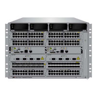
Allied Telesis SwitchBlade x3112 Installation Manual (223 pages)
Access Edge Chassis Switch
Brand:
Allied Telesis
| Category:
Switch
| Size: 5.72 MB
Table of Contents
Table of Contents
5
Preface
15
Safety Symbols Used in this Document
16
Contacting Allied Telesis
17
Chapter 1: Overview
19
Introduction
20
Figure 1: AT-Sbx3112 Chassis
20
Figure 2: Ethernet Line Cards and AT-Sbx31Cfc Central Fabric Controller Card
20
Figure 3: Ethernet Line Cards and AT-Sbx31Cfc Central Fabric Controller Card (Continued)
21
Figure 4: Power Supply Units
21
Figure 5: Fan Module
22
AT-Sbx3112 Chassis
23
Figure 6: Front View of the AT-Sbx3112 Chassis
23
Figure 7: Rear View of the AT-Sbx3112 Chassis
24
Figure 8: AT-Sbx3112 Chassis with Line Cards, Control Cards, and Power Supplies
24
Ethernet Line and Control Cards Slots
25
Figure 10: Power Supply Slots
25
Figure 9: Slots for the Ethernet Line and Control Cards
25
Power Supply Slots
25
AT-Sbx31Gt24 Line Card
27
Figure 11: AT-Sbx31Gt24 Line Card
27
AT-Sbx31Gt40 Line Card
28
Figure 12: AT-Sbx31Gt40 Line Card
28
AT-Sbx31Gp24 Poe Line Card
29
Figure 13: AT-Sbx31Gp24 Poe Line Card
29
AT-Sbx31Gs24 SFP Line Card
30
Figure 14: AT-Sbx31Gs24 SFP Line Card
30
AT-Sbx31Gc40 Line Card
31
Figure 15: AT-Sbx31Gc40 Line Card
31
AT-Sbx31Xz4 XFP Line Card
33
Figure 16: AT-Sbx31Xz4 XFP Line Card
33
AT-Sbx31Xs6 SFP+ Line Card
34
Figure 17: AT-Sbx31Xs6 Line Card
34
10/100/1000Base-T Twisted Pair Ports
35
Connector Type
35
Speed
35
Duplex Mode
35
Maximum Distance
36
Cable Requirements
36
Table 1. Twisted Pair Cable for the AT-Sbx31Gt24 and AT-Sbx31Gt40 Line Cards
36
Automatic MDIX Detection
37
Straight-Through or Crossover Cabling
37
Table 2. Twisted Pair Cable for the AT-Sbx31Gp24 Line Card
37
Port Pinouts
38
Power over Ethernet on the AT-Sbx31Gp24 Line Card
39
Powered Device Classes
39
Table 3. Ieee802.3Af and Ieee802.3At Powered Device Classes
39
Power Budgeting
40
Poe Wiring
40
Table 4. Maximum Number of Powered Devices
40
Port Numbers on the AT-Sbx31Gc40 Line Card
42
Figure 18: Port Numbers for Slots with CSFP Transceivers
42
Figure 19: Port Numbers for Slots with Standard SFP Transceivers
43
Port Leds on the Ethernet Line Cards
44
AT-Sbx31Gt24 Line Card
44
Figure 20: Port Leds on the AT-Sbx31Gt24 Line Card
44
Table 5. Port Leds on the AT-Sbx31Gt24 Line Card
44
AT-Sbx31Gt40 Line Card
45
Figure 21: Port Leds on an RJ Point 5 Cable Connector for the AT-Sbx31Gt40 Line Card
45
Figure 22: Link/Activity LED on an RJ Point 5 Cable Connector for the AT-Sbx31Gt40 Line Card
45
AT-Sbx31Gp24 Line Card
46
Figure 23: Port Leds on the AT-Sbx31Gp24 Poe Line Card
46
Table 6. Port Leds for the AT-Sbx31Gt40 Line Card
46
Table 7. Port Leds on the AT-Sbx31Gp24 Poe Line Card
47
AT-Sbx31Gs24 Line Card
48
Figure 24: Port Leds on the AT-Sbx31Gs24 SFP Line Card
48
Table 8. Port Leds on the AT-Sbx31Gs24 SFP Line Card
48
AT-Sbx31Gc40 Line Card
49
Figure 25: Leds for the AT-Sbx31Gc40 Line Card
49
Figure 26: Leds for the AT-Sbx31Gc40 Line Card, with CSFP Transceivers
49
Figure 27: Leds for the AT-Sbx31Gc40 Line Card, with SFP Transceivers
50
Table 9. Transceiver Slot Leds on the AT-Sbx31Gc40 Line Card
50
AT-Sbx31Xz4 Line Card
51
AT-Sbx31Xs6 Line Card
51
Figure 28: Transceiver Slot Leds on the AT-Sbx31Xz4 XFP Line Card
51
Figure 29: SFP+ Slot Leds on the AT-Sbx31Xs6 Line Card
51
Table 10. Transceiver Slot Leds on the AT-Sbx31Xz4 XFP Line Card
51
Table 11. SFP+ Slot Leds on the AT-Sbx31Xs6 Line Card
52
AT-Sbx31Cfc Central Fabric Controller Card
53
SYS Status Leds
54
Figure 30: AT-Sbx31Cfc Central Fabric Controller Card
54
Table 12. SYS (System) Status Leds
54
Sbx STATUS Leds
55
Table 13. Sbx STATUS Leds
55
Eco-Friendly Button
56
Reset Button
56
NET MGMT Port
58
Table 14. Features that Use the NET MGMT Port
58
Net Mgmt Led
60
Console (RS-232) Port
60
SD Card Slot
60
Table 15. NET MGMT Port LED
60
SD Status LED
61
USB Port
61
Table 16. SD Status LED
61
Power Supplies
62
Leds
63
Table 17. Leds on the AT-Sbxpwrsys1 AC Power Supply
63
Table 18. Leds on the AT-Sbxpwrsys1 DC Power Supply
64
Table 19. Leds on the AT-Sbxpwrpoe1 AC Power Supply
64
AT-Sbxfan12 Module
65
Led
65
Figure 31: AT-Sbxfan12 Module
65
Table 20. AT-Sbxfan12 Module LED
65
Power Supply Interfaces (Opto-Couplers)
66
Led
66
Figure 32: Power Supply Interfaces (Opto-Couplers)
66
Table 21. Power Supply Interface LED
66
Module Names in the Management Software
67
Table 22. Card Types in the Management Software
67
Management Software Releases for the Hardware Components
68
Table 23. Management Software Releases for the Hardware Components
68
Chapter 2: Safety Precautions and Site Preparation
69
Reviewing Safety Precautions
70
Selecting a Site for the Switchblade X3112
74
Figure 33: 100 - 125 VAC 125 V NEMA 5-20 Plug and Receptacle
75
Chapter 3: Installing the Chassis in an Equipment Rack
77
Required Tools and Material
78
Preparing the Equipment Rack
79
Figure 34: Reserving Vertical Rack Space
80
Figure 35: Rack Mounting Hole Locations
81
Unpacking the AT-Sbx3112 Chassis
82
Figure 36: AT-Sbx3112 Chassis Items
82
Figure 37: AT-Sbx3112 Chassis Items (Continued)
83
Adjusting the Equipment Rack Brackets
84
Table 24. Front Panel to Rack Rail Dimensions
84
Figure 38: Rack Mounting Bracket Locations
85
Figure 39: Rack Bracket Locations for Reverse Position of Chassis
85
Installing the AT-Sbx3112 Chassis in the Equipment Rack
86
Figure 40: Lifting the AT-Sbx3112 Chassis into the Equipment Rack
87
Figure 41: Installing the Rack Mount Screws
88
Removing the Shipping Brace
89
Figure 42: Removing the Shipping Brace
89
Installing the Chassis Grounding Lug
90
Figure 43: Stripping the Grounding Wire
90
Figure 44: Removing the Grounding Lug
90
Figure 45: Attaching the Grounding Wire to the Grounding Lug
91
Figure 46: Installing the Grounding Lug and Wire
91
Chapter 4: Installing the Power Supplies
93
Protecting against Electrostatic Discharge (ESD)
94
Figure 47: ESD Socket and Wrist Strap
94
Installing the AT-Sbxpwrsys1 AC System Power Supply
95
Figure 48: Power Supply Slots
95
Figure 49: Removing the Blank Slot Cover from Power Supply Slot C
96
Figure 50: Items Included with the AT-Sbxpwrsys1 Power Supply Module
97
Figure 51: Verifying the AT-Sbxpwrsys1 AC Power Supply
98
Figure 52: Raising the Handle on the AT-Sbxpwrsys1 AC Power Supply
98
Figure 53: Inserting the AT-Sbxpwrsys1 AC Power Supply
99
Figure 54: Lowering the Handle on the AT-Sbxpwrsys1 AC Power Supply
100
Installing the AT-Sbxpwrpoe1 AC Power Supply
101
Figure 55: Power Supply Slots
101
Figure 56: Removing the Blank Slot Cover from Power Supply Slot a
102
Figure 57: Items Included with the AT-Sbxpwrpoe1 Power Supply Module
103
Figure 58: Verifying the AT-Sbxpwrpoe1 AC Power Supply
104
Figure 59: Raising the Handle on the AT-Sbxpwrpoe1 AC Power Supply
104
Figure 60: Inserting the AT-Sbxpwrpoe1 AC Power Supply
105
Figure 61: Locking the Handle on the AT-Sbxpwrpoe1 AC Power Supply
106
Installing the AT-Sbxpwrsys1 DC Power Supply
107
Figure 62: Power Supply Slots
107
Figure 63: Removing the Blank Slot Cover from Power Supply Slot C
108
Figure 64: Items Included with the AT-Sbxpwrsys1 DC Power Supply Module
109
Figure 65: Loosening the Handle Locking Screw on the AT-Sbxpwrpoe1 DC Power Supply
110
Figure 66: Raising the Handle on the AT-Sbxpwrpoe1 DC Power Supply
110
Figure 67: Inserting the AT-Sbxpwrsys1 DC Power Supply
111
Figure 68: Locking the Handle on the AT-Sbxpwrsys1 Power Supply
112
Chapter 5: Installing the AT-Sbx31Cfc Card and Ethernet Line Cards
113
Installing the AT-Sbx31Cfc Central Fabric Controller Card
114
Figure 69: Slots 4 and 5 for the AT-Sbx31Cfc Card
114
Figure 70: Items Included with the AT-Sbx31Cfc Central Fabric Controller Card
115
Figure 71: Opening the Locking Handles on the AT-Sbx31Cfc Central Fabric Controller Card
115
Figure 72: Removing the Battery Insulator
116
Figure 73: Aligning the AT-Sbx31Cfc Card in the Chassis Slot
116
Figure 74: Inserting the AT-Sbx31Cfc Card in the Chassis Slot
117
Figure 75: Closing the Locking Levers on the AT-Sbx31Cfc Central Fabric Controller Card
118
Figure 76: Tightening the Thumb Screws on the AT-Sbx31Cfc Card
119
Installing the Ethernet Line Cards
120
Figure 77: Slots 0 to 3 and 6 to 11 for the Ethernet Line Cards
120
Figure 78: Aligning an Ethernet Line Card in a Chassis Slot
121
Figure 79: Inserting an Ethernet Line Card
122
Figure 80: Tightening the Thumb Screws on an Ethernet Line Card
123
Installing the Blank Slot Covers
124
Figure 81: Installing a Blank Slot Cover
124
Figure 82: Tightening the Thumbscrews on a Blank Slot Cover
125
Chapter 6: Installing the Transceivers and Cabling the Ports
127
Guidelines to Cabling the AT-Sbx31Gp24, AT-Sbx31Gt24, and AT-Sbx31Gt40 Line Cards
128
Guidelines to Cabling the AT-Sbx31Gp24, AT-Sbx31Gt24, and AT- Sbx31Gt40 Line Cards
128
Connecting Cables to the AT-Sbx31Gt40 Line Card
129
Figure 83: RJ Point 5 Cable Connector for AT-Sbx31Gt40 Line Card
129
Figure 84: Connecting Cables to Ports on the AT-Sbx31Gt40 Line Card
130
Guidelines to Installing SFP, SFP+, CSFP, and XFP Transceivers
131
Installing SFP Transceivers in the AT-Sbx31Gs24 Line Card
132
Figure 85: Removing the Dust Cover from an SFP Slot in the AT-Sbx31Gs24 Line Card
132
Figure 86: Handle on SFP Transceiver
133
Figure 87: Inserting the SFP Transceiver in the AT-Sbx31Gs24 Line Card
133
Figure 88: Removing the Dust Cover from the SFP Transceiver in the AT-Sbx31Gs24 Line Card
134
Figure 89: Attaching a Fiber Optic Cable to an SFP Transceiver in the AT-Sbx31Gs24 Line Card
135
Installing SFP and CSFP Transceivers in the AT-Sbx31Gc40 Line Card
136
Figure 90: Removing the Dust Cover from a Transceiver Slot
136
Figure 91: Labels on SFP and CSFP Transceivers
137
Figure 92: Inserting an SFP or a CSFP Transceiver
137
Figure 93: Removing the Dust Cover from an SFP or a CSFP Transceiver
138
Figure 94: Attaching a Fiber Optic Cable
139
Installing SFP+ Transceivers in the AT-Sbx31Xs6 Line Card
140
Figure 95: Removing a Dust Cover from an SFP+ Slot in the AT-Sbx31Xs6 Line Card
140
Figure 96: Handle on SFP+ Transceiver
141
Figure 97: Installing an SFP+ Transceiver in the AT-Sbx31Xs6 Line Card
141
Figure 98: Removing the Dust Cover from an SFP+ Transceiver in the AT-Sbx31Xs6 Line Card
142
Figure 99: Attaching a Fiber Optic Cable to an SFP+ Transceiver in the AT-Sbx31Xs6 Line Card
143
Installing AT-SP10TW Cables in the AT-Sbx31Xs6 Line Card
144
Figure 100: Removing the Dust Cover from an SFP+ Slot in the AT-Sbx31Xs6 Line Card
144
Figure 101: Release Tab on the AT-Sbx31Xs6 Line Card
145
Figure 102: Installing the AT-SP10TW Cable in the AT-Sbx31Xs6 Line Card
145
Installing XFP Transceivers in the AT-Sbx31Xz4 Line Card
147
Figure 103: Removing the Dust Cover from an XFP Slot on the AT-Sbx31Xz4 Line Card
147
Figure 104: Handle on the XFP Transceiver
148
Figure 105: Installing an XFP Transceiver in the AT-Sbx31Xz4 Line Card
148
Figure 106: Removing the Protective Cover from an XFP Transceiver in the AT-Sbx31Xz4 Line Card
149
Figure 107: Attaching a Fiber Optic Cable to an XFP Transceiver in the AT-Sbx31Xz4 Line Card
150
Cabling the NET MGMT Port on the AT-Sbx31Cfc Card
151
Chapter 7: Powering on the Chassis
153
Verifying the Installation
154
Powering on the AT-Sbxpwrsys1 AC Power Supply
155
Figure 108: AC Sockets on the AT-Sbx3112 Chassis Rear Panel
155
Figure 109: Connecting the AC Power Cord for the AT-Sbxpwrsys1 Power Supply
156
Figure 110: Securing the Power Cord for the AT-Sbxpwrsys1 Power Supply to an Anchor
157
Powering on the AT-Sbxpwrpoe1 AC Power Supply
158
Figure 111: Connecting the AC Power Cord for the AT-Sbxpwrpoe1 Power Supply
158
Figure 112: Securing the Power Cord for the AT-Sbxpwrpoe1 Power Supply to an Anchor
159
Figure 113: Dress and Secure AC Power Cords
160
Powering on the AT-Sbxpwrsys1 DC System Power Supply
161
Figure 114: Components of the AT-Sbxpwrsys1 DC Power Supply
162
Choosing a Method for Attaching the Grounding Wire
163
Connecting the Grounding Wire with the Grounding Terminal
163
Figure 115: Grounding Wire Terminal
163
Figure 116: Stripping the Stranded Grounding Wire
163
Figure 117: Attaching the Stranded Grounding Wire to the Grounding Terminal
163
Figure 118: Removing the Nut and Washer from the Grounding Post
164
Figure 119: Installing the Grounding Wire
165
Connecting the Grounding Wire with Bare Wire
166
Figure 120: Stripping the Solid or Stranded Grounding Wire
166
Figure 121: Attaching the Bare Grounding Wire to the Grounding Post
166
Choosing a Method for Attaching the Power Wires
167
Figure 122: Securing the Bare Grounding Wire to the Grounding Post
167
Figure 123: Power Wire Terminals
167
Connecting the DC Power Wires with the Straight Terminals
168
Figure 124: Stripping the Power Wires
168
Figure 125: Attaching the Power Wires to the Power Terminal Lugs
169
Figure 126: Opening the Plastic Cover
169
Figure 127: Removing the Terminal Screws
170
Figure 128: Connecting the Power Wires
171
Figure 129: Closing the Plastic Cover over the Terminal Connectors
172
Figure 130: Tightening the Handle Locking Screw
173
Figure 131: Turning on the Power Supply
174
Connecting the DC Power Wires with the Right Angle Terminals
175
Figure 132: Stripping the Power Wires
175
Figure 133: Attaching the Power Wires to the Right Angle Terminals
175
Figure 134: Removing the Plastic Cover
176
Figure 135: Removing the Terminal Screws
177
Figure 136: Connecting the Power Wires
178
Figure 137: Tightening the Handle Locking Screw
179
Connecting Bare DC Power Wires
180
Figure 138: Turning on the Power Supply
180
Figure 139: Stripping Solid or Stranded DC Power Wires
180
Figure 140: Connecting the Positive Wire
181
Figure 141: Connecting the Negative Lead Wire
182
Monitoring the Initialization Process
184
Using the Leds to Monitor the Initialization Process
185
Table 25. Switch Initialization Phases
185
Using the Console Port to Monitor the Initialization Process
186
Figure 142: Switch Initialization Messages
186
Figure 143: Switch Initialization Messages (Continued)
187
Chapter 8: Verifying the Hardware Operations of the Chassis
189
Using the Leds to Verify the Chassis
190
Using Local Management to Verify the Chassis
192
Starting a Local Management Session
192
Figure 144: Connecting the Management Cable to the Console RS-232 Port
192
Entering the Management Software Commands
193
Figure 145: SHOW SYSTEM Command
193
Figure 146: SHOW PSU Command
194
Figure 147: SHOW FANMODULE Command
195
Figure 148: SHOW CARD Command
195
Chapter 9: Troubleshooting
198
AT-Sbxpwrsys1 and AT-Sbxpwrpoe1 AC Power Supplies
198
AT-Sbxpwrsys1 DC Power Supply
199
Ethernet Line Cards
201
Twisted Pair Ports
203
Power over Ethernet
205
Fiber Optic Transceivers
207
AT-Sbx31Cfc Central Fabric Controller Card
209
AT-Sbxfan12 Fan Module
210
Local (Out-Of-Band) Management Session
211
Power Supply Interfaces (Opto-Couplers)
212
Appendix A: Technical Specifications
213
Physical Specifications
213
Table 26. Product Dimensions
213
Table 27. Product Weights
213
Environmental Specifications
215
Table 28. Environmental Specifications
215
Table 29. Acoustic Noise Test Components
215
Power Specifications
216
Table 30. AC Voltage and Frequency Requirements
216
Table 31. DC Voltage Requirement
216
Table 32. Typical Power Savings in Eco-Friendly Mode
216
Table 33. Maximum Power Consumption
216
Table 34. Maximum Power Efficiency
217
Table 35. Heat Dissipation
217
Table 36. Available Power over Ethernet with One Poe Power Supply
218
Table 37. Available Power over Ethernet with Two Poe Power Supplies
218
Table 38. Poe Mode
218
Safety and Electromagnetic Emissions Certifications
219
Table 39. Safety and Electromagnetic Emissions
219
Port Pinouts
220
Figure 149: Pin Numbers for the RJ-45 and Point 5 Ports (Front View)
220
Table 40. MDI Pin Signals (10Base-T or 100Base-TX)
220
Table 41. MDI-X Pin Signals (10Base-T or 100Base-TX)
220
Table 42. 1000Base-T Connector Pinouts
221
Advertisement
Advertisement
Related Products
Allied Telesis x3100 Series
Allied Telesis SwitchBlade x3106
Allied Telesis x310-26FT
Allied Telesis x310-26FP
Allied Telesis x310-50FP
Allied Telesis x310-50FT
Allied Telesis x320-10GH
Allied Telesis x330-10GTX
Allied Telesis x330 Series
Allied Telesis SWITCHBLADE 4000
Allied Telesis Categories
Switch
Network Router
Media Converter
Network Hardware
Wireless Access Point
More Allied Telesis Manuals
Login
Sign In
OR
Sign in with Facebook
Sign in with Google
Upload manual
Upload from disk
Upload from URL