Sign In
Upload
Manuals
Brands
airmaster Manuals
Fan
AM 150
airmaster AM 150 Manuals
Manuals and User Guides for airmaster AM 150. We have
2
airmaster AM 150 manuals available for free PDF download: Installation Manual
airmaster AM 150 Installation Manual (40 pages)
Brand:
airmaster
| Category:
Fan
| Size: 4 MB
Table of Contents
Safety Instructions
2
Table of Contents
3
1 Technical Specifications
5
2 Condensate Drain
7
3 Heating Surfaces
8
Water Heating Surface
8
Bleeding
8
Setting the Line Regulating Valve
9
Frost Protection Valve
9
Setting the Contol Valve
9
Check Heating Surface
10
Electric Heating Surfaces
10
4 Electrical Installation
11
Supply Voltage
11
Connection of Electrical Equipment
11
Data Cable
12
Shield Termination
12
Control Panel
12
Motion (PIR) Sensor
12
Carbon Dioxide (CO ) Sensor
13
External Stop Function
13
External Start
13
Boost
13
Analogue BMS
14
Checking Electrical Installation
14
5 Airlinq BMS Installation
15
Connectors
15
DIP Switch / Jumper
15
Wiring-Diagram for Typical Airlinq BMS Sytemes
15
Junction Box for Group Control Panels
15
System Programming
16
Programming Units ID1 to ID19
17
Programming ID0
18
Programming Group Control Panels for Groups 1 to 19
19
Programming Cooling Modules ID1 to ID19
20
6 Commissioning and Final Inspection
21
Appendix 1 Wiring Diagrams
23
Control Box
23
AQC-L (Black Control Box) for AMC 150, am 150, am(L) 300, 500 and 800
23
AQC-P (Grey Control Box) for am(P) 500, 800, 900 and 1200, am(S) 1000 and DV 1000
23
AQC-C (Black Control Box) for Cooling Modules and AMC 150
23
DIP Switch and Jumper
23
Standard Connections AMC 150 with AQC-L (Black Control Box)
24
Standard Connections am 150, 300, 500 and 800 with AQC-L (Black Control Box)
25
Standard Connections am 500, 800 and 900 with AQC-P (Grey Control Box)
26
Standard Connections am 1000 and 1200 with AQC-P (Grey Control Box)
27
Connecting the am 1000 Sections
28
Connecting the am 1200 Sections
28
Standard Connections DV 1000 with AQC-P (Grey Control Box)
29
Wiring Diagram for Typical Airlinq BMS Systems
30
Individual Units, One System Control Panel
30
Individual Units with Cooling Module, One System Control Panel
30
Individual Units with Cooling Module and Group Control Panels, One System Control Panel
31
Combined System
32
BMS Connections
33
Lon
33
Knx
33
Bacnet TM /IP
34
Bacnet TM MS/TP
35
Modbus ® Rtu Rs485
36
Airmaster Airlinq Online (Ethernet)
37
Appendix 2 Error Descriptions
38
Advertisement
airmaster AM 150 Installation Manual (36 pages)
Brand:
airmaster
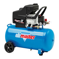
| Category:
Air Compressor
| Size: 5 MB
Table of Contents
Table of Contents
3
1 General Information
5
2 Technical Specifications
6
3 Installation
6
Positioning of the Air Handling Unit
6
Ceiling Brackets
7
Installation of Wall Frames and the Drilling of Duct Holes
8
Installation of the Cooling Module CC 500 or 800
10
Installation of the Air Handling Unit am 500 and 800 to the Wall Frame or Cooling Module
11
Installation with Ceiling Frame
12
Installation of the Air Handling Unit am 150, am 150 with CC 150 (Cooling Module) and am 300
13
Assembling the am 150 and CC 150 before Installation
13
Installation of the Air Handling Unit
13
Installation with Ceiling Frame
14
Installation of the Service Cover
14
Ducts and Grilles
15
Roof Cap
15
Sealing the Gaps Around Ducts
15
Jointing against the Ceiling
16
Fitting of Panels
16
Installation Check
16
Appendix 1 Dimensional Drawings
17
AM 150, am 150 - CC (with Cooling Module) and am 300
17
AM 500 and 800 H
18
AM 500 and 800 V
19
AM 500 and 800 DIDE
20
AM 500 and 800 H - CF (Ceiling Frame)
21
AM 500 and 800 V - CF (Ceiling Frame)
22
AM 500 and 800 H - CC (with Cooling Module)
23
AM 500 and 800 HDIDE - CC (with Cooling Module)
24
Isometric View
25
Model Versions am 500 and 800
29
Appendix 2 Additional Dimensions
30
Connections am 500
30
Connections am 500 - CC
31
Connections am 800
31
Connections am 800 - CC
31
Connections am 800 DIDE
32
Connections am 800 DIDE - CC
33
Ceiling Bracket, Angle
33
Ceiling Bracket, Adjustable
33
Postioning of the Ceilling Brackets
34
AM 500 and 800
34
AM 500 and 800 with Cooling Module (CC)
34
Postioning of the Ceilling Frame
35
AM 500 and 800
35
Advertisement
Related Products
airmaster AMC 150
airmaster AM 50
airmaster AM 100
airmaster AM 1000
airmaster AM 1200
airmaster AM 500
airmaster AM 800
airmaster AM 900
airmaster AME 900 F
airmaster AMX 4
airmaster Categories
Air Compressor
Fan
Air Conditioner
Air Handlers
Vacuum Cleaner
More airmaster Manuals
Login
Sign In
OR
Sign in with Facebook
Sign in with Google
Upload manual
Upload from disk
Upload from URL