Sign In
Upload
Manuals
Brands
ADTRAN Manuals
Network Card
TSU 600
ADTRAN TSU 600 Manuals
Manuals and User Guides for ADTRAN TSU 600. We have
4
ADTRAN TSU 600 manuals available for free PDF download: User Manual, Product Specifications
ADTRAN TSU 600 User Manual (133 pages)
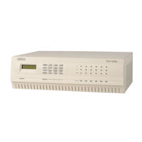
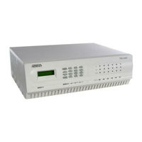
ADTRAN, Inc. USER MANUAL network device TSU 600
Brand:
ADTRAN
| Category:
Network Card
| Size: 1 MB
Table of Contents
Table of Contents
5
Chapter 1. Introduction
13
T1/FT1 Overview
13
T1 Service Offerings
13
Fractional T1
14
TSU 600 Overview
15
Functional Description
15
Figure 1-1. Front View of the TSU 600
15
Tsu 100
15
Tsu 600
15
Identification of Rear Panel Layout
17
Figure 1-2. TSU 600 Rear Panel
17
Features of the TSU 600
18
TSU Interfaces
19
Network Interface
19
Figure 1-3 TSU 600 Interfaces
19
Control Port Input
20
Chain Port Output
20
Three Methods of Control
21
Front Panel
21
ADTRAN PC Program
21
Snmp
21
Option Slot Arrangement
22
Slot 1
22
Slot 2
22
Slots 3-5
22
Slot 6
23
Figure 1-4. TSU 600 Option Slot Arrangement
23
Option Ports
24
Secondary Interfaces (SI)
24
Other Data Interfaces
24
TSU 600 Clock Sources
25
Network Timed
25
Figure 1-5. Network Timed Clock Source
25
DTE Timed
26
Figure 1-6 DTE Clock Source
26
Internal Timing
27
Figure 1-7 Internal Clock Source
27
Normal (CSU) Timing
28
Figure 1-8 Normal (CSU)
28
TSU 600 Testing
29
Self Tests
29
Loopback Tests
29
Classes of Loopbacks
30
DTE Interface Loopbacks
30
Figure 1-9 Network Loopback Tests
30
Network Interface Loopbacks
30
Figure 1-10. DTE Interface Loopback
31
Figure 1-11. Port Interface Loopback
31
Pattern Generation
32
511 Pattern
32
QRSS Generation
32
TSU 600 Configuration Applications
33
TSU 600 Option Modules
33
Bridge, PBX, Video Conferencing Application
33
Figure 1-12. TSU 600 Option Modules
33
Figure 1-13. Bridge, PBX, Video Conferencing Application Set up
33
All Voice Application
34
Figure 1-14. All Voice Application Set up
34
Drop and Insert, and Bridging Application
35
Variations of Mixed Applications
35
Branch Office
35
Regional Sales Office
35
Corporate
36
T-Watch Management Software
36
Chapter 2. Installation
37
Unpack, Inspect, Power Connection
37
Shipped by ADTRAN
37
Provided by Customer
37
Power Connection
38
DC Powered Units
38
Warranty and Customer Service
39
Grounding Instructions (UL 1459)
40
Wiring
42
Network
42
Connections
42
Table 2-A Network Pinout
42
Control In/Chain-In
43
Connections
43
Table 2-B. Control In/Chain-In Pinout
43
Chain-Out
44
Connections
44
Table 2-C Chain-Out Pinout
44
Power up Testing and Initialization
45
Self Test
45
Set User Passcode
46
Special Feature
46
To Establish a Passcode
46
No Passcode Desired
47
Set Unit Identification
47
No Unit ID Desired
47
To Set the Unit Identification
47
Set Control Port
48
Chain-In
48
Control-In (PC)
48
Figure 2-1. Example of Chain-In
49
Normal Power-Up Procedure
50
Correct Passcode
50
Incorrect Passcode
50
No Passcode
50
Chapter 3 . Operation
51
Identification of Front Panel Layout
51
Display Panels
52
Module Status
52
Remote
52
Operation Keys
53
Copy
53
CSU Status
53
Home
53
LCD Window
53
Remote
53
Alarm
54
Cancel
54
Clear
54
Enter
54
Keypad
54
Shift
54
Up and down Arrows
54
Select and Activate a Menu Item
55
General Menu Operation
55
Figure 3-2. Select a Menu Item
55
Figure 3-3. Sample Submenu
56
Set the Data Field
56
Exit any Menu Field Operation or Display
57
Data Port Identification
57
Display Only Data Fields
57
Figure 3-4. Display and Data Fields
57
Menu Structure
59
Figure 3-6. the Four Opening Menus
59
Network Interface (NI) Errors
60
Network Interface Performance Reports (ni PERF RPTS)
60
Opening Menu Functions
60
Active Alarms
60
Figure 3-7. Display of Opening Menus
60
Configuration (CONFIG)
61
DSO Map: a(B)
61
Map Exchange (Map XCHANG)
61
Map in Use
61
Network (NI)
61
Port Configuration(Port Config)
61
Port Status
61
Remote Port
61
Unit
61
View History
61
Factory Restore
62
Set Passcode
62
Software Revision (Software REV)
62
Time/Date
62
Unit ID
62
Utility (UTIL)
62
Cancel Tests
63
Network Tests
63
Port Test
63
Run Self Test
63
Test
63
Status
60
Opening Menu Functions: Detailed Discussion
63
Status
64
Network Performance Reports (ni PERF RPTS)
65
Network Interface Errors (ni ERRORS)
66
Active Alarms
67
Figure 3-10. Network Interface Error Type
67
View History
68
Port Status
68
Remote Port
69
Configuration (CONFIG)
70
Figure 3-12. Complete Configuration Menu
70
Network (NI)
71
Network (NI) Menu Items
71
Operation
71
Unit
73
Operation
73
Unit Menu Items
73
Map Exchange (Map Xchng)
74
Map Exchange (Map Xchng) Menu Items
74
Operation
74
DS0 Map a and DS0 Map B
76
DS0 Map a and Map B Menu Items
77
Operation
77
Figure 3-17. Selected Port and Quantity of Ds0S
79
Map in Use: a(B)
76
Operation
76
Port Configuration (PORT CONFIG)
81
Operation
81
Figure 3-18. Port Configuration
81
Utility (UTIL)
82
Time/Date
83
Operation
83
Summary for Editing Time/Date
83
Factory Restore
84
Operation
84
Set Passcode
85
Change/Set a Passcode
85
Enter Passcode from Other Menus
85
Unit ID: ID
86
Operation
86
Software Revision (Software Rev)
87
Operation
87
Port Utility
88
Operation
88
Test
89
Network Tests
90
Local Loopback
90
Network Tests Menu Items
90
Operation
90
Remote Loopback
91
Pattern
92
Pattern Result
92
Run Selftest
94
Operation
94
Port Tests
95
Operation
95
Cancel Tests
95
Chapter 4. Example Operations
97
Voice and Data MIX
97
Figure 4-1. Example of Voice and Data MIX
97
Steps to Set up Voice and Data MIX
98
Prior to Step 1
98
Step 1. Configure the Network
98
Step 2. Configure DTE Port (1.1 - Nx56/64) (from Option Module)87
99
Step 3. Select the Number of Ds0S/Port
99
Step 4. Complete the DS0 Map Configuration
100
Step 5. Complete a Configuration Table for the DSX-1
101
PBX Passthru
101
Step 6. Activate Configuration Menu
101
Configuring the Network Interface
102
Figure 4-3. First Two Network (NI) Configuration Menu Items
102
Figure 4-4. First Two Network (NI) Menu Items
103
Configuring the DS0 Map
104
Figure 4-5. DS0 Map a and Map B Configuration Menu Items
104
Figure 4-6. Create Map Menu with Displayed DS0 Number
104
Temporary Map
107
Review
107
Figure 4-9. First Screen for Choosing to Review Temporary Files
107
Figure 4-10. a Review Screen
107
Edit
108
Figure 4-12. Window Showing the Error
109
Configuring the Ports
110
Figure 4-13. Window Showing Port Configuration Option
110
Figure 4-14. Screen Used to Change Mode
110
Testing Example
112
Far End Looped Back Test
112
Network Interface Test
112
Figure 4-15. Test Menu One
113
Figure 4-17. Screen that Appears During Loopback Verification
115
Figure 4-19. Test Pattern Results Display
116
Test Termination
117
Appendix A. TSU 600 Menu Tree
119
Appendix B. DTE Data Rate Chart
121
Table B-ADTE Data Rate Vs. Ds0S
122
Appendix C. System Configuration Chart
123
Step 1: Configure Network
123
Step 2: Configure DTE PORT: (1.1Nx56/64)
123
Table C-A. Control Pin Connection Configuration Chart for Network Interface
123
Step 3: Select Number of Ds0S/Port
124
Table C-B. Configuration Chart for DTE Port
124
Step 4: DS0 Map a Configuration
125
Step 5: DS0 Map B Configuration
125
Table C-C. DS0 Map a Configuration
125
Table C-D. DS0 Map B Configuration
125
TSU 600 User Manual 61200.076L2-1
126
Product Support Information
133
Advertisement
ADTRAN TSU 600 User Manual (123 pages)
AADTRAN, Inc.DTRAN, Inc. User Manual cordless telephone 1202076L1, 1202076L1#DC, 1202076L2, 1202076L2#DC
Brand:
ADTRAN
| Category:
Multiplexer
| Size: 2 MB
Table of Contents
Year 2000 Compliance
3
Important Safety Instructions
11
Warranty and Customer Service
12
Table of Contents
13
List of Figures
17
List of Tables
19
Chapter 1 Introduction
21
TSU 600 Overview
21
Product Description
21
Standard Features in the TSU 600
22
TSU Option Modules
23
Figure 1-1. Tsu 600 Option Modules
24
Option Module Architecture
24
TSU 600 Configuration Applications
25
Router, PBX, Video Conferencing Application
25
Drop and Insert, Voice, and Router Application
26
Chapter 2 Installation
27
Unpack, Inspect, Power up
27
Receipt Inspection
27
ADTRAN Shipments Include
27
Customer Provides
27
Power Connection
28
Backup Power Supply (600E Only)
28
DC Powered Units
28
Installing and Replacing the Power Supply
29
Grounding Instructions
30
Identification of Rear Panel Layout
31
TSU 600 Interfaces
35
Chain Port Output
35
Control Port Input
35
Network Interface
35
Network Test Interface
35
10Baset Interface (600E Only)
36
Figure 2-3. Tsu 600 Slot Designation (Rear View)
36
Option Slot Arrangement
36
Power-Up Testing
37
Self-Test
37
Board Level Tests
38
Unit Level Tests
38
Initialization
38
Set Unit Identification
38
Set User Passcode
38
TSU 600 User Manual
38
Chain In/Chain out
39
Chain-In (PC)
39
Set Control Port
39
Normal Power-Up Procedure
40
Chapter 3 Operation
41
Front Panel
41
CSU Status Leds
42
Module Status Leds
43
Operation Keys
45
General Menu Operation
45
Selecting and Activating a Menu Item
46
Editing the Data Field
47
Display Only Data Fields
48
Exit any Menu Field Operation or Display
48
Data Port Identification
49
Front Panel Menu Structure
50
Config (Configuration)
50
Util (Utilities)
50
Alternate Methods of Control
51
T-Watch PRO (ADTRAN PC Program)
51
T-Watch PRO/LAN Connection
51
Snmp
52
T-Watch PRO/EIA-232 Connection
52
Telnet Connection
53
Terminal Mode Connection
53
Chapter 4 Status Menu
55
Figure 4-2. Network Interface Performance Report
56
Network Performance Reports (ni PERF RPTS)
56
Network Interface Errors (ni ERRORS)
57
Active Alarms
58
Figure 4-3. Display of Alarm Messages
58
View History
58
Clear Port Alarm
59
Port Status
59
Remote Port
59
ENET Status (600E Only)
60
PS Status (600E Only)
60
Chapter 5 Configuration Menu
61
Network (NI)
62
Network (NI) Menu Items
62
Figure 5-2. Network Timed Clock Source
64
TSU 600 Clock Sources
64
Network Timing
64
DTE Timing
65
U-BR1TE (Slot 1)
65
Figure 5-4. Internal Clock Source
66
Internal Timing
66
TSU 600 User Manual
66
Secondary Timing
67
Normal (CSU) Timing
68
Unit Menu
69
Map Exchange (Map Xchng) Menu
71
MAP in Use: a(B) Menu
71
DS0 Map a and DS0 Map B Menu
72
Create Temp Example
73
Figure 5-8. Create Temp Selection Screen
74
Port Configuration (Port Config)
75
Figure 6-1. Utility Menu Tree
77
Chapter 6 Utility Menu
77
Time/Date
78
Factory Restore
78
Set Passcode
78
Enter Passcode from Other Menus
78
Change/Set a Passcode
79
Automatic Time-Out Feature
79
No Passcode Desired
79
Unit ID
79
Setting the Unit Identification
80
No Unit ID Desired
80
Software Revision (Software Rev)
80
Port Utility
80
ENET Address (600E Only)
80
CMD Mode
80
Chapter 7 Test Menu
81
Network Tests
82
Loopback Tests
82
Figure 7-2. Network Loopback Tests
83
Network Interface Loopbacks
83
Local Loopbck
83
Remote Loopbk
84
Test Pattern
85
QRSS Pattern
85
Pattern Result
86
Run Self-Test
87
Board Level Tests
87
Unit Level Tests
87
Port Tests
88
Cancel Tests
88
Figure 8-1. Telnet/Terminal Main Menu
89
Chapter 8 Telnet/Terminal Menus
89
Main Menu
89
Status, Config, Util, and Test Menu Options
90
DS0 Maps Configuration Menu
90
Initializing the Temp Map
91
Applying the Temp Map
92
Editing the Temp Map
92
Reviewing Maps
92
Remote Menu Access
93
Management Configuration
93
Unit Access Table
93
Add New Unit
94
Delete Unit
94
Modify Unit
94
Default Unit Passcode
95
SNMP Read Community
95
SNMP Read/Write Community
95
SNMP Trap Community
96
System Contact
96
System Location
96
System Name
96
Auto. Fail Traps Sent
97
Exit
97
Ping IP Host
97
Poll Link Status Traps Sent
97
Telnet/Terminal Password
97
Telnet/Terminal Time-Out
97
Flash Download
97
Quit Session
97
Basic Components
99
Network Manager
99
Appendix A Understanding SNMP
99
Index
100
Snmp Trap Configuration
101
Tsu 600 Snmp Access
101
Snmp Mib Browser Configuration
102
Snmp Mib Files
102
Appendix B Understanding
103
Tr-08 Ds0 Conversion Table
105
Network Connections
107
Appendix C Network Pinouts
107
Control In/Chain in
108
10Baset Connections
110
Appendix D System Messages
111
Electrical Specifications
113
Appendix E Specifications
113
Management Interfaces
114
Environmental Specifications
115
Index
117
Product Support Information
123
ADTRAN TSU 600 User Manual (78 pages)
Data/Channel Service Unit
Brand:
ADTRAN
| Category:
Network Hardware
| Size: 0 MB
Table of Contents
User Manual
1
Federal Communications Commission Radio Frequency Interference Statement
5
Important Safety Instructions
6
Save These Instructions
6
Warranty and Customer Service
7
Table of Contents
9
Chapter 1. Introduction
17
T1/FT1 Overview
17
T1 Service Offerings
17
Fractional T1
18
TSU Overview
19
Functional Description
19
Figure 1-2. Tsu Rear Panel
20
Features
21
Interfaces
21
Network Interface
22
Chain Port Output
22
Control Port Input
22
Nx56/64 Serial Interface
22
Three Methods of Control
23
Adtran PC Program
23
Front Panel
23
Snmp
23
TSU Clock Sources
24
Network Timed
24
DTE Timed
25
Figure 1-5. Dte Clock Source
25
Figure 1-6. Internal Clock Source
26
Internal Timing
26
TSU Testing
27
Loopback Tests
27
Self Tests
27
Network Loopbacks
28
All Ones
29
DTE Interface Loopbacks
29
Pattern Generation
29
Application
30
Chapter 2. Installation
31
Unpack, Inspect, Power Connection
31
ADTRAN Shipments Include
31
Customer Provides
31
Power Connection
31
Wiring
32
Network
32
Control In/Chain in
33
Chain out
34
Nx56K/64K DTE (V.35)
35
Power up Testing and Initialization
36
Self Test
36
Chapter 3. Operation
37
Methods of Operation
37
Front Panel Operation
38
Lcd Window
38
General Menu Operation
39
Arrows
39
Data Field
39
Display Field
39
Example Menu Operation
39
Setting the Data Field
40
To Exit any Menu Field Operation or Display
41
Viewing Display Only Data Fields
41
Menu Structure
42
The Four Opening Menu Functions
43
Config
43
Curr Err/Alm
43
Err/Alm Hist
43
Network (Ni)
43
Ni Perf Rpts
43
Port
43
Status
43
Unit
43
Address
44
Fact Restore
44
Network Tests
44
Reinit Unit
44
Run Self Test
44
Software Version
44
Test
44
Time/Date
44
Util
44
Menu Operation
45
Status Menu
45
NI PERF RPTS, Submenu of 1)Status
46
CURR ERR/ALM Submenu of 1)Status
48
Clear History
49
ERR/ALM Hist Submenu of 1)Status
49
Configuration
50
Network (Ni) Submenu of 2) Config
51
Bit Stuffing
52
Clock Source
52
Cntrl Port
53
Modem Init
53
Unit, Submenu of 2) Config
53
Alarms
54
Port, Submenu of Config
55
Util
57
Time/Date, Submenu of 3)Util
57
Reinit Unit, Submenu of 3)Util
59
Software Rev, Submenu of 3)Util
59
Address,Submenu of 3)Util
60
Fact Restore, Submenu of 3)Util
60
Test
61
Figure 3-6. Complete Test Menu
61
Network Tests, Submenu of 4)Test
62
Run Selftest, Submenu of 4)Test
64
Port Tests Submenu of 4)Test
65
Run Selftest
65
Chapter 4. Testing Example
67
Far End Looped Back Test
67
Network Interface Test
67
Cancel Key
69
Test Pattern
69
Index
75
Product Support Information
77
Advertisement
ADTRAN TSU 600 Product Specifications (2 pages)
Preconfigured Plug-and-Play T1/FT1 Multiplexers for Voice or Data
Brand:
ADTRAN
| Category:
Multiplexer
| Size: 0 MB
Advertisement
Related Products
ADTRAN TSU ACE
ADTRAN 239 T1 HDSL4
ADTRAN TRACER 6000 SERIES
ADTRAN TRACER Protection Switch
ADTRAN TSU 600e
ADTRAN TSU 610
ADTRAN TSU 610 HDSL
ADTRAN TSU 120e
ADTRAN TSU 100
ADTRAN TSU FT1
ADTRAN Categories
Network Hardware
Network Router
Switch
Gateway
Control Unit
More ADTRAN Manuals
Login
Sign In
OR
Sign in with Facebook
Sign in with Google
Upload manual
Upload from disk
Upload from URL